Page is loading ...

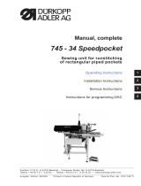
Manual, complete
745 - 34 - 1, -3
Sewing Unit for Runstitching of Piped Flap
and Welt Pocket Openings and Pocket Cor ners
WorkingMethods:A,B,D,F
Operating Instructions
Installation Instructions
Service Instructions
Instructions for Programming DAC
Postfach 17 03 51, D-33703 Bielefeld • Potsdamer Straße 190, D -33719 Bielefeld
Telefon + 49 (0) 5 21 / 9 25-00 • Telefax + 49 (0) 5 21 / 9 25 24 35 • www.due rkopp-adler.c om
1
2
3
4
Ausgabe / Edition: Änderungsindex Teile-Nr./Part.-No.:
11/2011 Rev. index: 03.0 Printed in Federal Republic of Germany 0791 745181

745 - 34 - 1, -3
Manual, complete
Content
Operating Instructions
Installation Instructions
Service Instructions
Instructions for Programming DAC
Interconnection Diagram
9870 745154 B
9890 745002 B
Pneumatic Circuit Plan
9770 745005
All rights reser ved.
Property of Dürkopp Adler AG and copyrighted. Reproduction or publication of the content
in any manner, even in extracts, without prior written permission of Dürkopp Adler AG, is
prohibited.
Copyright ©
Dürkopp Adler AG - 2011

Foreword
This instruction manual is intended to help the user to become familiar
with the machine and take advantage of its application possibilities in
accordance with the recommendations.
The instruction manual contains important information on how to
operate the machine securely, properly and economically. Observation
of the instructions eliminates danger, reduces costs for repair and
down-times, and increases the reliability and life of the machine.
The instruction manual is intended to complement existing national
accident prevention and environment protection regulations.
The instruction manual must always be available at the machine/sewing
unit.
The instruction manual must be read and applied by any person that is
authorized to work on the machine/sewing unit. This means:
– Operation, including equipping, troubleshooting during the work
cycle, removing of fabric waste,
– Service (maintenance, inspection, repair) and/or
– Transport.
The user also has to assure that only authorized personnel work on the
machine.
The user is obliged to check the machine at least once per shift for
apparent damages and to immediatly report any changes (including the
performance in service), which impair the safety.
The user company must ensure that the machine is only operated in
perfect working order.
Never remove or disable any safety devices.
If safety devices need to be removed for equipping, repairing or
maintaining, the safety devices must be remounted directly after
completion of the maintenance and repair work.
Unauthorized modification of the machine rules out liability of the
manufacturer for damage resulting from this.
Observe all safety and danger recommendations on the machine/unit!
The yellow-and-black striped surfaces designate permanend danger
areas, eg danger of squashing, cutting, shearing or collision.
Besides the recommendations in this instruction manual also observe
the general safety and accident prevention regulations!

General safety instructions
The non-observance of the following safety instructions can cause
bodily injuries or damages to the machine.
1. The machine must only be commissioned in full knowledge of the
instruction book and operated by persons with appropriate training.
2. Before putting into service also read the safety rules and
instructions of the motor supplier.
3. The machine must be used only for the purpose intended. Use of
the machine without the safety devices is not permitted. Observe all
the relevant safety regulations.
4. When gauge parts are exchanged (e.g. needle, presser foot, needle
plate, feed dog and bobbin) when threading, when the workplace is
left, and during service work, the machine must be disconnected
from the mains by switching off the master switch or disconnecting
the mains plug.
5. Daily servicing work must be carried out only by appropriately
trained persons.
6. Repairs, conversion and special maintenance work must only be
carried out by technicians or persons with appropriate training.
7. For service or repair work on pneumatic systems, disconnect the
machine from the compressed air supply system (max. 7-10 bar).
Before disconnecting, reduce the pressure of the maintenance unit.
Exceptions to this are only adjustments and functions checks made
by appropriately trained technicians.
8. Work on the electrical equipment must be carried out only by
electricians or appropriately trained persons.
9. Work on parts and systems under electric current is not permitted,
except as specified in regulations DIN VDE 0105.
10. Conversion or changes to the machine must be authorized by us
and made only in adherence to all safety regulations.
11. For repairs, only replacement parts approved by us must be used.
12. Commissioning of the sewing head is prohibited until such time as
the entire sewing unit is found to comply with EC directives.
13. The line cord should be equipped with a country-specific mains
plug. This work must be carried out by appropriately trained
technicians (see paragraph 8).
It is absolutely necessary to respect the safety
instructions marked by these signs.
Danger of bodily injuries !
Please note also the general safety instructions.

Contents page:
Part 4: Instructions for Programming DACIII, class 745-34-1 and 745-34-3
Program version A 01
1 General ................................................... 3
2 Operating terminal ............................................ 4
3 Selecting the language ......................................... 5
4 Memory dongle .............................................. 6
4.1 Transferring data from the memory dongle to the control ..................... 6
4.2 Transferring data from the c ontrol to the memory dongle ..................... 6
5 Main operating screen ......................................... 8
5.1 Sewingandtestprograms:menustructure.............................. 8
5.2 Changingparametervalues....................................... 9
6 Sewing programs ............................................. 10
6.1 Calling sewing-program parameter screens ............................. 10
6.2 Running a machine program ....................................... 11
6.3 Mainscreen................................................. 12
6.4 Pocket programs ............................................. 14
6.5 Blowermode................................................ 34
6.6 Pocket sequence ............................................. 36
7 Setting and test programs ....................................... 38
7.1 Calling setting and test programs ................................... 38
7.2 Machineparameters ........................................... 40
7.3 Machine-specificsettingandtestprograms............................. 48
7.3.1 Adjustingthelooper-threadmonitor.................................. 49
7.3.2 Initializingmemory ............................................ 50
7.3.3 Checking the smoother function .................................... 51
7.3.4 Aligningthelightbarriers ........................................ 52
7.3.4.1 Preparingthesewingunitandfeedclamps.............................. 53
7.3.4.2 Sewing unit with two light barriers for automatic angle recognition ............... 55
7.3.4.3 Sewingunitwithtwolightbarriers,leftorrightflappositioning................. 57
7.3.4.4 Sewingunitwithonelightbarrier.................................... 59
7.3.4.5 ErrorDisplay................................................ 60
7.3.5 Checking the corner-blade settings .................................. 61
7.3.5.1 Checking the cor ner-blade station ................................... 62
7.3.5.2 Checking the front left corner blade .................................. 62
7.3.5.3 Checking the rear left corner blade .................................. 62
7.3.5.4 Checking corner-blade motion ..................................... 63
7.3.5.5 Corner-blademachineparameters................................... 64
4

Contents page:
7.3.6 Testingneedleandcenter-bladeactivation.............................. 66
7.3.7 Checking the tape feed.......................................... 67
7.3.8 Checking the gripper folder without feed clamp (versions B and F only) ............ 68
7.3.9 Checking the insertion process with feed clamp .......................... 69
7.3.10 Checking and adjusting the piping knives .............................. 70
7.3.10.1 C hecking the piping knife motion .................................... 70
7.3.10.2 Settingthepipingknifereferenceposition.............................. 71
7.3.11 Step-by-stepmode............................................ 72
7.3.12 Determiningthecycletime ....................................... 73
7.3.13 Dongle Menu ................................................ 74
7.3.14 Testingtheincrementalencoder.................................... 75
7.4 Multitest system .............................................. 76
7.4.1 Displaying the program version and checksum ........................... 77
7.4.2 TestingRAM ................................................ 78
7.4.3 Selectinginputelements......................................... 79
7.4.4 Checking input elements......................................... 81
7.4.5 Selectingoutputelements........................................ 82
7.4.6 CANtest................................................... 85
7.4.7 Checking the sewing drive ........................................ 86
7.4.8 Errorlist................................................... 87
7.5 Terminalself-test ............................................. 88
7.6 Displaycontrastvalue .......................................... 89
7.7 Editingmenus ............................................... 90
7.8 Adjustingtheserialinterface ...................................... 91
8 Error messages .............................................. 92
8.1 Sewingmotorcontrollererrormessages............................... 92
8.2 Steppingmotorerrormessages .................................... 93
8.3 Operatingindicatorerrormessages.................................. 93

4
1 General
This manual contains important information on the safe a nd correct
use of the “DACIII” (Dürkopp Adler Control) new-generation controller.
Screen images in this brief description
The symbol display on the various screens depends on the sewing
machine’s equipment and settings. The screen images illustrated in
this brief description may therefore not always correspond exactly
with the screens appearing in the controller display.
Operating terminal with graphic user guide
The operating terminal is fitted with an LCD display and a keyboard.
The user guide employs only inter nationally intelligible symbols,
supplemented with textual information in the selected language. The
various symbols are arranged in groups in the menu structure of the
sewing and test programs.
Simplicity of operation ensures rapid familiarization.
Ease of programming
99 freely programmable pocket programs are available t o the user,
which can be combined with any number of seam patterns.
20 pocket sequences.
Each pocket sequence can be composed of a maximum of 8
pocket programs in any order.
On the “slanting-pocket version” of the class 745-34-3 all practical
angles can be programmed by the operator,
who can thus dispense with the need to spend time and effort
readjusting the cor ner blades and programming seam displacements.
Setting and test programs
The MULTITEST comprehensive testing and monitoring system is
integral to the DACIII control.
A microcomputer carries out the control functions, monitors the
sewing process and displays incorrect operations and faults.
Errors and test results are shown in the LCD display.
If the machine is operating normally the display shows information
relating to operation and sewing.
In the event of an operating error or fault t he function sequence is
interrupted. The display indicates the cause by means of the
appropriate error symbol.
In most cases the error symbol disappears once the error has been
rectified.
In some cases the main switch must be switched off for safety
reasons when the error is rectified.
Special programs facilitate mechanical settings and enable receiver
and transmitter elements to be rapidly tested without additional
measuring devices.
Memory dongle
The dongle is used to memorize sewing programs and machine
parameters and to transfer these data to other sewing units.
3

2 Operating terminal
Data input and output is done via an operating terminal with a colour
LCD display and a multipurpose keyboard.
RST (reset)
key
Colour display
Decimal
keypad
Cursor keys
OK key
ESC key Function keys
Key/key group Function
Function keys Call sewing-program parameter screens
(from the main screen).
Call test programs (after pressing the RST key)
Switch functions on and off.
Leave test programs and parameter screens.
Cursor keys Change parameter values.
Change parameter values.
ï, ð : select the symbol of the required parameter
ñ, ò : switch the parameter function on and off,
select the previous/next parameter-value stage,
activate the test program
Decimal keypad Enter parameter values.
: change the parameter-value sign
Escape key Display the old parameter value again.
OK key Open window to set the selected parameter.
Accept the set parameter value.
RST key Leave machine program.
Halt current program.
4

3 Selecting the language
–
Switch on the main switch and keep pressing the “ñ” k ey or
–
Press the keys “RST” and “ñ” in order to activate the language
selection
–
The different languages are memorized in the control.
–
By pressing the cursor keys “ñ“or”ò” the desired language can
be selected (it will appear white on black).
–
With the “F5” k ey the language that will be activated when
switching on the automat the next time is marked with an asterisk.
4
5

4 Memory dongle
The dongle is used to memorize sewing programs and machine
parameters and to transfer these data to other sewing units.
The transfer direction is selected with the keys ”F2”and“F4”. The
data transfer is started with the “F5” key.
4.1 Transferring data from the memory dongle to the control
–
Use the “ð ”or“ï” cursor keys, to select the required parameter
(machine parameter, sequences or seam program).
–
The pictogram representing the required parameter will then
appear white on black.
–
Start the data transfer by pressing the “F5” key.
F1 F2 F3 F4 F5
4.2 Transferring data from the control to the memory dongle
–
When saving data on the dongle, all parameters, machine
parameters, sequences and seam programs are memorized.
–
After pressing the “F5” key, appears the question whether the
dongle is to be overwritten.
F1 F2 F3 F4 F5
–
The current type of the dongle being plugged in is determined and
indicated on the display.
–
Data transfer can be started by pressing the “F5” key and stopped
with the “ESC”key.
–
If no data dongle 745-34-3 is indicated but e. g. Boot 745-34-3, the
dongle will first be formatted after pressing the “F5” key before the
data are saved on the dongle.
6

4
–
The dongle is formatted
–
The data is saved onto the dongle
7

5 Main operating screen
5.1 Sewing and test programs: menu structure
The user interface exclusively employs inter nationally intelligible
symbols.
In addition each function is briefly explained in an information line.
The individual parameters and setting and t est programs are arranged
in various groups.
Turn on
main switch
Main screen
Sewing programs Setting and test programs
Calling sewing programs
–
Tur n on the main switch.
The controller is initialized.
The DÜRKOPP-ADLER logo briefly appears in the display.
–
The display switches to the main screen.
Sewing-program parameter menus are called by pressing one of
the function keys F1 and F2.
Calling setting and test programs
–
Tur n on the main switch.
The controller is initialized.
The DÜRKOPP-ADLER logo briefly appears in the display.
–
While the logo is displayed press one of the function keys F1 to
F5 or cursor up, cursor down.
or with the machine switched on:
–
press the RST key, then hold down one of the function keys F1 to
F5 or cursor up, cursor down.
The display switches to the corresponding group of setting or test
programs.
8

5.2 Changing parameter values
Parameter values are changed in the individual parameter screens.
–
Select the required parameter with the “ï”or“ð” cursor keys.
A black background appears behind the symbol of the selected
parameter.
–
Press the OK key.
The settings window appears with the current v alues or to enable
values to be entered.
–
Change the parameters as described under 1 to 4 below.
–
Press the OK key.
The new parameter settings are saved.
When changing parameter values we must distinguish among four
groups of parameters:
1. Functions that are switched on and off
–
Switch the parameter function on and off with the “ð”or“ï”
cursor keys.
(on) (off)
2. Parameters with various functions
–
Set the required parameter function with the “ð”or“ï”cursor
keys.
3. Parameters whose values are changed in stages
–
Select the previous or next parameter-value stage with the “ñ ”or
“ò” cursor keys.
Entry:
10, 12, 14, 16, 18, 20, 22, 24, 26, 30
4. Parameters whose values are entered with the decimal keypad
–
Enter the required parameter value on the decimal keypad.
CAUTION:
The value must be within the set limits.
If the value entered is too large or too small, the upper or lower
limit is displayed when the Enter key is pressed.
[-20 ...+20]
–
If a plus or minus sign appears in front of the parameter value, it
can be changed with the “ ” key.
4
9
20

6 Sewing programs
With Class 745-34-3 you can program up to 99 different sewing
programs.
The individual sewing programs (pocket programs) are freely
programmable.
20 independent pocket sequences are available. Each pocket
sequence can be composed of a maximum of 8 pocket programs in
any order.
6.1 Calling sewing-program parameter screens
You can switch from the main screen to the various sewing-program
parameter screens with function keys F1 and F2. Function key F5
resets the piece counter to “0". Press F4 for the tape feed (if present).
Piece counter
Pocket Program Sequence
PP Seq
Parameters and sewing-program parameter screens
Pocket Program (PP) : parameters for programming the
seam and the
associated additional functions.
Sequence (Seq) : programming pocket sequences
Piece counter : daily piece counter
10

6.2 Running a machine program
–
Tur n on the main switch.
The controller is initialized.
–
The Dürkopp Adler Logo briefly appears in the display.
–
The controller checks the position of the transport carriage.
The following display appears:
Info line:
Reference run
–
Start the reference run by pushing the left pedal back.
–
The display switches to the main screen of the sewing unit.
You can switch from the main screen to the various parameter
screens with function keys F1 or F2.
–
Press the RST key to leave the machine program.
The controller is re-initialized.
4
11

6.3 Main screen
The main screen displays the seam pattern, sewing program, selected
pocket sequence and important parameters.
Parameters can be individually selected by the user.
Info line
Seam patter n
The left half of the display shows the seam pattern of the selected
pocket program.
Sequence
A box indicating the sequence appears in the top right-hand cor ner.
Selecting program number and pocket sequence
The selected pocket sequence is displayed in the top right-hand
corner.
If automatic pocket-program switching is on, arrows are displayed
between the individual pocket programs of the sequence.
–
Select a pocket sequence with cursor keys “ñ”or“ò”.
“ò” : select next pocket sequence
“ñ” : select previous pocket sequence.
Selecting a pocket program in the current pocket sequence
In the pocket sequence the selected pocket program is shown in
rev e rs e v id e o.
–
Select a pocket program with cursor keys “ð”or“ï”.
“ð” : select next pocket program
“ï” : select previous pocket program.
12

Parameters
The symbols in the center of the right half of the display give rapid
access to important parameters.
Up to ten parameters can be selected by the operator for display on
the main screen (see also section 6.7).
Parameters can be changed directly on the decimal keypad.
The number of the key to be pressed is displayed to the right of the
parameter symbol.
Example:
0: carriage-return to stand-by position
1: slide-in velocity
2: flap sequence
3: holder
4: vacuum
5: breast welt
6: pocket-program name
7: save pocket program
8: smoother
9: smoother time
The functions and settings of individual parameters are described in
more detail in section 5.4: Pocket programs.
The selection of the parameter symbols is described in section 6.7.
Info line
Text explaining the selected function is displayed in the information
line.
Piece counter
The current piece count is displayed at bottom right
(e.g. ).
The piece counter shows the number of pieces completed since the
counter was last reset.
The piece counter can be reset to “0" by pressing function key F5.
4
13

6.4 Pocket programs ( )
This menu item contains the parameters for programming the various
pocket programs.
They are used to program the seam and its associated additional
functions.
Info line:
Select pocket program
–
While the main screen is displayed press function key F1.
The display switches to the pocket-program screen.
–
The pocket program currently s elected is shown in the upper part
of the display (e.g. “PP : 01”).
The program name, if any, appears behind it (e.g. “<SAKKO>”).
–
Select the required parameter with cursor keys “ï”or“ð”.
A black box appears under the symbol of the selected parameter.
–
Change the selected parameter as described in section 4.2.
–
Press function key F1 to switch back to the main screen.
Pocket-program number
This parameter selects the pocket program that is to be changed.
On completion of the entry the new pocket program and its program
name appear in the top left-hand corner of the display.
Entry: 1 .. 99
14

Programming the seam pattern
The actual pocket form is programmed under this menu item. The
programmed pocket is shown with the corresponding information in
the left half of t he display.
The corresponding parameter symbols appear in the right half.
–
Select the required parameter with cursor keys “ï”, “ð”, “ñ”or
“ò”.
The symbol of the parameter selected appears in reverse video.
–
Press the OK key.
The corresponding submenu is called.
Seam-start flap shape
This parameter is used to select the shape of the flap at the seam
start. Three variants are available:
Straight flap
Slanting flap (left)
Slanting flap (right)
–
Select the required flap shape with cursor keys “ï”or “ð”.
–
Press the “OK ” key.
The flap-angle entry window appears.
Flap angle
Entry: 01 … 13 [mm]
4
15

Seam-start patter n
This parameter selects the form of the seam patter n at the seam start.
Straight seam pattern
Slanting seam pattern (left)
Slanting seam pattern (right)
–
Select the required seam form with cursor keys “ï”or “ð”.
–
Press the “OK ” key.
The seam-angle entry window appears:
Seam angle
Entry: 01 … 13 [mm]
Seam-end flap shape
This parameter selects the form of the flap at the seam end. Three
variants are available:
Straight flap
Slanting flap (left)
Slanting flap (right)
–
Select the required flap shape with cursor keys “ï”or “ð”.
–
Press the “OK ” key.
The flap-angle entry window appears:
Flap angle
Entry: 01 … 13 [mm]
16
/

