Page is loading ...

A50/A51/A60
Feb. 1997 ( 1st Edition )
All Rights Reserved

Part I - A50/A51 RS-232 to RS-422/RS-485 Converter
A50/A51
RS-232 to RS-422/RS-485
Bidirectional Converter

Part II - A60 RS-232 Surge Protection
A60
RS-232 Surge Protection
Converter

Copyright Notice
This documentation is copyrighted by Moxa Technologies Co., Ltd.
All rights are reserved. Moxa Technologies reserves the right to
make improvements to the products described in this manual at any
time without notice.
Information provided in this manual is intended to be accurate and
reliable. However, Moxa Technologies assumes no responsibility for
its use, nor for any infringements of rights of the fourth party which
may result from its use.
MOXA is a registered trademark of Moxa Technologies Co., Ltd.
The other trademarks in this manual belong to their manufacturers
individually.
Moxa Technologies Co., Ltd.
Tel: +866-2-8665-6373
Fax: +886-2-8665-6372
www.moxa.com.tw
support@moxa.com.tw

M
o
x
a
I
n
t
e
r
n
e
t
S
e
r
v
i
c
e
s
Customer’s satisfaction is always our number one concern. To
ensure customers get the full benefit of our services, Moxa Internet
Services (MIS) have been built for technical support, product inquiry,
new driver upgrade, etc.
The followings are the services we provide.
E-mail for technical support
address : su[email protected]
Ftp site for free driver upgrade
address : ftp.moxa.com or ftp.moxa.com.tw
user ID : ftp
password : your_email_address
World Wide Web (WWW) for product info.
address : www.moxa.com or www.moxa.com.tw

Table of Contents
Part I - A50/A51 RS-232 to RS-422/RS-485 Converter
Chapter 1. Introduction ………………………………………. 1
1.1 Overview 1
1.2 Features and Specifications 2
1.3 Package Check List 5
Chapter 2. Installation ……………………………………….. 7
2.1 Installation Procedure 7
2.2 Switch Function Description 7
2.3 LED Indicators 8
2.4 RS-422/RS-485 Pinouts 9
Chapter 3. Operation ………………………………………… 11
3.1 Point-to-point 12
3.2 Multidrop 14
3.3 Simplex/Transmit, Receive 17
3.4 Self Test 19
Appendix A RS-232 Pinouts and Cable Wiring ……………….. 21
Appendix B Impedance Matching and Termination Resistors…… 25
Appendix C Troubleshooting …………………………………. 27

Table of Contents
Part II - A60 RS-232 Surge Protection
Chapter 1. Introduction…………………………………………… 29
1.1 Overview 30
1.2 Features and Specifications 30
1.3 Package Check List 31
Chapter 2. Installation……………………………………………… 33
2.1 Installation Procedure 33
2.2 LED Indicators 34
2.3 Self Test 36
Appendix A RS-232 Pinouts and Cable Wiring…………………… 37
Appendix B Troubleshooting ……………………………………….. 41


1
Chapter1 Introduction
1.1 Overview
The MOXA RS-232 to RS-422/RS-485 bidirectional converters,
A50 and A51, are designed to convert unbalanced (single-ended)
RS-232 signals to balanced (differential) RS-422/RS-485
signals, and vice versa. They are the best choices for those who
want to control devices at longer distance and/or to
communicate with several devices via merely one link,
particularly in the industry area. Point-to-point, multidrop and
simplex operations are available for most users' needs.
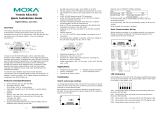
Outlook of A50
RS-422/485
RJ-45 Connector
Power Jack
RS-232
RJ-45 Connector
RS-422/485 RS-232
C
onverter
RS-232toRS-422/485
A50
T
X
D
R
X
D
R
T
S
P
W
R

Introduction Chapter 1
2
Outlook of A51
1.2 Features and Specifications
Features
Both A50 and A51 are RS-232 to RS-422/RS-485 bidirectional
converters except that A51 has one more feature: isolation
protection, which provides high voltage protection up to 2000V.
All the switches, SW1 and SW2, of A50/A51 are designed to be
inside of the converter to protect switch settings from
unintended change and introducing communication error
without any warning. Hence, it is necessary to take the two
screws off and open the cover up if you need to change the
operation mode via sliding the switches.
The A50/A51 must be powered either from a DC +9V to +30V,
RS-422/485
RJ-45 Connector
Power Jack
RS-232
RJ-45 Connector
RS-422/485 RS-232
A51
C
onverter
IsolatedRS-232toRS-422/485
A51
T
X
D
R
X
D
R
T
S
P
W
R

Chapter 1 Introduction
3
150mA power adapter or the pin 6 and pin 7 of the Terminal
Block.
LED indicators are provided to show the status of data
transmitting/receiving, RTS signal and Power.
To avoid over-current from the remote ground to converter's
ground, an protect resistor has been added inside the A50/A51.
Specifications
v Power Supply - DC +9V to +30V, 150mA
v Data Rate - Up to 921600 bps under 500 ft (0.15 Km)
v Distance - Up to 4000 ft (1.2 Km) under 115200 bps
v RS-232 RJ-45 Connector -
Supports TxD, RxD, DTR, DSR, RTS, CTS, DCD, GND
v RS-422/RS-485 RJ-45 Connector -
Supports TxDA, TxDB, RxDA, RxDB, GND
v RS-422/RS-485 Terminal Block Connector -
Supports TxDA, TxDB, RxDA, RxDB, GND, PWR, PWR
GND
v Switch - SW1 : for full/half-duplex mode
SW2 : for Tx (driver) and Rx (receiver) state

Introduction Chapter 1
4
v Isolation Protection - for A51 only, up to 2000V.
v Terminal Resistor - RT1 space reserved for RS-422/RS-485
receiver signal.
v Mounting Kit - Plastic Plates and screws for mounting
A50/A51 on the wall or any surface.
A50/A51 with Mounting Kit
RS-422/485 RS-232
C
onverter
RS-232toRS-422/485
A50
Mounting
Screw
Fixing Screw
T
X
D
R
X
D
R
T
S
P
W
R

Chapter 1 Introduction
5
1.3 Package Check List
Upon unpacking your A50 or A51 package, you should find the
following items:
v A50 (or A51) RS-232 to RS-422/RS-485 bidirectional
converter (with isolation protection if A51)
v One power adapter
v Mounting Kit
v A50/A51/A60 User's Manual

Introduction Chapter 1
6

7
Chapter 2 Installation
2.1 Installation Procedure
As RS-232 or RS-422/RS-485 port are labeled clearly on the
surface of the A50/A51 converter, please prepare the RS-232
cable (refer to Appendix A, RS-232 Cable Wiring) and decide
the operation mode as well as 2/4-wire cable (refer to Chapter 3,
Operation) in advance.
Take off the two screws on top of the converter and open the
cover up if you need to change the operation mode via sliding
the switches.
2.2 Switch Function Description
Inside look of A50/A51
SW1 SW2
ON
1 2 3 4
ON
1

Chapter 2 l l Installation
8
Switch settings table of SW1 and SW2 is as follows:
SW1
*Full-duplex mode Off
Half-duplex mode On
SW2 Pin1 Pin2 Pin3 Pin4
*TxD always enabled On Off X X
TxD always disabled Off Off X X
TxD enabled by RTS Off On X X
*RxD always enabled X X On Off
RxD enabled by /RTS X X Off On
Note: ‘ * ‘ means default settings , ‘ X ‘ means don’t care
2.3 LED Indicators
There are LED indicators for TxD, RxD, RTS, and PWR on top
of A50/A51. The indicator is not lighted on when not connected
with signal or power. On the contrary, it will be lighted on and
be in one of the red, green or orange colors.
TxD indicator stands for data transmitting from RS-232 to
RS-422/RS-485. It shows green when connected and no data
transmitting. It shows orange when connected and transmitting
data.

Installation l l Chapter 2
9
RxD indicator stands for data transmitting from RS-422/RS-485
to RS-232. It shows red when connected and no data received. It
shows orange when connected and receiving data (In half-
duplex mode, it shows red when line is not connected due to the
characteristics of ICs for RS-485).
RTS indicator is for RS-232 RTS signal. It shows red when
connected and RTS signal turned on. It shows green when
connected and RTS signal turned off.
PWR indicator is red when power is on and not lighted when
power is off or not connected.
2.4 RS-422/RS-485 Pinouts
RS-422/RS-485 interface with RJ-45 Jack connector or
Terminal Block Connector is depicted as follows.
1 2 3 4 5 6 7
RJ-45 Connector Terminal Block Connector
1 2 3 4 5 6 7 8 9 10

Chapter 2 l l Installation
10
A50/A51 A50/A51
RJ-45 Jack Terminal Block
Connector Pinouts Signals Connector Pinouts Signals
1 nc 1 TxD B
2 nc 2 TxD A
3 GND 3 RxD B
4 TxD B 4 RxD A
5 TxD A 5 GND
6 RxD A 6 Power GND
7 RxD B 7 Power Input
8 GND
9 nc
10 nc(not connected)
Note : Pin 6 and Pin 7 of Terminal Block are for Power GND
and Power Input, which is an alternate option for power
adapter. Be careful that DO NOT confuse RS-422/RS-
485 GND with Power GND.
Note : Under half-duplex mode (SW1 in ON mode), the
couples of (TxD B, RxD B) and (TxD A, RxD A) are
shorted inside the converter for convenience. Users can
save the trouble with shorting the wires.

~11~
Chapter 3 Operation
The A50 (or A51) supports 5 kinds of operations. They are:
v Point-to-point/4-wire Full Duplex
v Point-to-point/2-wire Half Duplex
v Multidrop/4-wire Full Duplex
v Multidrop/2-wire Half Duplex
v Simplex/Transmit, Receive Only
All the operations are to be described below. And TA, TB, RA
and RB represent TxD A, TxD B, RxD A and RxD B signal
lines of the RJ-45 RS-422/RS-485 connector or the Terminal
Block, respectively.
Note : If possible, connect GND of both sides together to gain
better signals. That is, you may need one more GND
connection in addition to 4-wire or 2-wire connection.
Note : For A51, connecting GND at the Terminal Block to the
earth ground to provide a ground path to prevent
electric shock caused by lightning, no matter RJ-45 or
Terminal Block RS-422/RS-485 is used.

Chapter 3 l l Operation
12
3.1 Point-to-point
Point-to-point configuration means two devices which locate at
two different places can be linked together to communicate
through a couple of A50 (or A51) converters.
4-wire Full Duplex
In the graph, TA, TB, RA and RB could be either from RJ-45 or
Terminal Block. The settings of the switches for each A50 (or
A51) are as follows:
SW1 SW2 Pin1 Pin2 Pin3 Pin4
Full-duplex mode Off TxD always enabled On Off X X
RxD always enabled X X On Off
A50/A51A50/A51
RS-232
RA
RB RS-422/ RS-232
TB RS-485
TA
GND
TA
RS-422/ TB
RS-485 RB
RA
GND
DTE/
DCE
DTE/
DCE
/