
Fire Alarm Systems | FLM‑I 420‑S Short Circuit Isolator
The Short Circuit Isolator isolates alarm zones in which a
short circuit has occurred. This means the functionality of
the remainder of the network remains preserved.
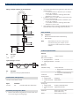
System Overview
b1+ a- b2+ N/A N/A N/A
LSN
9 1
6 4
7 3
8 2
0
5
8 2
0
5
6 4
9 1
7 3
CL 1
2
0
Description Connector
b1+ / a- / b2+ LSN
N/A (3 x) free terminals, e.g. for looping through ext. auxiliary volt-
age and for shielding
Functions
Features of improved LSN
The interface modules in the 420 series offer all the
features of improved LSN technology:
•
Flexible network structures including T‑tapping
without additional elements
•
Up to 254 LSN-improved elements per loop or stub
line
•
Unshielded cable can be used
Address switch (rotary switch)
The address of the Short Circuit Isolator is set using the
rotary switches.
The following settings are possible:
0 0 0 Loop/stub in LSN mode improved version with automatic
addressing (T-tap system not possible)
0 0 1 - 254 Loop/stub/T-tap system in LSN mode improved version
with manual addressing
CL 0 0 Loop/stub in classic LSN mode
Configuration
The Short Circuit Isolator isolates alarm zones in which a
short circuit has occurred. The following illustrations
show typical configurations of the isolator module.
FLM‑I 420‑S Short Circuit Isolator
▶
Rotary switch for automatic and manual address
setting
▶
Preservation of LSN loop functions in the event of a
short-circuit by two integrated isolators
▶
Power supply via LSN
▶
Three free screw terminals
www.boschsecurity.com

2 | FLM‑I 420‑S Short Circuit Isolator
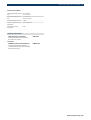
Wiring example: Isolation of separate floors
1
LSN2
LSN1
a-
a-
b+
b+
b1+
b1+
b1+
a-
a-a-
b2+b2+b2+
III
FLM-I 420-S
FLM-I 420-S
FLM-I 420-S
II
I
LSN
LSN
Pos. Description
1 Fire panel
I, II, III Floors
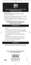
Typical wiring in a T‑Tap
b1+
b1+b1+
b1+
a-
a-a-a-
b2+
b2+b2+
b2+
FLM-I 420-SFLM-I 420-S
1
LSN
LSN
Pos. Description
1 Alarm zone / device group with LSN elements
Certifications and Approvals
Complies with EN54-17:2005
Region Certification
Germany VdS G 207045 FLM-I 420-S; FLM-I 420-D
Installation/Configuration Notes
•
National standards and guidelines must be taken into
account during the planning stage.
•
The surface-mounted housing has two cable ducts on
opposite sides:
-
2 x 2 pre-punched for diameter up to 21 mm/to
34 mm (for conduits)
-
2 x 4 rubber bushes for inserting cables with
diameters of up to 8 mm.
•
In addition, there are cable ducts on the base of the
surface-mounted housing:
-
1 x pre-punched cable ducts for diameter up to
21 mm (for conduits)
-
2 x 4 rubber bushes for inserting cables with
diameters of up to 8 mm.
•
Connectable to the fire panels FPA‑5000 Modular and
FPA‑1200 with LSN technology improved version.
Parts Included
Qty. Components
1 Short Circuit Isolator with surface-mounted housing.
1 DIN rail adapter
Note Alternatively to the use of the surface-
mounted housing, the Isolator can be
mounted on a DIN rail with the included
adapter.
Technical Specifications
Electrical
Input voltage 15 V DC to 33 V DC
Max. current consumption
•
During initialization
< 0.4 mA
•
Following the initializa-
tion
< 0.25 mA
Mechanics
LSN/Address setting 3 rotary switches for
•
Mode LSN classic or LSN improved
version
•
Automatic or manual addressing
Connections 6 threaded clamps
Housing material
•
Isolator module
PPO (Noryl)
•
Surface-mount hous-
ing
ABS/PC-Blend
Housing color
•
Isolator module
Off-white, similar to RAL 9002
•
Surface-mount hous-
ing
Signal white, RAL 9003
Dimensions Approx. 126 x 126 x 71 mm
(4.96 x 4.96 x 2.8 in.)
Weight Approx. 150 g (5.3 ounces)

FLM‑I 420‑S Short Circuit Isolator | 3
Environmental conditions
Permitted operating tempera-
ture
-20 °C to 50 °C
(-4 °F to 122 °F)
Permitted storage tempera-
ture
-25 °C to 85 °C
(-13 °F to. 176 °F)
Permitted relative humidity < 96%
Classes of equipment as per
IEC 60950
Class III equipment
Protection class as per
IEC 60529
IP 54
Ordering Information
FLM‑I 420‑S Short Circuit Isolator
for the isolation of alarm zones in which a
short circuit has occurred.
FLM-I 420-S
Accessories
FLM‑IFB126‑S Surface-mounted Housing
as retainer for the interface modules ser-
ies 420 type DIN rail (-D) or spare housing for
type surface-mount (-S)
FLM-IFB126-S
www.boschsecurity.com

4 | FLM‑I 420‑S Short Circuit Isolator
Americas:
Bosch Security Systems, Inc.
130 Perinton Parkway
Fairport, New York, 14450, USA
Phone: +1 800 289 0096
Fax: +1 585 223 9180
www.boschsecurity.us
Europe, Middle East, Africa:
Bosch Security Systems B.V.
P.O. Box 80002
5600 JB Eindhoven, The Netherlands
Phone: + 31 40 2577 284
Fax: +31 40 2577 330
www.boschsecurity.com
Asia-Pacific:
Robert Bosch (SEA) Pte Ltd, Security Systems
11 Bishan Street 21
Singapore 573943
Phone: +65 6258 5511
Fax: +65 6571 2698
www.boschsecurity.com
Represented by
© Bosch Security Systems Inc. 2010 | Data subject to change without notice
T1868129547 | Cur: en-US, V7, 16 Dec 2010
-
 1
1
-
 2
2
-
 3
3
-
 4
4


Ask a question and I''ll find the answer in the document
Finding information in a document is now easier with AI
Related papers
-
Bosch FAH-420 Quick Manual
-
Bosch F.01U.008.411 Datasheet
-
-
-
-
-
-
Bosch SM120RW User manual
-
Bosch FAP‑OC 520‑P Operating instructions
-
Other documents
-
 GreenBrook ROT4P16A Operating instructions
-
Nibe FLM 30 Installation And Maintenance Instructions Manual
-
Mitsubishi Electric MR-J5 User manual
-
Mitsubishi Melservo-J2-JR SERIES User manual
-
LG LMU18CHV Product Warranty
-
LG LAN090HSV5 Warranty
-
 Mitsubishi Electronics Stereo Amplifier MR-J2-03A5 User manual
-
Mitsubishi MR-E- A/AG User manual
-
Mitsubishi Electric MR-E-_A-QW003/AG-QW003 User manual
-

