Page is loading ...

77
iMjIIerfi
April
1993
Form:
OM-2204C
Effective
With
Serial
No.
KD41
4913
OWNERS
MANUAL
U
Read
and
follow
these
instructions
and
all
U
Give
this
manual
to
the
operator.
U
safety
blocks
carefully.
Have
only
trained
and
qualified
persons
install,
operate,
or
service
this
unit.
Callyourdistributorifyoudonotunderstand
IIlfl
U
For
help,
call
your
distributor
or:
MILLER
ELECTRIC
Mfg.
Co.,
P.O.
Box
the
directions.
1079,
Appleton,
WI
54912
414-734-9821
XMTfi
300
CC/TIG
CC/DC
Welding
Power
Source
For
GTAW,
GTAW.P,
And
SMAW
Welding
300
Amperes,
32
Volts
DC
At
60%
Duty
Cycle
Uses
Single-Phase
Or
Three-Phase
Input
Power
Protection
For
Control
Circuit,
24
VAC,
And
Overheating
U
AUTO-LINKTM
Circuitry
And
Built-In
High
Frequency
14-Pin
Remote
Control
Receptacle
cover
8/92
ST.146
123-A
PRINTED
IN
USA

~~:
MILLERS
TRUE
BLUETM
LIMITED
WARRANTY
Effective
January
1,
1992
(Equipment
with
a
serial
number
preface
of
KC
or
newer)
This
limited
warrsnty
supersedes
all
previous
MILLER
warranties
end
is
esctusive
with
no
other
guarantees
or
warranties
esprassed
or
implied.
:1~R
LIMITED
WARRANTY
Subject
to
the
terms
and
conditions
below.
MILLER
Electric
Mfg.
Co.,
Appleton.
Wisconsin,
warrants
to
its
original
retail
purchaser
that
new
MILLER
equipment
sold
after
the
effective
date
of
this
limited
warranty
is
tree
ot
de
tects
in
material
and
workmanship
at
the
time
it
is
shipped
by
MILLER.
THIS
WAR
RANTY
IS
EXPRESSLY
IN
LIEU
OF
ALL
OTHER
WARRANTIES.
EXPRESS
OR
IMPLIED,
INCLUDING
THE
WARRANTIES
OF
MERCHANTABILITY
AND
FIT
NESS.
Within
the
warranty
periods
listed
below.
MILLER
will
repair
or
replace
any
war
ranted
parts
or
components
that
tail
due
to
such
detects
in
material
or
workmanship.
MILLER
must
be
notified
in
writing
within
thirty
(30)
days
of
such
detect
or
failure,
at
which
time
MILLER
will
provide
instructions
on
the
warranty
claim
procedures
to
be
followed.
MILLER
shall
honor
warranty
claims
on
warranted
equipment
listed
below
in
the
event
of
such
a
failure
within
the
warranty
time
periods.
All
warranty
time
periods
start
on
the
date
that
the
equipment
was
delivered
to
the
original
retail
purchaser,
and
are as
follows.
5
Years
Parts
3
Years
Labor
Original
main
power
rectifiers
2
3
Years
Parts
and
Labor
Transformer/Rectifier
Power
Sources
Plasma
Arc
Cutting
Power
Sources
Semi-Automatic
and
Automatic
Wire
Feeders
*
Robots
3.
2
Years
Parts
and
Labor
Engine
Driven
Welding
Generators
(NOTE
Engines
are
warranted
separately
by
the
engine
manufacturer.)
4.
1
Year
Parts
and
Labor
Motor
Driven
Guns
Process
Controllers
Water
Coolant
Systems
HF
Units
Grids
Spot
Welders
Load
Banks
SDX
Transformers
Running
Gear/Trailers
Field
Options
(NOTE
Field
options
are
covered
under
True
BluenM
for
the
remaining
warranty
period
01
the
product
they
are
installed
in.
or
for
a
minimum
of
one
year
whichever
is
greater.)
5.
6
Months
Baneries
6.
go
Days
Parts
and
Labor
MIG
Guns/TIG
Torches
Plasma
Cutting
Torches
*
Remote
Controls
Accessory
Kits
*
Replacement
Parts
MILLERS
True
Bluene
Limited
Warranty
shall
not
apply
to:
r.
Items
furnished
by
MILLER.
but
manufactured
by
others,
such
as
engines
or
trade
accessoriea
These
items
are
covered
by
the
manufacturers
warranty,
iI
any.
2
Consumable
components:
such
as
contact
tips,
cutting
nozzles,
contactors
and
relays.
3.
Equipment
that
has
been
modified
by
any
party
other
than
MfLLER,
or
equip
ment
that
has
been
improperly
installed,
improperly
operated
or
misused
based
upon
industry
standards,
or
equipment
which
has
not
had
reasonable
and
necessary
maintenance.
or
equipment
which
has
been
used
for
operation
outside
of
the
specifications
for
the
equipment.
MILLER
PRODUCTS
ARE
INTENDED
FOR
PURCHASE
AND
USE
BY
COMMER
CIAIJINDUSTRIAL
USERS
AND
PERSONS
TRAINED
AND
EXPERIENCED
IN
THE
USE
AND
MAINTENANCE
OF
WELDING
EOUIPMENT.
In
the
event
of
a
warranty
claim
covered
by
this
warranty,
the
eaclusive
remedies
shall
be,
at
MILLERS
option:
(1)
repair:
or
(2)
replacement:
or,
where
authorized
in
writing
by
MILLER
inappropriate
cases.
(3)
the
reasonable
cost
of
repair
or
replace
ment
at
an
authorized
MILLER
service
station,
or
(4)
payment
of
or
credit
for
the
pur
chase
price
(less
reasonable
depreciation
based
upon
actual
use)
upon
return
of
the
goods
at
customers
risk
and
espense
MILLERS
option
of
repair
or
replacement
will
be
FOB..
Factory
at
Appleton.
Wisconsin.
or
F.O
B.
ala
MILLER
authorized
ser
vice
facility
as
determined
by
MILLER.
Therefore
no
compensation
or
reimburse
ment
for
transportation
costs
of
any
kind
will
be
allowed.
TO
THE
EXTENT
PERMITTED
BY
LAW.
THE
REMEDIES
PROVIDED
HEREIN
ARE
THE
SOLE
AND
EXCLUSIVE
REMEDIES.
IN
NO
EVENT
SHALL
MILLER
BE
LIABLE
FOR
DIRECT.
INDIRECT.
SPECIAL.
INCIDENTAL
OR
CONSEQUENTIAL
DAMAGES
(INCLUDING
LOSS OF
PROFIT),
WHETHER
BASED
ON
CON
TRACT,
TORT
OR
ANY
OTHER
LEGAL
THEORY
ANY
EXPRESS
WARRANTY
NOT
PROVIDED
HEREIN
AND
ANY
IMPLIED
WAR
RANTY,
GUARANTY
OR
REPRESENTATION
AS
TO
PERFORMANCE.
AND
ANY
REMEDY
FOR
BREACH
OF
CONTRACT
TORT
OR
ANY
OTHER
LEGAL
THEORY
WHICH.
BUT
FOR
THIS
PROVISION.
MIGHT
ARISE
BY
IMPLICATION.
OPERATION
OF
LAW,
CUSTOM
OF
TRADE
OR
COURSE
OF
DEALING,
IN
CLUDING
ANY
IMPLIED
WARRANTY
OF
MERCHANTABILITY
OR
FITNESS
FOR
PARTICULAR
PURPOSE,
WITH
RESPECT
TO
ANY
AND
ALL
EQUIPMENT
FURNISHED
BY
MILLER
tS
EXCLUDED
AND
DISCLAIMED
BY
MILLER.
Some
slates
in
the
U.S-A.
do
nol
allow
limitations
of
how
long
an
implied
warranty
lasts,
or
the
esciusion
of
incidental,
indirect.
special
or
consequential
damages.
so
the
above
limitation
or
eaclusion
may
not
apply
to
you.
This
warranty
provides
spe
cific
legal
rights,
and
other
rights
may
be
available,
but
may
vary
from
slate
to
slate.
In
Canada,
legislation
in
some
provinces
provides
for
certain
additional
warranties
or
remedies
other
than
as
staled
herein,
and
to
the
ealehl
that
they
may
not
be
waived.
the
limitations
and
eecluaions
sal
out
above
may
not
apply.
This Limited
Warranty
provides
specific
legal
rights.
and
other
rights
may
be
available.
bul
may
very
Irom
province
to
province.
:i~U
RECEIVING-HANDLING
BefDrB
unpacking
equipment,
Check
carton
for
any
damage
that
may
have
occurred
during
shipment.
File
any
claims
for
loss
or
damage
with
the
delivering
carrier.
Assistance
for
filing
or
settling
claims
may
be
obtained
from
distributor
and/or
equipment
manufacturers
Transportation
Department.
When
requesting
information
about
this
equipment,
always
provide
Model
Designation
and
Serial
or
Style
Number.
Use
the
following
spaces
to
record
Model
Designation
and
Serial
or
Style
Number
of
your
unit.
The
information
is
located
on
the
rating
label
or
nameplate.
Model
_________
Serial
or
Style
No.
Date
of
Purohase
miller
5/93

ARC
WELDING
SAFETY
PRECAUTiONS
5.
Properly
install
and
ground
this
equipment
according
to
its
Owners
Manual
and
national,
state,
and
local
codes.
6.
When
making
input
connections,
attach
proper
grounding
conductor
first.
7.
Turn
off
all
equipment
when
not
in
use.
8.
Do
not
use
worn,
damaged,
undersized,
or
poorly
spliced
cables.
9.
Do
not
wrap
cables
around
your
body.
10.
Ground
the
workpiece
to
a
good
electrical
(earth)
ground.
11.
Do
not
touch
electrode
if
in
contact
with
the
work
or
ground.
12.
Use
only
well-maintained
equipment.
Repair
or
replace
damaged
parts
at
once.
13.
Wear
a
safety
harness
if
working
above
floor
level.
14.
Keep
all
panels
and
covers
securely
in
place.
a
WARNING
ARC
WELDING
can
be
hazardous.
PROTECT
YOURSELF
AND
OTHERS
FROM
POSSIBLE
SERIOUS
INJURY
OR
DEATH.
KEEP
CHILDREN
AWAY.
PACEMAKER
WEARERS
KEEP
AWAY
UNTIL
CONSULTING
YOUR
DOCTOR.
In
welding,
as
in
most
jobs,
exposure
to
certain
hazards
occurs.
Welding
is
safe
when
precautions
are
taken.
The
safety
information
given
below
is
only
a
summary
of
the
more
complete
safety
information
that
will
be
found
in
the
Safety
Standards
listed
on
the
next
page.
Read
and
follow
all
Safety
Standards.
HAVE
ALL
INSTALLATION,
OPERATION,
MAINTENANCE,
AND
REPAIR
WORK
PERFORMED
ONLY
BY
QUALIFIED
PEOPLE.
ELECTRIC
SHOCK
can
kill.
Touching
live
electrical
parts
can
cause
fatal
shocks
or
severe
burns.
The
electrode
and
work
circuit
is
electrically
live
whenever
the
output
is
on.
The
input
power
circuit
and
machine
internal
circuits
are
also
live
when
power
is
on.
In
semiautomatic
or
automatic
wire
welding,
the
wire,
wire
reel,
drive
roll
housing,
and
all
metal
parts
touching
the
welding
wire
are
electrically
live,
Incorrectly
installed
or
improperly
grounded
equipment
is
a
hazard.
1.
Do
not
touch
live
electrical
parts.
2.
Wear
dry,
hole-free
insulating
gloves
and
body
protection.
3.
Insulate
yourself
from
work
and
ground
using
dry
insulating
mats
or
covers.
4.
Disconnect
input
power
or
stop
engine
before
installing
or
servicing
this
equipment.
ARC
RAYS
can
burn
eyes
and
skin;
~
NOISE
can
damage
hearing.
Arc
rays
from
the
welding
process
produce
intense
heat
and
strong
ultraviolet
rays
that
can
burn
eyes
and
skin.
Noise
from
some
processes
can
damage
hearing.
NOISE
ARC
RAYS
2.
Wear
a
welding
helmet
fitted
with
a
proper
shade
of
filter
(see
ANSI
Z49.
I
listed
in
Safety
Standards)
to
protect
your
face
and
eyes
when
welding
or
watching.
3.
Wear
approved
safety
glasses.
Side
shields
recommended.
4.
Use
protective
screens
or
barriers
to
protect
others
from
flash
and
glare;
warn
others
not
to
watch
the
arc.
5.
Wear
protective
clothing
made
from
durable,
flame-resistant
1.
Use
approved
ear
plugs
or
ear
muffs
if
noise
level
is
high.
material
(wool
and
leather)
and
foot
protection.
FUMES
AND
GASES
can
be
hazardous
to
your
health.
Welding
produces
fumes
and
gases.
Breathing
these
fumes
and
gases
can
be
hazardous
to
your
health.
5.
Work
in
a
confined
space
only
if
it
is
well
ventilated,
or
while
wearing
an
air-supplied
respirator.
Shielding
gases
used
for
welding
can
displace
air
causing
injury
or
death.
Be
sure
the
breathing
air
is
safe.
a.~.
6.
Do
not
weld
in
locations
near
degreasing,
cleaning,
or
spraying
1.
Keep
your
head
out
of
the
fumes.
Do
not
breathe
the
fumes.
2.
If
inside,
ventilate
the
area
and/or
use
exhaust
at
the
arc
to
operations.
The
heat
and
rays
of
the
arc
can
react
with
vapors
to
form
highly
toxic
and
irritating
gases.
remove
welding
fumes
and
gases.
7.
Do
not
weld
on
coated
metals,
such
as
galvanized,
lead,
or
3.
If
ventilation
is
poor,
use
an
approved
air-supplied
respirator.
cadmium
plated
steel,
unless
the
coating
is
removed
from
the
4.
Read
the
Material
Safety
Data
Sheets
(MSDS5)
and
the
weld
area,
the
area
is
well
ventilated,
and
if
necessary,
while
manufacturers
instruction
for
metals,
consumables,
coatings,
wearing
an
air-supplied
respirator.
The
coatings
and
any
metals
and
cleaners,
containing
these
elements
can
give
off
toxic
fumes
if
welded.
WELDING
can
cause
fire
or
explosion.
5.
Watch
for
fire,
and
keep
a
fire
extinguisher
nearby.
Sparks
and
spatter
fly
off
from
the
welding
arc.
The
flying
sparks
and
hot
metal,
weld
spatter,
hot
6.
Be
aware
that
welding
on
a
ceiling,
floor,
bulkhead,
or
partition
can
cause
fire
on
the
hidden
side.
workpiece,
and
hot
equipment
can
cause
fires
and
burns.
Accidental
contact
of
electrode
or
welding
wire
7.
Do
not
weld
on
closed
containers
such
as
tanks
or
drums.
to
metal
objects
can
cause
sparks,
overheating,
or
fire.
8.
Connect
work
cable
to
the
work
as
close
to
the
welding
area
as
practical
to
prevent
welding
current
from
traveling
long,
possibly
1.
Protect
yourself
and
others
from
flying
sparks
and
hot
metal.
2.
Do
not
weld
where
flying
sparks
can
strike
flammable
material.
9.
unknown
paths
and
causing
electric
shock
and
fire
hazards.
Do
not
use
welder
to
thaw
frozen
pipes.
3.
Remove
all
flammables
within
35
ft
(10.7
m)
of
the
welding
arc.
If
this
is
not
possible,
tightly
cover
them
with
approved
covers,
10.
Remove
stick
electrode
from
holder
or
cut
off
welding
wire
at
contact
tip
when
not
in
use.
4.
Be
alert
that
welding
sparks
and
hot
materials
from
welding
can
easily
go
through
small
cracks
and
openings
to
adjacent
areas.
11.
Wear
oil-free
protective
garments
such
as
leather
gloves,
heavy
shirt,
cuffless
trousers,
high
shoes,
and
a
cap.
>j
FLYING
SPARKS
AND
HOT
METAL
can
cause
injury,
I
Chipping
and
grinding
cause
flying
metal.
As
welds
cool,
they
can
throw
off
slag.
1.
2.
Wear
approved
face
shield
or
safety
goggles.
Side
shields
recommended.
Wear
proper
body
protection
to
protect
skin.
en
9192

CYLINDERS
can
explode
if
damaged.
Shielding
gas
cylinders
contain
gas
under
high
pressure.
If
damaged,
a
cylinder
can
explode.
Since
gas
cylinders
are
normally
part
of
the
welding
process,
be
sure
to
treat
them
carefully.
1.
Protect
compressed
gas
cylinders
from
excessive
heat,
mechanical
shocks,
and
arcs.
2.
Install
and
secure
cylinders
in
an
upright
position
by
chaining
them
to
a
stationary
support
or
equipment
cylinder
rack
to
prevent
falling
or
tipping.
-
____________________
3.
Keep
cylinders
away
from
any
welding
or
other
electrical
circuits.
4.
Never
allow
a
welding
electrode
to
touch
any
cylinder.
5.
Use
only
correct
shielding
gas
cylinders,
regulators,
hoses,
and
fittings
designed
for
the
specific
application;
maintain
them
and
associated
parts
in
good
condition.
6.
Turn
face
away
from
valve
outlet
when
opening
cylinder
valve.
7.
Keep
protective
cap
in
place
over
valve
except
when
cylinder
is
in
use
or
connected
for
use.
8.
Read
and
follow
instructions
on
compressed
gas
cylinders.
associated
equipment,
and
CGA
publication
P-i
listed
in
Safety
Standards.
ENGINE
EXHAUST
GASES
can
kill.
1.
Use
equipment
outside
in
open,
well-ventilated
areas.
2.
If
used
in
a
closed
area,
vent
engine
exhaust
outside
and
Engines
produce
harmful
exhaust
gases.
away
from
any
building
air
intakes.
ENGINE
FUEL
can
cause
fire
or
1.
Stopenginebeforecheckingoraddingfuel.
explosion.
2.
Do
not
add
fuel
while
smoking
or
if
unit
is
near
any
sparks
or
open
flames.
3.
Allow
engine
to
cool
before
fueling.
If
possible,
check
and
add
Engine
fuel
is
highly
flammable,
fuel
to
cold
engine
before
beginning
job.
4.
Do
not
overfill
tank
allow
room
for
fuel
to
expand.
5.
Do
not
spill
fuel.
If
fuel
is
spilled,
clean
up
before
starting
engine.
SPARKS
can
cause
BATTERY
GASES
1.
Always
wear
a
face
shield
when
working
on
a
battery.
TO
EXPLODE;
BATTERY
ACID
can
2.
Stop
engine
before
disconnecting
or
connecting
battery
burn
eyes
and
skin,
cables.
Batteries
contain
acid
and
generate
explosive
3.
4.
Do
not
allow
tools
to
cause
sparks
when
working
on
a
battery.
Do
not
use
welder
to
charge
batteries
or
jump
start
vehicles.
ases.
5.
Observe
correct
polarity
(+
and
)
on
batteries.
PRINCIPAL
SAFETY
STANDARDS
Safety
in
Welding
and
Cutting,
ANSI
Standard
Z49.1,
from
American
Welding
Society,
550
N.W.
LeJeune
Rd.
Miami
FL
33126
Safety
and
Health
Standards,
OSHA
29
CFR
1910,
from
Superinten
dent
of
Documents,
U.S.
Government
Printing
Office,
Washington,
D.C.
20402.
Recommended
Safe
Practices
for
the
Preparation
for
Welding
and
Cutting
of
Containers
That
Have
Held
Hazardous
Substances,
Ameri
can
Welding
Society
Standard
AWS
F4.1,from
American
Welding
So
ciety,
550
N.W.
LeJeune
Rd.
Miami,
FL
33126
National
Electrical
Code,
NFPA
Standard
70,
from
National
Fire
Pro
tection
Association,
Batterymarch
Park,
Quincy,
MA
02269.
Safe
Handling
of
Compressed
Gases
in
Cylinders,
CGA
Pamphlet
P-i,
from
Compressed
Gas
Association,
1235
Jefferson
Davis
High.
way,
Suite
501,
Arlington,
VA
22202.
Code
for
Safety
in
Welding
and
Cutting,
CSA
Standard
Wi
17.2,
from
Canadian
Standards
Association,
Standards
Sales,
178
Rexdale
Bou
levard,
Rexdale,
Ontario,
Canada
M9W
1
R3.
Safe
Practices
For
OccupationAnd
Educational
EyeAnd
Face
Protec
tion,
ANSI
Standard
Z87.1,
ftom
American
National
Standards
institute.
1430
Broadway,
New
York,
NY
10018.
Cutting
And
Welding
Processes,
NFPA
Standard
51
B,
from
National
Fire
Protection
Association,
Batteryrnarch
Park,
Quincy,
MA
02269.
a
WARNING
ENGINES
can
be
hazardous.
MOVING
PARTS
can
cause
injury.
~
Moving
parts,
such
as
fans,
rotors,
and
belts
can
cut
fingers
and
hands
and
catch
loose
clothing,
1.
Keep
all
doors,
panels,
covers,
and
guards
closed
and
securely
in
place.
3.
4.
5.
6.
Have
only
qualified
people
remove
guards
or
covers
for
To
prevent
accidental
starting
during
servicing,
disconnect
maintenance
and
troubleshooting
as
necessary.
negative
()
battery
cable
from
battery.
Keep
hands,
hair,
loose
clothing,
and
tools
away
from
moving
parts.
Reinstall
panels
or
guards
and
close
doors
when
servicing
is
2.
Stop
eng
ne
before_installing_or_connecting_unit,
finished
and
before_starting_engine.
fr.
~
.~
(~\
,
STEAM
AND
COOLANT
can
skin.
The
coolant
in
the
r
under
pressure.
PRESSURIZED
burn
face,
eyes,
adiator
can
be
very
h
HOT
and
ot
and
1.
2.
3.
Do
not
remove
radiator
cap
when
engine
is
hot.
Allow
engine
to
cool.
Wear
gloves
and
put
a
rag
over
cap
area
when
removing
cap.
Allow
pressure
to
escape
before
completely
removing
cap.
sri
9/92

EMF
INFORMATION
TABLE
OF
CONTENTS
SECTION
1
SAFETY
INFORMATION
SECTION
2
SPECIFICATIONS
2-1.
Volt-Ampere
Curves
2
2-2.
Duty
Cycle
2
SECTION
3INSTALLATION
Typical
Process
Connections
3
Selecting
A
Location
And
Moving
Welding
Power
Source
Selecting
And
Preparing
Weld
Output
Cables
Connecting
To
Weld
Output
Receptacles
Remote
14
Receptacle
Information
And
Connections
Installing
Gas
Supply
Connecting
Input
Power
SECTION
4OPERATION
9
SECTION
5-
MAINTENANCE
&
TROUBLESHOOTING
5-1.
Routine
Maintenance
5-2.
Removing
Case
And
Measuring
Input
Capacitor
Voltage
5-3.
Overload
Protection
5-4.
Changing
AmperageNoltage
Meter
Hold
Function
5-5.
Troubleshooting
SECTION
6
ELECTRICAL
DIAGRAMS
20
SECTION
7
TUNGSTEN
ELECTRODE
7-1.
Selecting
Tungsten
Electrode
28
7-2.
Preparing
Tungsten
29
SECTION
8
HIGH
FREQUENCY
30
SECTION
9
PARTS
LIST
Figure
9-1.
Main
Assembly
(208-230/460
V
Model
Illustrated)
Figure
9-2.
Chassis,
Mid
(208-230/460V
Model
Illustrated)
Figure
9-3.
Panel,
Front
w/Components
N
OTE
~
.1
Considerations
About
Magnetic
Fields
The
following
is
a
quotation
from
the
General
Conclusions
Section
Welding
And
The
Effects
Of
Low
Frequency
Electric
And
To
reduce
magnetic
fields
in
the
workplace,
use
the
following
of
the
U.S.
Congress,
Office
of
Technology
Assessment,
Biological
procedures:
Effects of
Power
Frequency
Electric
&
Magnetic
Fields
Background
Paper,
OTA-BP-E-53
(Washington,
DC:
U.S.
Government
Printing
Office,
May
1989):
.
. .
there
is
now
a
very
1.
Keep
cables
close
together
by
twisting
or
taping
them.
2.
Arrange
cables
to
one
side
and
away
from
the
operator.
large
volume
of
scientific
findings
based
on
experiments
at
the
3.
Do
not
coil
or
drape
cables
around
the
body.
cellular
level
and
from
studies
with
animals
and
people
which
clearly
establish
that
low
frequency
magnetic
fields
can
interact
with,
and
produce
changes
in,
biological
systems.
While
most
of
this
work
is
of
very
high
quality,
the
results
are
complex.
Current
scientific
understanding
does
not
yet
allow
us
to
interpret
the
evidence
in
a
4.
Keep
welding
power
source
and
cables
as
far
away
as
practical.
5.
Connect
work
clamp
to
workpiece
as
close
to
the
weld
as
possible.
single
coherent
framework.
Even
more
frustrating,
it
does
not
yet
About
Pacemakers:
allow
us
to
draw
definite
conclusions
about
questions
of
possible
The
above
procedures
are
among
those
also
normally
risk
or
to
offer
clear
science-based
advice
on
strategies
to
minimize
recommended
for
pacemaker
wearers.
Consult
your
doctor
for
or
avoid
potential
risks.
complete
information.
dlO
4/93
3-1.
3-2.
3-3.
3-4.
3-5.
3-6.
3-7.
4
5
6
6
7
8
15
16
17
17
18
32
36
38
OM-2204C
4/93


SECTION
1
SAFETY
IN
FORMATION
Figure
1.~1.
Safety
Information
1
Safety
Alert
Symbol
2
Signal
Word
WARNING
means
possible
death
or
serious
injury
can
happen.
CAUTION
means
possible
minor
injury
or
equipment
damage
can
happen.
3
Statement
Of
Hazard
And
Result
4
Safety
Instructions
To
Avoid
5
Hazard
Symbol
(If
Available)
6
Safety
Banner
Read
safety
blocks
for
each
sym
bol
shown.
7
NOTE
Special
instructions
for
best
oper
ation
not
related
to
safety.
SECTION
2
SPECIFICATIONS
Table
2-1.
Welding
Power
Source
Read
all
safety
messages
throughout
this
manual.
Obey
all
safety
messages
to
avoid
injury.
Learn
the
meaning
of
WARNING
and
CAUTION.
2
modl,l
2/93
2
\
CAUTION
________
3
________
L
~
ELECTRIC
SHOCK
can
kiII.~
MOVING
PARTS
can
inlure.
Do
not
touch
live
electrical
parts.
Keep
away
from
moving
parts
I
Disconnect
input
power
before
nstalling
or
servicing
J~
~
f<eep
all
panels
and
covers
closed
I
when
operating.
I
/
5
READ
SAFETY
BLOCKS
at
start
of
Section
3-1
before
proceeding.
NOTE
~
Turn Off
switch
when
using
high
frequency.
Hazard
Specification
Description
Constant
Current/Direct
Current
(CC/DC)
Gas
Tungsten
Arc
(GTAW),
Gas
Tungsten
Arc
-
Pulsed
(GTAW-P),
Shielded
Metal
Arc
Welding
(SMAW)
l2ft(3.7m)
Length:
21-3/4
in
(522
mm);
Width:
12
in
(305
mm);
Height:
17-3/8
in
(441
mm)
Net:
84
lb
(38
kg);
Ship:
89
lb
(40
kg)
See
Rear
Cover
Type
Of
Output
Welding
Processes
Input
Power
Cord
Overall
Dimensions
Weight
Options
Rated
Weld
Output
Type
Of
Input
Input
Amperes
At
Rated
Output
KVAIKW
Used
At
Rated
Output
Amperage
Range
Max.
Open-Circuit
Voltage
With
Three-Phase
Input
With
Single-Phase
Input
300
Amperes,
32
Volts
DC
At
60%
Duty Cycle
(See
Section
2-2)
230, 460,
Or
575
Volts
AC;
50/60
Hz
42AAt230V,21
AAt46OV,
164AAt575V
16.1
kVA111.3kW
5-375
A
80
Volts
DC
225
Amperes,
29
Volts
DC
At
60%
Duty
Cycle
(See
Section
2-2)
230, 460,
Or
575
Volts
AC;
50/60
Hz
50.8
A
At
230
V,
29
A
At
460
V,
23.6
A
At
575
V
12.8
kVAJ7.8
kW
5-225
A
80
Volts
DC
OM-2204
Page
1

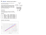
2-1.
Volt-Ampere
Curves
Figure
2-1
-
Volt-Ampere
Curves
2-2.
Duty
Cycle
a
CAUTION
600
600
400
Cl)
LU
a.
(
200
a
-J
LU
160
0
~
3
PHASE
OPERATION
SINGLE
PHASE
OPERATION
Figure
2-2.
Duty
Cycle
Chart
100
90
80
70
The
volt-ampere
curves
show
the
minimum
and
maximum
voltage
and
amperage
output
capabilities
of
the
welding
power
source.
Curves
of
other
settings
fall
be
tween
the
curves
shown.
A.
230/460
Volt
Models
B.
460/575
Volt
Models
100
go
80
70
60
~
SMAW
MAX.
40
30
30
20
20
10
0
~
-
0
0
100
200
300
400
400
AMPERES
ssbl
.110/91
SB-136
507/
SB-141
457
60
-
OTAW
_
MIN.
50
575
460
ARC
CONTROL
OZ
26X
50X
75X
~00x
OTAW
MIN.
10
ARC
CONTROL
0
300
AMPERES
EXCEEDING
DUTY
CYCLE
RATINGS
will
damage
unit.
Do
not
exceed
indicated
duty
cycles.
waml.1
V92
Duty
cycle
is
how
long
the
unit
can
operate
within
a
ten
minute
period
without
causing
overheating
or
damage.
This
unit
is
rated
at
60%
duty
cycle
when
operated
at
300
amperes
from
three-phase
input
power,
or
at
225
amperes
from
single-phase
input
power.
This
allows
welding
6
minutes
out
of
every
10
minutes.
~3
16
20
~30
40
60I0~e090~0
%
DUTY
CYCLE
sbl.r
10191
/
SB136
510
OM-2204
Page
2

SECTION
3INSTALLATION
a
WARNING
HIGH-FREQUENCY
RADIATION
can
interfere
with
radio
navigation,
safety
services,
computers,
and
communications
equipment.
Have
only
qualified
person
familiar
with
electronic
equipment
perform
this
installation.
Read
and
follow
entire
Section
8
for
proper
location
and
installation
requirements
for
high-frequency
equipment
before
installing
unit.
Figure
3-1.
Typical
Process
Connections
3-1.
Typical
Process
Connections
Remote
14
Pin
Work
+
GTAW
Pulse
Control
Scratch
Start
Pulsed
GTAW
Or
GTAW
+
–
OM-2204
Page
3

3-2.
Selecting
A
Location
And
Moving
Welding
Power
Source
a
WARNING
ELECTRIC
SHOCK
can
kill.
Do
not
touch
live
electrical
parts.
Disconnect
input
power
conductors
from
deenergized
supply
line
BEFORE
moving
welding
power
source.
FIRE
OR
EXPLOSION
can
result
from
placing
unit
on,
over,
or
near
combustible
surfaces.
Do
not
locate
unit
on,
over,
or
near
combustible
surfaces.
Do
not
install
unit
near
flammables.
BLOCKED
AIRFLOW
causes
overheating
and
possible
damage
to
unit.
Do
not
block
or
filter
airflow.
Warranty
is
void
if
any
type
of
filter
is
used.
r
~
~
FUMES
can
be
hazardous;
LACK
OF
FRESH
AIR
AND
PROPER
VENTILATION
can
be
harmful.
Do
not
breathe
welding
fumes.
Place
unit
only
where
there
is
a
good
fresh
air
supply
and
proper
ventilation.
FALLING
EQUIPMENT
can
cause
serious
personal
injury
and
equipment
damage.
Lift
unit
at
handles.
Have
two
persons
of
adequate
physical
strength
lift
unit.
Move
unit
with
hand
cart
or
similar
device
of
adequate
capacity.
If
using
a
fork
lift
vehicle,
secure
unit
on
a
proper
skid
before
transporting.
swarnhli
2/92
Figure
3-2.
Location
And
Movement
Of
Welding
Power
Source
2
3
1
3
in
(78
mm)
Open
Space
At
Sides,
6
in
(156
mm)
At
Rear
For
Good
Airflow
2
Lifting
Handles
Use
handles
to
move
unit.
3
Rating
Label
Locate
unit
near
correct
input
pow
er
supply.
ST.146
123-A
/
Ref.
5T-151
556
OM-2204
Page
4

3-3.
Selecting
And
Preparing
Weld
Output
Cables
Table
3-1.
Weld
Cable
Size*
Welding
Amperes
100
150
200
250
Total
Cable
(Copper)
Length
In
Weld
Circuit
Not
Exceeding
lOOft(30m)Or
Less
150ft
I
200ft
I
250ff
I
300ff
I
350ff
I
400ft
(45m)
(60m)
(70m)
(90m)
(105m)
(120m)
10
To
60%
Duty
Cycle
4
3
3
2
60
Thru
100%
Duty
Cycle
4
3
2
1
10
Thru
100%
Duty
Cycle
4
3
2
1
1/0
1/0
2
1
1/0
2/0
3/0
3/0
1
1/0
2/0
3/0
4/0
4/0
1/0
2/0 3/0 4/0
2-2/0
2-2/0
300
350
400
500
1
1/0
1/0
2/0
1/0
2/0
2/0
3/0
2/0
3/0
3/0
4/0
3/0
4/0
4/0
2-2/0
4/0
2-2/0
2-2/0
2-3/0
2-2/0
2-3/0
2-3/0
2-4/0
2-3/0
2-3/0
2-4/0
3-3/0
2-3/0
2-4/0
2-4/0
3-3/0
*WeId
cable
size
(AWG)
is
based
on
either
a
4
volts
or
less
drop
or
a
current
density
of
not
more
than
300
circular
mils
per
ampere.
s-oooi-c
OM-2204
Page
5
6
Tools
Needed:
1
Weld
Output
Cable
Determine
total
cable
length
in
weld
Circuit
and
maximum
welding
amperes.
Use
Table
3-1
to
select
proper
cable
size.
Use
shortest
cables
possible.
Do
not
use
damaged
cables.
2
Terminal
Lug
Use
lugs
of
proper
amperage
capacity
and
hole
size
for
connect
ing
to
work
clamp
or
electrode
hold
er.
3
Insulated
Electrode
Holder
4
GTAW
Torch
Install
according
to
manufacturers
instructions.
5
Work
Clamp
Install
onto
work
cable.
6
Dinse-Type
Connector
Install
onto
weld
cable
as
shown
in
Figure
3-4.
sber
11192
S-0056
5
For
Example,
Total
Cable
Length
In
Weld
Circuit
=
20
ft
(6
m)
Figure
3-3.
Selecting
And
Preparing
Weld
Output
Cables
1
Weld
Output
Cable
2
Handle
3
Sleeve
Slide
handle
onto
cable;
strip
cable
and
install
sleeve.
4
Connector
Body
3
Tools
Needed:
5
Setscrew
Insert
cable
with
sleeve
fully
into
connector
body,
tighten
setscrew,
and
slide
handle
over
connector.
If
job
requires
cable
larger
than
3/0
AWG,
use
2
ft
(610mm)
or
shorter
piece
of
3/0
AWG
cable
for
Dinse
Type
connector
installation.
Con
nect
other
end
of
short
cable
to
the
4/0
or
larger
weld
cable.
Figure
3-4.
Dinse-Type
Connector
Assembly
ST-156
496

3-4.
Connecting
To
Weld
Output
Receptacles
a
WARNING
ELECTRIC
SHOCK
can
kill;
ARCING
can
burn
skin
or
damage
electrical
equipment.
Do
not
touch
live
electrical
parts.
Turn
Off
welding
power
source
before
making
any
weld
output
connections.
Do
not
change
position
of
welding
cable
connectors
while
welding.
Be
sure
connectors
are
secure
in
receptacles
before
welding.
1
Positive
(+)
Weld
Output
Receptacle
2
Negative
()
Weld
Output
Receptacle
3
Connector
For
DC
Electrode
Positive
(DCEP),
connect
work
cable
connector
to
negative
()
receptacle
and elec
trode
holder
cable
connector
to
positive
(+)
receptacle.
For
DC
Electrode
Negative
(DCEN),
reverse
cable
connec
tions.
See
Figure
3-1
for
typical
polarity
choices.
To
connect
to
receptacle,
align
key-
way,
insert
connector,
and
turn
clockwise
until
tight.
3-5.
Remote
14
Receptacle
Information
And
Connections
Figure
3-6.
Remote
14
Connections
swami
22
2/9~
2
Figure
3-5.
Connecting
To
Weld
Output
Receptacles
Ret.
ST-155
091
/
Ret.
ST-153
625
1
2
1
Remote
14
Receptacle
RC2
2
Keyway
3
Plug
4
Threaded
Collar
To
connect
th
this
receptacle,
align
keyway,
insert
plug,
and
tighten
threaded
collar.
Socket
Information:
Remote
Contactor
A
24
volts
ac.
Protected
by
fuse
F2.
B
Contact
closure
to
pin
A
completes
24
volts
ac
contactor
control
circuit.
Remote
AmperageNoltage
Control
C
Command
reference;
+10
volts
dc.
D
Control
circuit
common.
E
Input
command
signal
(potentiometerwiper
or
0
to
+
10
volts
dc).
K
Chassis
common.
The
remaining
sockets
are
not
used.
sb7
18/92
Ret.
ST-i
53625
/
Ret.
S-0004-A
/
S-0750
OM-2204
Page
6

3-6.
Installing
Gas
Supply
CYLINDERS
can
explode
if
damaged.
Keep
cylinders
away
from
welding
and
other
electrical
circuits.
Never
touch
cylinder
with
welding
electrode.
Always
secure
cylinder
to
running
gear,
wall,
or
other
stationary
support.
r
GAS
IN
warn4.1
9/91
Obtain
gas
cylinder
and
chain
to
running
gear,
wall,
or
other
station
ary
support
so
cylinder
cannot
fall
and
break
oft
valve.
1
Cap
2
Cylinder
Valve
Remove
cap,
stand
to
side
of
valve,
and
open
valve
slightly.
Gas
flow
blows
dust
and
dirt
from
valve.
Close
valve.
3
Cylinder
4
Regulator/Flowmeter
Install
so
face
is
vertical.
5
Gas
Hose
Connection
Fitting
has
5/8-18
right-hand
threads.
6
Flow
Adjust
Typical
flow
rate
is
20
cfh
(cubic
feet
per
hour).
Check
wire
man
ufacturers
recommended
flow
rate.
7
CO2
Adapter
8
0-Ring
Install
adapter
with
0-ring
between
regulator/flowmeter
and
CO2
cylinder.
9
Gas
In
Fitting
(Rear
Of
Unit)
10
Gas
Out
Fitting
(Front
Of
Unit)
The
Gas
In
and
Gas
Out
fittings
have
5/8-18
right
hand
threads.
Obtain
proper
size,
type,
and
length
hose
and
make
connections
as
follows:
Connect
hose
from
shielding
gas
supply
regulator/flowmeter
to
Gas
In
fitting.
Connect
shielding
gas
hose
from
3
torch
to
Gas
Out
fitting.
a
WARNING
.
BUILDUP
OF
SHIELDING
GAS
can
harm
health
or
kill.
Shutoff
shielding
gas
supply
when
not
in
use.
5
2
I--
I
3
OR
Argon
Gas
4
2
9
CO2
Gas
Tools
Needed:
~
1-1/8,5/8
in
ssb3.
I
*
12/92
ST~158
697-A
/
Ref.
S.0004.A
/
Ref.
ST-I
53625
/
~f
~.o5~1
.~
Figure
3-7.
Typical
Regulator/Flowmeter
Installation
OM-2204
Page
7

3-7.
Connecting
Input
Power
HIGH-FREQUENCY
RADIATION
can
interfere
with
radio
navigation,
safety
services,
computers,
and
communications
equipment.
Have
only
qualified
person
familiar
with
electronic
equipment
periorm
this
installation.
Read
and
follow
entire
Section
8
for
proper
location
and
installation
requirements
for
high-frequency
equipment
before
installing
unit.
ELECTRIC
SHOCK
can
kill.
Do
not
touch
live
electrical
parts.
Turn
Off
welding
power
source,
and
disconnect
input
power
before
inspecting
or
installing.
Have
only
qualified
persons
install
unit.
Installation
must
meet
National
Electrical
Code
and
all
other
codes.
Have
only
qualified
persons
make
this
installation.
1
Rating
Label
Use
single
or
three-phase,
50/60
Hz,
ac
input
power
which
matches
one
of
the
voltages
shown.
The
AUTO-LINK
circuitry
senses
the
in
put
voltage
and
automatically
links
the
unit
for
operation.
2
Line
Disconnect
Device
Of
Proper
Rating
3
Input
Power
Cord
4
Grounding
Conductor
Green
Or
Green
With
Yellow
Stripe(s)
Install
input
conductors
and
grounding
conductor
from
unit
to
deenergized
line
disconnect
device.
Be
sure
grounding
conductor
goes
to
an
earth
ground.
5
Black
And
White
Input
Con
ductor
6
Insulation
Sleeving
7
Electrical
Tape
8
Red
Input
Conductor
Red
conductor
not
used
in
single-
phase
system.
Insulate
and
isolate
conductor
by
sliding
insulation
sleeving
over
end
of
lead,
bending
lead
back,
and
taping
to
power
cord.
9
Overcurrent
Protection
Select
fuses
or
Circuit
breakers
us
ing
Table
3~2.
Install
into
deener
gized
line
disconnect
device
(fused
disconnect
switch
shown).
Pet.
ST144
221
/
Ret
ST.070
399-C
/
Ret.
ST-146
123-A
/
5-0657
/
Ret.
S-0092-A
Figure
3-8.
Location
And
Input
Power
Connections
A
WARNING
Three-Phase
System
.
Single-Phase
System
2
4
9
OM-2204
Page
8

Table
3-2.
Electrical
Service
Requirements*
Three-Phase
230
460
575
Single-Phase
230 460
575
Rated
Output
42
21
16.4
50.8
29
23.6
Fuse
Or
In
Amperes
60 30
25
80
40
35
These
values
are
calculated
from
the
1990
edition
of
the
National
Electrical
Code
(NEC).
1
Recommended
fuse
or
circuit
breaker
size
is
that
closest
to
150%
of
rated
input
amperage
of
the
welding
power
source.
Article
630-12(a)
of
NEC
allows
fuse
or
circuit
breaker
sizing
up
to
200%
of
rated
input
amperage.
Res.
S-0092-F
SECTION
4OPERATION
a
WARNING
ELECTRIC
SHOCK
can
kill.
Always
wear
dry
insulating
gloves.
Insulate
yourself
from
work
and
ground.
Do
not
touch
live
electrical
parts.
Keep
all
panels
and
covers
securely
in
place
FUMES
AND
GASES
can
be
hazardous
to
your
health.
Keep
your
head
out
of
the
fumes.
Ventilate
area,
or
use
breathing
device.
Read
Material
Safety
Data Sheets
(MSDSs)
and
manufacturers
instructions
for
material
used.
WELDING
can
cause
fire
or
explosion.
Do
not
weld
near
flammable
material.
Watch
for
fire;
keep
extinguisher
nearby.
Do
not
locate
unit
over
combustible
surfaces.
Do
not
weld
on
closed
containers.
Allow
work
and
equipment
to
cool
before
handling.
,~
~
~
ARC
RAYS
can
burn
eyes
and
skin;
NOISE
can
damage
hearing.
Wear
welding
helmet
with
correct
shade
of
filter.
Wear
correct
eye,
ear,
and
body
protection.
~-~
r
MOVING
PARTS
can
cause
injury.
Keep
away
from
moving
parts.
Keep
all
doors,
panels,
covers,
and
guards
closed
and
securely
in
place.
~
~
.
~
MAGNETIC
FIELDS
FROM
HIGH
CUR
RENTS
can
affect
pacemaker
operation.
Pacemaker
wearers
keep
away.
Wearers
should
consult
their
doctor
before
going
near
arc
welding,
gouging,
or
spot
welding
opera
tions.
See
Safety
Precautions
at
beginning
of
manual
for
ba
sic
welding
safety
information.
swa~6
I
10/91
10
I
Power
Switch
2
Pilot
Li~ht
3
Preflow
Time
Control
1
4
Amperage
Control
2
5
Postflow
Time
Control
3
6
Arc
Force
(Dig)
Control
4
7
Output
(Contactor)
Switch
8
Amperage
Control
Switch
9
Process
Selector
Switch
10
Optional
AmperageNoltage
Meter
And
Switch
ST-146
125-A
Figure
4-1.
Controls
OM-2204
Page
9

1
~
2
3
/
S8
Figure
4-2.
Safety
Equipment
1
Insulating
Gloves
2
Safety
Glasses
With
Side
Shields
3
Welding
Helmet
Wear
dry
insulating
gloves,
safety
glasses
with
side
shields,
and
a
welding
helmet
with
a
correct
shade
of
filter
(see
ANSI
Z491).
sb3.1 10191
~
Tools
Needed:
~
1
Work
Clamp
Use
wire
brush
or
sandpaper
to
clean
metal
at
weld
joint
area.
Use
chipping
hammer
to
remove
slag
after
welding.
Figure
4-3.
Work
Clamp
Connect
work
clamp
to
a
clean,
paint-free
as
close
t
location
on
o
weld
area
workpiece,
as
possible.
sb4
1
5/92
1
Process
Selector
Switch
Use
switch
to
select
type
of
weld
output.
Use
left
position
for
SMAW
Welding.
Use
right
position
for
GTAW
Welding
with
High
Frequen
cy
for
arc
starting,
and
center
posi
tion
for
GTAW
Welding
without
1-figh
Frequency.
Switch
position
determines
the
op
eration
of
the
Arc
Force
(Dig),
Pre
flow,
and
Postflow
controls
(see
Figure
4-6
and
Figure
4-9).
Ref
ST-153
625
Figure
4-4.
Process
Selector
Switch
Figure
4-5.
Amperage
Control
OM-2204
Page
10

1
Arc
Force
Control
(Dig)
Figure
4-6.
Arc
Force
Control
(Dig)
a
WARNING
ELECTRIC
SHOCK
can
kill.
Do
not
touch
live
electrical
parts.
Do
not
touch
weld
output
terminals
when
contactor
is
energized.
Do
not
touch
electrode
and
work
clamp
at
the
same
time.
swarn7
I
10/91
1
Output
(Contactor)
Switch
Use
switch
to
select
way
of
control
ling
output.
For
weld
output,
place
switch
in
On
position.
For
remote
output
control
and
to
preset
amperage
using
optional
digital
meter,
place
switch
in
Re
mote
14
position
(see
Section
3-5).
This
control
is
used
for
SMAW
welding
and
only
works
when
Pro
cess
Selector
switch
(see
Figure
4-4)
is
in
the
SMAW
posi
tion.
Use
control
to
help
start
an
arc
or
make
vertical
or
overhead
welds
(control
increases
short-circuit
amperage,
as
shown
in
Figure
2-1).
When
set
at
0,
short-circuit
amper
age
is
the
same
as
normal
welding
amperage.
When
set
at
100,
short-circuit
amperage
increases
to
help
arc
starting.
Select
setting
best
suited
for
appli
cation.
Numbers
around
control
are
for
reference
only.
Set
control
at
0
for
GTAW
welding.
Weidoutputterminaisareenergized
when
switch
is
On
and
Power
is
On.
Figure
4-7.
Output
(Contactor)
Switch
OM-2204
Page
11

Figure
4-8.
Amperage
Control
Switch
~14
a
PANEL
A
1
Amperage
Control
Switch
Use
switch
to
select
way
of
control
ling
amperage.
For
front
panel
control,
place
switch
in
Panel
position.
For
remote
control,
place
switch
in
Remote
14
position
(see
Section
3-5).
EXAMPLE
Of
Combination
Remote
Amperage
Control
Remote
control
at
Remote
14
is
percent
of
front
panel
control
set
ting.
See
Example
below.
2
Remote
Foot
Control
3
Remote
Hand
Control
4
Remote
Fingertip
Control
0
PANEL
175
200
A
100~
75
ION
(3~
OUTPUT
(CONTACTOR)
Set
Switches
......................)
5
A
375
Set
Control
Adjust
Remote
Control
ST.1
59059
/
S-0769
/
S-0774
2.
The
scale
around
each
control
is
marked
in
seconds.
I
Preflow
Time
Control
Use
control
to
adjust
the
time
that
gas
flows
before
the
welding
arc
is
started.
2
Postflow
Time
Control
Use
control
to
adjust
the
time
that
gas
flows
after
the
welding
arc
stops.
These
controls
are
for
GTAW
weld
ing
and
only
work
when
Process
Selector
switch
(see
Figure
4-4)
is
ri
one
of
the
GTAW
positions.
Figure
4-9.
Preflow/Postflow
Time
Controls
OM-2204
Page
12

1
AmperageNoltage
Meter
A/V
Switch
Positions
Meter
Display
When
Not
Welding
When
Welding
A
V
Preset
Amps
Preset
Amps
Actual
Amps
Actual
Volts
Figure
4-10.
AmperageNoltage
Meter
And
Switch
(Optional)
Figure
4-11.
Power
Switch
And
Pilot
Light
Use
meter
to
read
amperage
and
voltage
output.
The
preset
value
is
displayed
when
not
welding.
The
actual
value
is
displayed
while
welding
and
is
held
for
15
seconds
after
welding
stops
(see
Section
5-4).
2
See
tabte
for
the
values
displayed
for
AN
switch
settings.
2
Meter
Switch
Use
switch
to
select
amperage
or
voltage
display.
I
Pilot
Light
2
Power
Switch
Use
this
switch
to
turn
unit
and
pilot
light
On
and
Off.
There
is
a
5
second
time
delay
be
fore
the
unit
is
ready
to
weld.
Fan
motor
is
thermostatically
con
trolled
and
only
runs
when
cooling
is
needed.
2
OM-2204
Page
13

Figure
4-14.
Sequence
Of
Gas
Tungsten
Arc
Welding
Pulsed
(GTAW-P)
Figure
4-15.
Sequence
Of
Shielded
Metal
Arc
Welding
(SMAW)
a
WARNING
BUILDUP
OF
SHIELDING
GAS
can
harm
health
or
kill.
Shut
off
shielding
gas
supply
when
not
in
use.
warnl.1
9/91
1
Shielding
Gas
Cylinder
2
Valve
3
Torch
Output
Control
4
Foot
Control
Open
valve
on
cylinder
just
before
welding.
OR
Torch
output
control
or
foot
control
turns
weld
output
and
gas
flow
on
and
off.
Close
valve
on
cylinder
when
fin
ished
welding.
sb5.2
2/92
S-0621-C
Figure
4-12.
Shielding
Gas
Install
&
~\
Select
~
Insert
~
Put
On
~~~C\
Turn
On
Connect
)
)
Tungsten
(See
I )
Tungsten
) )
Personal
Safety
) )
Set
Controls
)
Shielding
Gas
J
Equipment
JJ
Section
7)
JJ
Into
Torch
JJ
Equipment
JJ
I
\
TurnOn
~\\
Welding
Power
)
j
Begin
Welding
J
Source
JJ
ssb8
1
12192
Figure
4-13.
Sequence
Of
Gas
Tungsten
Arc
Welding
(GTAW)
Connect
Pul
Select
))
Insert
\
~\
Put
On
)~~ntrol~~
Install
&
))
Install
&
Connec~i\
Tungsten
Tunasten
)
I
Personal
Safety
,
Equipment
ser
Control
________________
Unit
(
Section
7)
Into
Thrch
I)
Equipment
)
Turn
On
)
Turn
Onj)
Turn
On
Shielding
Gas
Welding
Powe
Pulsing
Control))
Begin
Welding
_________________
Source
_________________
Install
&
Connect
J
Equipment
)
Electrode
Personal
Safety
)
)
Set
Controls
Electrode
~
Select
))
Put
On
~\
))
Insert
Source
________________
_______________
Equipment
JJ
Into
Holder
)
Begin
Welding
Ssb71
9/92
OM-2204
Page
14
/