Vega VEGAPULS 66 Product information

Type
Product information
Product information
Radar
Level measurement in liquids
VEGAPULS WL 61
VEGAPULS 61
VEGAPULS 62
VEGAPULS 63
VEGAPULS 64
VEGAPULS 65
VEGAPULS 66
Document ID: 29019
2
Contents
Radar
29019-US-180913
Contents
1 Measuring principle ............................................................................................................................................................................................... 3
2 Type overview ......................................................................................................................................................................................................... 4
3 Instruments and applications ............................................................................................................................................................................... 6
4 Selection criteria .................................................................................................................................................................................................... 8
5 Measuring range dimensioning ............................................................................................................................................................................ 9
6 Housing overview ................................................................................................................................................................................................10
7 Mounting ............................................................................................................................................................................................................... 11
8 Electronics - 4 … 20 mA/HART - two-wire ......................................................................................................................................................... 13
9 Electronics - 4 … 20 mA/HART - four-wire ........................................................................................................................................................14
10 Electronics-ProbusPA ....................................................................................................................................................................................15
11 Electronics-FoundationFieldbus .....................................................................................................................................................................16
12 Electronics-Modbus,Levelmasterprotocol .................................................................................................................................................... 17
13 Adjustment ........................................................................................................................................................................................................... 18
14 Dimensions ...........................................................................................................................................................................................................20
Take note of safety instructions for Ex applications
Please note the Ex specic safety information that you can nd at www.vega.com and that comes with each instrument. In hazardous areas you
should take note of the appropriate regulations, conformity and type approval certicates of the sensors and power supply units. The sensors must
only be operated on intrinsically safe circuits. The permissible electrical values are stated in the certicate.
3
Measuring principle
Radar
29019-US-180913
1 Measuring principle
MeasuringprincipleVEGAPULSWL61,61,62,65,66
Extremely short microwave pulses are transmitted by the antenna system to
the measured product, reected by the product surface and received back
by the antenna system. The time from emission to reception of the signals
is proportional to the level in the vessel. A special time stretching procedure
ensures reliable and precise measurement of the extremely short transmis-
sion periods and the conversion into level.
The radar sensors operate with low emitted power in the C and K band
frequency range.
MeasuringprincipleVEGAPULS64
The sensor emits a continuous, high frequency radar signal through the an-
tenna. The emitted signal is reected by the product surface and received
as an echo by the antenna.
The dierence between the emitted and received signal is determined by
special algorithms in the sensor electronics and converted into level.
The VEGAPULS 64 operates with low emitted power in the W band fre-
quency range.
Applications in liquids
Low frequency C band sensors are used for continuous level measurement
of liquids under dicult process conditions. They are suitable for applica-
tions in storage tanks, process vessels or standpipes and can be used
universally thanks to the dierent antenna versions.
The high frequency K band sensors are universally implementable for
continuous level measurement of liquids. They are suitable for level mea-
surement in storage containers, reactors and process vessels, even under
dicult process conditions. With the various antenna versions and materi-
als, they are the optimal solution for almost all applications and processes.
The high frequency W band sensors are suitable for continuous level mea-
surement of liquids. The small process ttings oer particular advantages
in small tanks or tight mounting spaces. The very good signal focusing
ensures the use in vessels with many installations such as stirrers and
heating spirals.
Advantages
Non-contact radar technology is characterized by extremely high accuracy.
The measurement is inuenced neither by uctuating product features nor
by changing process conditions such as temperature and pressure.
Inputvariable
The measured quantity is the distance between process tting of the sensor
and product surface. Depending on the sensor version, the reference plane
is the seal surface on the hexagon or the lower side of the ange.
3
4
2
1
Fig. 1: Data of the input variable with VEGAPULS 62
1 Reference plane
2 Measured variable, max. measuring range
3 Antenna length
4 Utilisable measuring range
4
Type overview
Radar
29019-US-180913
2 Type overview
VEGAPULSWL61 VEGAPULS61 VEGAPULS62
Applications Water processing, pump stations, storm
water overow tank, ow measurement in
open umes and level monitoring
Corrosive liquids in small vessels under
easy process conditions
Storage tanks and process vessels under
extremely dicult process conditions
Max. measuring range 15 m (49.21 ft) 35 m (114.8 ft) 35 m (114.8 ft)
Antenna/Material Plastic horn antenna Plastic horn antenna/completely PVDF en-
capsulated
Horn antenna or standpipe antenna
½"/316L
Processtting/Material Thread G1½/PBT or mounting strap/316L Thread G1½/PVDF, mounting strap/316L or
ange/PP
Thread G1½/316L according to DIN 3852-A
or ange/316L, Alloy C22 (2.4602)
Process temperature -40 … +80 °C
-40 … +176 °F)
-40 … +80 °C
(-40 … +176 °F)
-196 … +450 °C
(-321 … +842 °F)
Process pressure -1 … +2 bar/-100 … +200 kPa
(-14.5 … +29.0 psi)
-1 … +3 bar/-100 … +300 kPa
(-14.5 … +43.5 psi)
-1 … +160 bar/-100 … +16000 kPa
(-14.5 … +2320 psig)
Deviation ≤ 2 mm ≤ 2 mm ≤ 2 mm
Frequency range K-band K-band K-band
Signal output
4 … 20 mA/HART - two-wire
Probus PA
Foundation Fieldbus
4 … 20 mA/HART - two-wire
4 … 20 mA/HART - four-wire
Probus PA
Foundation Fieldbus
Modbus and Levelmaster protocol
Indication/Adjustment
PACTware
VEGADIS 62
PLICSCOM
PACTware
VEGADIS 81
VEGADIS 62
Approvals
ATEX
IEC
ATEX
IEC
Shipbuilding
Overll protection
FM
CSA
EAC (Gost)
5
Type overview
Radar
29019-US-180913
VEGAPULS63 VEGAPULS64 VEGAPULS65 VEGAPULS66
Aggressive liquids under extremely di-
cult process conditions
Liquids under extremely dicult process
conditions
Aggressive liquids under easy process
conditions
Storage tanks and process vessels un-
der extremely dicult process conditions
35 m (114.83 ft) 30 m (98.43 ft) 35 m (114.83 ft) 35 m (114.83 ft)
Completely encapsulated antenna sys-
tem/PTFE, PFA or PVDF
Thread with integrated horn antenna/
PEEK and 316L or Alloy C22 (2.4602),
plastic horn antenna/PP, ange with en-
capsulated antenna system/PTFE and
PFA
Rod antenna, PVDF or PTFE encapsu-
lated, PFA plated
Horn antenna or standpipe antenna 2",
316L
Flange or hygienic tting/316L, Alloy 400
(2.4360)
Mounting strap/316L, thread/316L,
ange/316L or Alloy C22 (2.4602), hy-
gienic ttings/316
Thread G1½ according to DIN 3852-A/
PVDF or 316L, ange/PTFE-plated
Flange/316L, Alloy C22 (2.4602)
-196 … +200 °C (-321 … +392 °F) -196 … +200 °C (-321 … +392 °F) -40 … +150 °C (-40 … +302 °F) -60 … +400 °C (-76 … +752 °F)
-1 … +16 bar/-100 … +1600 kPa
(-14.5 … +232 psig)
-1 … 25 bar/-100 … 2500 kPa
(-14.5 … 362.5 psig)
-1 … +16 bar/-100 … +1600 kPa
(-14.5 … +232 psig)
-1 … +160 bar/-100 … +16000 kPa
(-14.5 … +2321 psi)
≤ 2 mm ≤ 1 mm ≤ 8 mm ≤ 8 mm
K-band W-band C-band C-band
4 … 20 mA/HART - two-wire
4 … 20 mA/HART - four-wire
Probus PA
Foundation Fieldbus
Modbus and Levelmaster protocol
4 … 20 mA/HART - two-wire
4 … 20 mA/HART - four-wire
Probus PA
Foundation Fieldbus
Modbus and Levelmaster protocol
PLICSCOM
PACTware
VEGADIS 81
VEGADIS 62
PLICSCOM
PACTware
VEGADIS 81
VEGADIS 82
PLICSCOM
PACTware
VEGADIS 81
VEGADIS 62
ATEX
IEC
Shipbuilding
Overll protection
FM
CSA
EAC (Gost)
ATEX
IEC
Shipbuilding
Overll protection
FM
CSA
EAC (Gost)
ATEX
IEC
Shipbuilding
Overll protection
FM
CSA
6
Instruments and applications
Radar
29019-US-180913
3 Instruments and applications
VEGAPULSWL61
VEGAPULS WL 61 is the ideal sensor for all applications in water and sew-
age water applications. It is particularly suitable for use in water processing,
pump stations as well as overow basins, for ow measurement in open
umes and gauge monitoring. VEGAPULS WL 61 provides an economical
solution through versatile and simple mounting options. The ood-proof
IP 68 housing ensures continuous, maintenance-free operation.
VEGAPULS61
The VEGAPULS 61 is a sensor for continuous level measurement of liquids
under simple process conditions. Due to its simple and versatile mounting
options, VEGAPULS 61 oers a truly cost-eective solution. The encapsu-
lated antenna system ensures maintenance-free operation.
The version with encapsulated antenna system is particularly suitable for
level measurement of aggressive liquids in small vessels. The version with
plastic horn antenna is particularly suitable for ow measurement in open
umes or gauge measurement of open waters.
VEGAPULS62
VEGAPULS 62 is a universally implementable sensor for continuous level
measurement of liquids. It is suitable for level measurement in storage
containers, reactors and process vessels, even under dicult process
conditions. With its various antenna versions and materials, VEGAPULS 62
is the optimal solution for almost all applications and processes. Its wide
temperature and pressure range makes project planning simple.
The version with horn antenna is particularly suitable for storage tanks and
process vessels for measurement of products like solvents, hydrocarbons
and fuels. The version with parabolic antenna is particularly suitable for
measurement of products with low ε
r
value at large measuring distances.
VEGAPULS63
The VEGAPULS 63 is a sensor for continuous level measurement of
aggressive liquids or liquids with hygienic requirements. It is suitable for
applications in storage tanks, process vessels, dosing vessels and reactors.
The encapsulated antenna system of VEGAPULS 63 protects against
pollution and ensures continuous, maintenance-free operation. Front-ush
mounting ensures optimum cleanability even in case of the most stringent
hygienic requirements.
VEGAPULS64
The VEGAPULS 64 is a radar sensor for continuous level measurement of
liquids.
Special advantages result from the small process ttings for small tanks
and the very good focussing in applications in large tanks. This is made
possible by the high emitting frequency of 80 GHz with an especially small
beam angle.
VEGAPULS65
The VEGAPULS 65 is a radar sensor for continuous measurement of
liquids under simple process conditions. It is particularly suitable for level
measurement in vessels with small process ttings and simple process
conditions. The slim rod antenna allows installation in small vessel open-
ings.
VEGAPULS66
The VEGAPULS 66 is a radar sensor for continuous level measurement
of liquids under dicult process conditions. It is suitable for applications in
storage tanks, process vessels or standpipes. VEGAPULS 66 can be used
universally thanks to its dierent antenna versions.
Application areas
The radar sensors of the VEGAPULS series described in this manual are
used for non-contact level measurement of liquids. They measure all kinds
of liquids, even under high pressure and at extreme temperatures. The
sensors can be used in simple but also aggressive liquids and are suitable
for applications with maximum hygienic requirements.
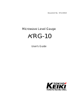
Levelmeasurementinvessels
For level measurement in vessels with conical bottom it can be advanta-
geous to mount the sensor in the centre of the vessel, as measurement is
then possible down to the bottom.
Fig. 9: Level measurement in vessels with conical bottom
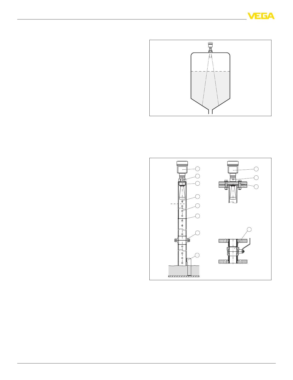
Measurement in a surge pipe
By using a surge pipe in the vessel, inuences from internal vessel
installations and turbulence can be excluded. Under these prerequisites,
the measurement of products with low dielectric values (ε
r
value ≥ 1.6) is
possible. In very adhesive products, measurement in a surge pipe is not
recommended.
0%
100%
1
2
3
1
2
3
4
5
8
6
7
9
Fig. 10: Conguration surge pipe
1 Radar sensor
2 Polarisation marking
3 Thread or ange on the instrument
4 Vent hole
5 Holes
6 Weld joint
7 Welding neck ange
8 Ball valve with complete opening
9 Fastening of the surge pipe
Flow measurement
Flow measurement in open umes with a dened constriction, such as e.g.
a rectangular overow, can be realized with a level measurement.
7
Instruments and applications
Radar
29019-US-180913
h
max
≥ 2 x h
max
90°
4
3 ... 4 h
max
90°
2 3
1
Fig. 11: Flow measurement with rectangular overow: d
min.
minimum distance of the
sensor; h
max.
= max. lling of the rectangular overow
1 Overow orice (side view)
2 Headwater
3 Tailwater
4 Overfall orice (view from tailwater)
Measurementindicultapplications
The electronics version with increased sensitivity enables use of the instru-
ment also in applications with very poor reective properties and products
with low ε
r
value.
8
Selection criteria
Radar
29019-US-180913
4 Selection criteria
VEGAPULS
WL61 61 62 63 64 65 66
Vessel Small vessels
Storage tanks
Process vessels
Process Simple process conditions
Extremely dicult process conditions
Aggressive liquids
Bubble or foam generation
Wave movements at the surface
Steam or condensation
Buildup
Flow measurement
Installation Front ush installation
Threaded ttings
Flange connections
Hygienic ttings
Mounting strap
Antenna Antenna extension
Standpipe antenna
Narrow transmission lobe
Measurement in a bypass tube or surge pipe
Rinsing air connection
Suitabilityforindustry-specic
applications
Chemical
Power generation
Foodstus
Metal production
Oshore
Paper
Petrochemical
Pharmaceutical
Shipbuilding
Environment and recycling industry
Water, waste water
Cement industry
9
Measuring range dimensioning
Radar
29019-US-180913
5 Measuring range dimensioning
Vessel
Applications Storage tank Storage tank with product circulation Stirrer vessel
VEGAPULS62 DN 50 (antenna ø
48 mm)
DN 80 (antenna ø
75 mm)
DN 100 (antenna ø
95 mm)
DN 50 (antenna ø
48 mm)
DN 80 (antenna ø
75 mm)
DN 100 (antenna ø
95 mm)
DN 50 (antenna ø
48 mm)
DN 80 (antenna ø
75 mm)
DN 100 (antenna ø
95 mm)
VEGAPULS63 DN 50 DN 80, DN 100 DN 50 DN 80, DN 100 DN 50 DN 80, DN 100
Dielectric constant <3 up to 20 m (65.62 ft) up to 35 m (114.83 ft) up to 20 m (65.62 ft) up to 35 m (114.83 ft) up to 10 m (32.81 ft) up to 20 m (65.62 ft)
Dielectric constant 3 … 10 up to 20 m (65.62 ft) up to 35 m (114.83 ft) up to 20 m (65.62 ft) up to 35 m (114.83 ft) up to 10 m (32.81 ft) up to 20 m (65.62 ft)
Dielectric constant >10 up to 20 m (65.62 ft) up to 35 m (114.83 ft) up to 20 m (65.62 ft) up to 35 m (114.83 ft) up to 20 m (65.62 ft) up to 35 m (114.83 ft)
Measurementtubes
Applications Surge pipe Bypass
VEGAPULS62 DN 50 (antenna ø
48 mm)
DN 80 (antenna ø
75 mm)
DN 100 (antenna ø
95 mm)
DN 50 (antenna ø
48 mm)
DN 80 (antenna ø
75 mm)
DN 100 (antenna ø
95 mm)
1)
VEGAPULS63 DN 50 DN 80, DN 100 DN 50 DN 80, DN 100
Dielectric constant <3 up to 30 m (98.43 ft) up to 35 m (114.83 ft) up to 30 m (98.43 ft) up to 35 m (114.83 ft)
Dielectric constant 3 … 10 up to 30 m (98.43 ft) up to 35 m (114.83 ft) up to 30 m (98.43 ft) up to 35 m (114.83 ft)
Dielectric constant >10 up to 30 m (98.43 ft) up to 35 m (114.83 ft) up to 30 m (98.43 ft) up to 35 m (114.83 ft)
1)
Free radiating radar possible, however, guided radar is recommended as there is less inuence from bypass openings.
10
Housing overview
Radar
29019-US-180913
6 Housing overview
Plastic PBT
Protection rating IP 66/IP 67 IP 66/IP 67
Version Single chamber Double chamber
Application area Industrial environment Industrial environment
Aluminium
Protection rating IP 66/IP 67, IP 66/IP 68 (1 bar) IP 66/IP 67, IP 66/IP 68 (1 bar)
Version Single chamber Double chamber
Application area Industrial environment with increased me-
chanical stress
Industrial environment with increased me-
chanical stress
Stainlesssteel316L
Protection rating IP 66/IP 67 IP 66/IP 67, IP 66/IP 68 (1 bar) IP 66/IP 67, IP 66/IP 68 (1 bar)
Version Single chamber, electropolished Single chamber, precision casting Double chamber, precision casting
Application area Aggressive environment, food processing,
pharmaceutical
Aggressive environment, extreme mechan-
ical stress
Aggressive environment, extreme mechan-
ical stress
11
Mounting
Radar
29019-US-180913
7 Mounting
Installation position
The sensor is mounted in a position which is at least 200 mm (7.874 in)
away from the vessel wall. If the sensor is installed in the center of dished
or round vessel tops, multiple echoes can arise. However, these can be
suppressed by an appropriate adjustment.
> 200 mm
(7.87
")
Fig. 24: Mounting of the radar sensor on round vessel tops
Mounting examples
The following illustrations show mounting examples and measurement
setups for the individual sensors.
Pump shaft
61 %
Fig. 25: Level measurement in the pump shaft with VEGAPULS WL 61
The strongly focussed measuring signal of VEGAPULS WL 61 oers
considerable advantages particularly in tight spaces. The sensor operates
reliably even with foam and buildup on the shaft wall.
Acid tank
Fig. 26: Level measurement in an acid tank with VEGAPULS 61
A non-contact measuring principle is particularly suitable for level measure-
ment in acid tanks.
VEGAPULS 61 is characterised by a small process tting and a PVDF
encapsulated antenna. The sensor is insensitive to temperature uctuations
and gas phases.
Reactor
Fig. 27: Level measurement in a reactor with VEGAPULS 62
For the production of resins, dierent basic substances are mixed with
solvents and a reaction is caused by adding process heat.
Non-contact measurement with the radar sensor VEGAPULS 62 is ideal
for use in the production of reaction products. Since the measurement is
performed without direct contact to the medium, virtually no buildup forms
on the sensor.
12
Mounting
Radar
29019-US-180913
Sugar evaporator
Fig. 28: Level measurement in a sugar evaporator with VEGAPULS 63
The VEGAPULS 63 radar sensor is particularly suitable for level measure-
ment in the sugar evaporator.
The PTFE encapsulated horn antenna is protected against contamination
or adhesion by the juice. The instrument is gauge and low pressure resis-
tant, even with dynamic pressure and suctions.
Process vessels
Fig. 29: Level measurement in a small process vessel with VEGAPULS 64
The strongly focussed measuring signal of VEGAPULS 64 oers consider-
able advantages particularly in small process vessels in the food process-
ing industry. The sensor operates reliably even with frequently changing
lling and emptying processes.
Storage tank
Fig. 30: Level measurement in a storage tank with VEGAPULS 65
The VEGAPULS 65 radar sensor is particularly suitable for level measure-
ment in a storage tank.
Storage tower
Fig. 31: Level measurement in a storage tower with VEGAPULS 65
The VEGAPULS 66 radar sensor is particularly suitable for level measure-
ment in a storage tower for paper suspension.
With the large anntenna and the low frequency measuring system, the
sensor functions even in case of steam and uctuating surface.
13
Electronics - 4 … 20 mA/HART - two-wire
Radar
29019-US-180913
8 Electronics - 4 … 20 mA/HART - two-wire
Congurationoftheelectronics
The plug-in electronics is mounted in the electronics compartment of the
instrument and can be exchanged by the user when servicing is required.
The electronics is completely encapsulated to protect against vibration and
moisture.
The terminals for voltage supply as well as the contact pins with I²C
interface for parameter adjustment are located on the upper side of the
electronics. In the double-chamber housing, the terminals are located in the
separate terminal compartment.
Voltage supply
Power supply and current signal are carried on the same two-wire cable.
The operating voltage can dier depending on the instrument version.
You can nd the data of the voltage supply in chapter "Technical data" in the
operating instructions manual of the respective instrument.
Provide a reliable separation between the supply circuit and the mains
circuits according to DIN EN 61140 VDE 0140-1.
Specications of the voltage supply:
Operating voltage
9.6 … 35 V DC
12 … 35 V DC
Permissible residual ripple - Non-Ex, Ex-ia instrument
for 9.6 V< U
N
< 14 V: ≤ 0.7 V
e
(16 … 400 Hz)
for 18 V< U
N
< 35 V: ≤ 1.0 V
e
(16 … 400 Hz)
Keep in mind the following additional factors that inuence the operating
voltage:
Lower output voltage of the power supply unit under nominal load (e.g.
with a sensor current of 20.5 mA or 22 mA in case of fault)
Inuence of additional instruments in the circuit (see load values in
chapter "Technical data" of the operating instructions of the respective
instrument)
Connectioncable
The instrument is connected with standard two-wire cable without screen. If
electromagnetic interference is expected which is above the test values of
EN 61326-1 for industrial areas, screened cable should be used.
We generally recommend the use of screened cable for HART multidrop
mode.
Cablescreeningandgrounding
If screened cable is required, we recommend connecting the cable screen
on both ends to ground potential. In the sensor, the screen must be
connected directly to the internal ground terminal. The ground terminal on
the outside of the housing must be connected to the ground potential (low
impedance).
Connection
Singlechamberhousing
5
1
2
+
( )
(-)
678
4...20mA
2
3
4
1
Fig. 32: Electronics and connection compartment, single chamber housing
1 Voltage supply/Signal output
2 For display and adjustment module or interface adapter
3 For external display and adjustment unit
4 Ground terminal for connection of the cable screen
Doublechamberhousing
4...20mA
2
3
1
2
+
( )
(-)
1
Fig. 33: Connection compartment, double chamber housing
1 Voltage supply/Signal output
2 For display and adjustment module or interface adapter
3 Ground terminal for connection of the cable screen
WireassignmentconnectioncableVEGAPULSWL61
1
2
Fig. 34: Wire assignment in permanently connected connection cable
1 Brown (+) and blue (-) to power supply or to the processing system
2 Shielding
14
Electronics - 4 … 20 mA/HART - four-wire
Radar
29019-US-180913
9 Electronics - 4 … 20 mA/HART - four-wire
Congurationoftheelectronics
The plug-in electronics is mounted in the electronics compartment of the
instrument and can be exchanged by the user when servicing is required.
The electronics is completely encapsulated to protect against vibration and
moisture.
The contact pins with I²C interface for parameter adjustment are located
on the upper side of the electronics. The terminals for the power supply are
located in the separate connection compartment.
Voltage supply
If a reliable separation is required, the power supply and the current output
are transmitted over separate two-wire connection cables.
Operating voltage with version for low voltage
9.6 … 48 V DC, 20 … 42 V AC, 50/60 Hz
Operating voltage with version for mains voltage
90 … 253 V AC, 50/60 Hz
Connectioncable
The 4 … 20 mA current output is connected with standard two-wire cable
without screen. If electromagnetic interference is expected which is above
the test values of EN 61326 for industrial areas, screened cable should be
used.
For voltage supply, an approved installation cable with PE conductor is
required.
Cablescreeningandgrounding
If screened cable is required, we recommend connecting the cable screen
on both ends to ground potential. In the sensor, the screen must be
connected directly to the internal ground terminal. The ground terminal on
the outside of the housing must be connected to the ground potential (low
impedance).
Connection,doublechamberhousing
power supply
4...20mA
active
passive
common
IS GND
5
1
/L
/N
PE
2
+
( )
(-)
67 8
Fig. 35: Connection compartment, double chamber housing
1 Voltage supply
2 4 … 20 mA signal output active
3 4 … 20 mA signal output passive
Terminal Function Polarity
1 Voltage supply +/L
2 Voltage supply -/N
5 4 … 20 mA output (active) +
6 4 … 20 mA output (passive) +
7 Mass - output -
8 Functional ground with installa-
tion according to CSA
15
Electronics - Probus PA
Radar
29019-US-180913
10 Electronics-ProbusPA
Congurationoftheelectronics
The plug-in electronics is mounted in the electronics compartment of the
instrument and can be exchanged by the user when servicing is required.
The electronics is completely encapsulated to protect against vibration and
moisture.
The terminals for voltage supply as well as the plug with I²C interface for
parameter adjustment are located on the upper side of the electronics. In
the double-chamber housing, these connection elements are located in the
separate connection compartment.
Voltage supply
The voltage supply is provided by a Probus DP /PA segment coupler.
Specications of the voltage supply:
Operating voltage
9 … 32 V DC
Max. number of sensors per DP/PA segment coupler
32
Connectioncable
Connection is carried out with screened cable according to Probus spec-
ication.
Make sure that the entire installation is carried out according to the Probus
specication. In particular, make sure that the bus is terminated with suit-
able terminating resistors.
Cablescreeningandgrounding
In systems with potential equalisation, connect the cable screen directly to
ground potential at the power supply unit, in the connection box and at the
sensor. The screen in the sensor must be connected directly to the internal
ground terminal. The ground terminal outside on the housing must be con-
nected to the potential equalisation (low impedance).
In systems without potential equalisation, connect the cable screen directly
to ground potential on the power supply unit and the sensor. In the connec-
tion box or T-distributor, the screen of the short stub to the sensor may not
be connected to ground potential or to another cable screen.
Connection
Singlechamberhousing
5
00
5
1
6
2
7
3
8
4
9
0
5
1
6
2
7
3
8
4
9
1
0
1
678
Bus
2
3
4
5
1
2
+
( )
(-)
1
Fig. 36: Electronics and connection compartment, single chamber housing
1 Voltage supply/Signal output
2 For display and adjustment module or interface adapter
3 Selection switch for bus address
4 For external display and adjustment unit
5 Ground terminal for connection of the cable screen
Connection,doublechamberhousing
Bus
5
1
2
+
( )
(-)
678
2
3
4
1
Fig. 37: Connection compartment, double chamber housing
1 Voltage supply, signal output
2 For display and adjustment module or interface adapter
3 For external display and adjustment unit
4 Ground terminal for connection of the cable screen
WireassignmentconnectioncableVEGAPULSWL61
1
2
Fig. 38: Wire assignment in permanently connected connection cable
1 Brown (+) and blue (-) to power supply or to the processing system
2 Shielding
16
Electronics - Foundation Fieldbus
Radar
29019-US-180913
11 Electronics-FoundationFieldbus
Congurationoftheelectronics
The plug-in electronics is mounted in the electronics compartment of the
instrument and can be exchanged by the user when servicing is required.
The electronics is completely encapsulated to protect against vibration and
moisture.
The terminals for voltage supply as well as the contact pins with I²C
interface for parameter adjustment are located on the upper side of the
electronics. In the double-chamber housing, the terminals are located in the
separate terminal compartment.
Voltage supply
Power supply via the H1 Fieldbus cable.
Specications of the voltage supply:
Operating voltage
9 … 32 V DC
max. number of sensors
32
Connectioncable
Connection is carried out with screened cable according to Fieldbus spec-
ication.
Make sure that the entire installation is carried out according to the Fieldbus
specication. In particular, make sure that the bus is terminated with suit-
able terminating resistors.
Cablescreeningandgrounding
In systems with potential equalisation, connect the cable screen directly to
ground potential at the power supply unit, in the connection box and at the
sensor. The screen in the sensor must be connected directly to the internal
ground terminal. The ground terminal outside on the housing must be con-
nected to the potential equalisation (low impedance).
In systems without potential equalisation, connect the cable screen directly
to ground potential on the power supply unit and the sensor. In the connec-
tion box or T-distributor, the screen of the short stub to the sensor may not
be connected to ground potential or to another cable screen.
Connection
Singlechamberhousing
1
2
( )
(-)
1
5
0
1
0
1
+
678
Bus
2
3
4
5
Fig. 39: Electronics and connection compartment, single chamber housing
1 Voltage supply/Signal output
2 Contact pins for the display and adjustment module or interface adapter
3 Selection switch for bus address
4 For external display and adjustment unit
5 Ground terminal for connection of the cable screen
Connection,doublechamberhousing
Bus
5
1
2
+
( )
(-)
678
2
3
4
1
Fig. 40: Connection compartment, double chamber housing
1 Voltage supply, signal output
2 For display and adjustment module or interface adapter
3 For external display and adjustment unit
4 Ground terminal for connection of the cable screen
WireassignmentconnectioncableVEGAPULSWL61
1
2
Fig. 41: Wire assignment in permanently connected connection cable
1 Brown (+) and blue (-) to power supply or to the processing system
2 Shielding
17
Electronics - Modbus, Levelmaster protocol
Radar
29019-US-180913
12 Electronics-Modbus,Levelmasterprotocol
Congurationoftheelectronics
The plug-in electronics is mounted in the electronics compartment of the
instrument and can be exchanged by the user when servicing is required.
The electronics is completely encapsulated to protect against vibration and
moisture.
The contact pins with I²C interface for parameter adjustment are located
on the upper side of the electronics. The terminals for the power supply are
located in the separate connection compartment.
Voltage supply
Power supply via the Modbus host (RTU)
Operating voltage
8 … 30 V DC
max. number of sensors
32
Connectioncable
The instrument is connected with standard two-wire, twisted cable suitable
for RS 485. If electromagnetic interference is expected which is above the
test values of EN 61326 for industrial areas, screened cable should be
used.
For power supply, a separate two-wire cable is required.
Make sure that the entire installation is carried out according to the Fieldbus
specication. In particular, make sure that the bus is terminated with suit-
able terminating resistors.
Cablescreeningandgrounding
In systems with potential equalisation, connect the cable screen directly to
ground potential at the power supply unit, in the connection box and at the
sensor. The screen in the sensor must be connected directly to the internal
ground terminal. The ground terminal outside on the housing must be con-
nected to the potential equalisation (low impedance).
In systems without potential equalisation, connect the cable screen directly
to ground potential on the power supply unit and the sensor. In the connec-
tion box or T-distributor, the screen of the short stub to the sensor may not
be connected to ground potential or to another cable screen.
Connection
Doublechamberhousing
+
+
power supply
MODBUS
D0
D1
IS GND
USB
1
2
4 3
1345
2off
on
( )
(
)
(-)
(-)
Fig. 42: Connection compartment
1 USB interface
2 Slide switch for integrated termination resistor (120 Ω)
3 Modbus signal
4 Voltage supply
18
Adjustment
Radar
29019-US-180913
13 Adjustment
13.1 Adjustment directly at the measuring point
Via the display and adjustment module through keys
The plug-in display and adjustment module is used for measured value
indication, adjustment and diagnosis. It is equipped with an illuminated full
dot matrix as well as four keys for adjustment.
Fig. 43: Display and adjustment module with single chamber housing
Via the display and adjustment module through magnetic pen
With the Bluetooth version of the display and adjustment module, the sen-
sor can also be adjusted with the magnetic pen. This is done right through
the closed lid (with inspection window) of the sensor housing.
Fig. 44: Display and adjustment module - with adjustment via magnetic pen
Via a PC with PACTware/DTM
The interface converter VEGACONNECT is required for connection of the
PC. The converter is placed on the sensor instead of the display and adjust-
ment module and connected to the USB interface of the PC.
2
3
1
4
Fig. 45: Connection of the PC via VEGACONNECT and USB
1 VEGACONNECT
2 Sensor
3 USB cable to the PC
4 PC with PACTware/DTM
PACTware is an adjustment software for conguration, parameter adjust-
ment, documentation and diagnosis of eld devices. The corresponding
device drivers are called DTMs.
13.2 Operation in the measurement loop environment
- wireless via Bluetooth
Viaasmartphone/tablet
The display and adjustment module with integrated Bluetooth functionality
allows wireless connection to smartphones/tablets with iOS or Android op-
erating system. The adjustment is carried out via the VEGA Tools app from
the Apple App Store or Google Play Store.
1
2
3
Fig. 46: Wireless connection to smartphones/tables
1 Display and adjustment module
2 Sensor
3 Smartphone/Tablet
Via a PC with PACTware/DTM
The wireless connection from the PC to the sensor is carried out via the
Bluetooth USB adapter and a display and adjustment module with inte-
grated Bluetooth function. The adjustment is carried out via the PC with
PACtware/DTM.
2
1
4
3
Fig. 47: Connection of the PC via Bluetooth USB adapter
1 Display and adjustment module
2 Sensor
3 Bluetooth USB adapter
4 PC with PACTware/DTM
13.3 Adjustment carried out at position remote from
the measuring point - wired
Via external display and adjustment units
For this, the external display and adjustment units VEGADIS 81 and 82 are
available. The adjustment is carried out via the keys of the built-in display
and adjustment module.
The VEGADIS 81 is mounted at a distance of 50 m from the sensor and
directly to the sensor electronics. VEGADIS 82 is looped directly into the
signal cable at any point.
19
Adjustment
Radar
29019-US-180913
4
1
3
2
5
4
Fig. 48: Connection of VEGADIS 81 to the sensor
1 Voltage supply/Signal output sensor
2 Sensor
3 Connection cable sensor - external display and adjustment unit
4 External display and adjustment unit
5 Display and adjustment module
4
5
3
1
2
Fig. 49: Connection of VEGADIS 82 to the sensor
1 Voltage supply/Signal output sensor
2 External display and adjustment unit
3 Display and adjustment module
4 4 … 20 mA/HART signal cable
5 Sensor
Via a PC with PACTware/DTM
The sensor adjustment is carried out via a PC with PACTware/DTM.
4
5
6
3
2
1
Fig. 50: Connection of VEGADIS 82 to the sensor, adjustment via PC with PACTware
1 Voltage supply/Signal output sensor
2 External display and adjustment unit
3 VEGACONNECT
4 4 … 20 mA/HART signal cable
5 Sensor
6 PC with PACTware/DTM
13.4 Adjustment carried out at position remote from
themeasuringpoint-wirelessthroughmobile
network
As an option, the radio module PLICSMOBILE can be mounted into a plics
®
sensor with double chamber housing. It is used for transmission of mea-
sured values and for remote parameter adjustment of the sensor.
Fig. 51: Transmission of measured values and remote parameter adjustment of the
sensor via mobile phone network.
13.5 Alternative adjustment programs
DD adjustment programs
Device descriptions as Enhanced Device Description (EDD) are available
for DD adjustment programs such as, for example, AMS™ and PDM.
The les can be downloaded at www.vega.com/downloads under "Soft-
ware".
FieldCommunicator375,475
Device descriptions for the instruments are available as EDD for parameter-
isation with Field Communicator 375 or 475.
Integrating the EDD into the Field Communicator 375 or 475 requires the
"Easy Upgrade Utility" software, which is available from the manufacturer.
This software is updated via the Internet and new EDDs are automatically
accepted into the device catalogue of this software after they are released
by the manufacturer. They can then be transferred to a Field Communicator.
20
Dimensions
Radar
29019-US-180913
14 Dimensions
Plastic housing
~ 69 mm
(2.72")
ø 79 mm
(3.11")
112 mm
(4.41")
M20x1,5/
½ NPT
~ 84 mm
(3.31")
M16x1,5
112 mm
(4.41")
M20x1,5/
½ NPT
1
2
ø 79 mm
(3.11")
1 Single chamber housing
2 Double chamber housing
Aluminium housing
21
ø 86 mm
(3.39")
~ 116 mm
(4.57")
116 mm
(4.57")
M20x1,5
M20x1,5/
½ NPT
~ 87 mm
(3.43")
M16x1,5
ø 86 mm
(3.39")
120 mm
(4.72")
M20x1,5/
½ NPT
1 Single chamber housing
2 Double chamber housing
Stainless steel housing
~ 69 mm
(2.72")
ø 79 mm
(3.11")
117 mm
(4.61")
M20x1,5/
½ NPT
~ 59 mm
(2.32")
ø 80 mm
(3.15")
112 mm
(4.41")
M20x1,5/
½ NPT
~ 87 mm
(3.43")
ø 86 mm
(3.39")
120 mm
(4.72")
M20x1,5/
½ NPT
M16x1,5
321
1 Single chamber housing, electropolished
2 Single chamber housing, precision casting
2 Double chamber housing, precision casting
VEGAPULSWL61
2
1
15 mm
(0.59")
98 mm
(3.86")
300 mm
(11.81")
42,5 mm
(1.67")
ø 75 mm
(2.95")
170 mm / 300 mm
(6.69" / 11.81")
ø 72 mm
(2.84")
G1 1/2
ø 115 mm
(4.53")
Fig. 55: Dimensions VEGAPULS
1 Mounting strap
2 Combi compression ange
VEGAPULS61
2
4
3
1
43 mm
(1.69")
20 mm
(0.79")
78 mm
(3.07")
ø 39 mm
(1.54")
SW 50 mm
(1.97")
G1½ A
15 mm
(0.59")
98 mm
(3.86")
170 mm / 300 mm
(6.69" / 11.81")
19 mm
(0.75")
ø 75 mm
(2.95")
ø 115 mm
(4.53")
1 Version with encapsulated antenna system (ø 40 mm)
2 Version with plastic horn antenna (ø 80 mm)
3 Mounting strap
4 Adapter ange
  • Page 1 1
  • Page 2 2
  • Page 3 3
  • Page 4 4
  • Page 5 5
  • Page 6 6
  • Page 7 7
  • Page 8 8
  • Page 9 9
  • Page 10 10
  • Page 11 11
  • Page 12 12
  • Page 13 13
  • Page 14 14
  • Page 15 15
  • Page 16 16
  • Page 17 17
  • Page 18 18
  • Page 19 19
  • Page 20 20
  • Page 21 21
  • Page 22 22
  • Page 23 23
  • Page 24 24

Vega VEGAPULS 66 Product information

Type
Product information

Ask a question and I''ll find the answer in the document

Finding information in a document is now easier with AI