Oregon Scientific EMR812A User manual
- Category
- Weather stations
- Type
- User manual
This manual is also suitable for

1
GB
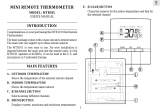
MULTI-CHANNEL IN-OUT
CABLE FREE THERMOMETER
MODEL: EMR812
USER’S MANUAL
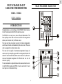
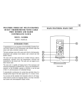
INTRODUCTION
Congratulations on your purchase of the EMR812 Multi-Channel
In-Out Thermometer with 433MHz cable free sensor.
The EMR812 is an easy-to-use, state-of-the-art thermometer. The
basic package comes with a main unit, which is the temperature
station, and a remote unit, the thermo sensor.
The main unit has extra-large read-outs for indoors temperature
and for that collected and transmitted by the remote unit. The main
unit can support up to three remote units.
The main unit is capable of monitoring temperature changes of
remote sites. By setting the upper and lower temperature limits the
alarm will activate when those limits are exceeded. Also, the maxi-
mum and minimum temperature of different sites can also be
retrieved quickly.
No wire installation is required between the main and remote units.
As the EMR812 operates at 433MHz, it can be used in the U.S. and
most places in Continental Europe.
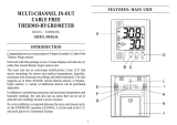
MAIN FEATURES: MAIN UNIT
HI ON/OFF
RESET
TEMP AL
°C
°FLO
CHANNEL MEM
CLEAR
433MHz CABLE FREE

2
GB
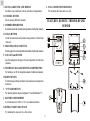
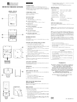
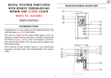
L WALL - MOUNT RECESSED HOLE
For mounting the main unit on a wall
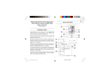
FEATURES: REMOTE THERMO-HYGRO
SENSOR
A EXTRA LARGE TWO - LINE DISPLAY
Facilitates easy reading of remote and indoors temperatures
B CHANNEL BUTTON
Selects among different channels
C MEMORY (MEM) BUTTON
Recalls the maximum or minimum temperature of individual channels
D CLEAR BUTTON
Clears the maximum and minimum temperatures of individual
channels
E HIGH (HI) / LOW (LO) BUTTON
Sets the upper or lower temperature alarm limits of individual channels
F ADVANCE (s ) BUTTON
Sets the readings for the upper or lower temperature of individual
channels
G TEMPERATURE ALARM (TEMP AL) ON/OFF BUTTON
For turning on or off, the temperature alarm of individual channels
H RESET BUTTON
For returning all settings to default values and erases temperature
memories
I °C/°F SLIDE SWITCH
For selecting between degree Centigrade (°C) and Fahrenheit (°F)
J BATTERY COMPARTMENT
Accommodates two UM3 or "AA" size alkaline batteries
K RETRACTABLE TABLE STAND
For standing the main unit on a flat surface

3
GB
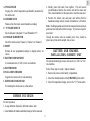
A. TWO-LINE LCD
Displays the current temperature and humidity monitored by
the remote unit
B. LED INDICATOR
Flashes when the remote sensor transmits a reading
C. °C/°F SLIDE SWITCH
Selects between Centigrade (°C) and Fahrenheit (°F)
D. CHANNEL SLIDE SWITCH
Select the remote sensor Channel 1, Channel 2 or Channel 3
E. RESET
Returns all user programmed settings to original factory set
values
F. BATTERY COMPARTMENT
Accommodates two (2) UM-3 or AA-size batteries
G. BATTERY DOOR
H. WALL-MOUNT HOLDER
Supports the remote unit in wall-mounting
I. REMOVABLE TABLE STAND
For standing the remote unit on a flat surface
BEFORE YOU BEGIN
For best operation,
1. Assign different channels to different remote units.
2. Insert batteries for remote units before doing so for the main unit.
3. Initially place both units close together. This will ensure
synchronization between the remote unit and the main unit.
Then, install batteries for the main unit or reset the main unit.
4. Position the remote unit and main unit within effective
transmission range, which, in usual circumstances, is 30 meters.
Note : Building materials and where the main and remote units are
positioned can vastly affect effective range. Try various set-ups for
best result.
Though the remote units are weather proof, they should be
placed away from direct sunlight, rain or snow.
BATTERY AND CHANNEL
INSTALLATION: REMOTE UNIT
The remote thermo-hygro sensor unit uses two (2) UM-3 or “AA”
size batteries.
Follow these steps to install / replace batteries:
1. Remove the screws on the battery compartment.
2. Select the channel number on the [CHANNEL] slide switch.
3. Select the temperature display unit on the °C/°F slide switch.

4
GB
4. Insert the batteries strictly according to the polarities shown therein.
5. Replace the battery compartment door and secure its screws.
Replace the batteries when the low-battery indicator of the particular
channel lights up on the main unit. (Repeat the steps described in
section “BEFORE YOU BEGIN”)
Note that once a channel is assigned to a remote unit, you can only
change it by removing the batteries or resetting the unit.
BATTERY INSTALLATION: MAIN UNIT
The main unit uses two UM3 or "AA" size alkaline batteries.
To install them,
1. Slide open the battery compartment door.
2. Insert the batteries strictly according to the polarities shown therein.
3. Replace the battery compartment door.
LOW BATTERY WARNING
Replace the batteries when the low-battery indicator of the indoor
temperature display lights up. (Repeat the steps described in
section "BEFORE YOU BEGIN")
Respectively, for a remote sensor unit, the low-battery icon will
show when the channel is selected.
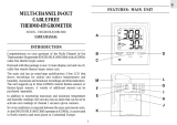
GETTING STARTED
Once batteries are in place for the remote units, they will start
transmitting temperature readings at 30-second intervals.
The main unit will also start searching for signals for about a
minute once batteries are installed. Upon successful reception, the
individual channel temperatures will be displayed on the top line
and the indoors temperature on the bottom line. The main unit will
automatically update its readings at about 30-second intervals.

5
GB
If no signals are received, blanks “ ” will be displayed and
the kinetic wave icon will show “
”. Press CHANNEL and MEM
simultaneously to enforce another search for about 30 seconds.
This is useful in synchronizing the transmission and reception of
the remote and main units.
Repeat this step whenever you find discrepancies between the
reading shown on the main unit and that on the respective remote
unit.
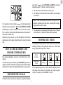
HOW TO CHECK REMOTE AND
INDOORS TEMPERATURES
The indoors temperature is shown on the bottom line of the
display.
As for the remote sites or channels, press CHANNEL to go from one
channel to another. The kinetic wave display on the channel number
indicates the reception of that particular channel is in good order.
DISCONNECTED SIGNALS
If without obvious resasons the display for a particular channel
goes blank “ ”, press CHANNEL and MEM to enforce an
immediate search. If this fails, check the following.
1. The remote unit of that channel is still in place.
2. The batteries of both the remote unit and main unit and replace
as necessary.
Note : When the temperature falls befow freezing point, the
batteries of outdoor units will freeze, lowering their voltage
supply and the effective range.
3. The transmission is within range and the path is clear of obstacles
and interference. Shorten the distance when necessary.
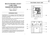
TEMPERATURE TREND
The temperature trend indicator on the screen shows the trend of
readings collected at that particular remote site. Three trends,
rising, steady and falling, will be shown.
If the temperature goes above or below than the temperature meas-
uring range of the main unit or the remote unit ( stated in specifi-
cation), the display will show “HHH” or “LLL”.
Arrow
indicator
Temperature
Trend
Steady FallingRising

6
GB
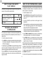
HOW TO USE TEMPERATURE ALARMS
The temperature alarms allow you to set the upper and lower limits
of readings for individual channels. The alarm will activate if a
limit is exceeded. To set the alarm,
1. Select the channel to be set.
2. Press the HI/LO button for the upper (HI) or lower (LO) limit. An
“OFF” message will be displayed if the alarm for that limit is
turned off.
3. Use the ADVANCE ( s ) button to set the upper or lower
temperature.
If this is the first time you set the limits, the lower limit will start from
-50°C (-58°F) and the upper limit +70°C (158°F). Otherwise, the
reading will start from the temperature last selected.
Each press on the button will increase the temperature by one degree.
Holding on the button will step up the increment by five.
4. Press TEMP AL ON/OFF button to switch on or off the Max./
Min. temperature alarm. The set limit will be displayed.
5. Press HI/LO button to set another limit or return to normal
display. The respective HI, LO or both indicators will light up to
signify the status of the alarm.
When an alarm activates, the display will switch to the respective
channel with the display flashing. If undisturbed, it will alarm for
one minute. Press any key to momentarily mute the alarm. It will
alarm again if the temperature continues to exceed the set limit.
To disable an alarm altogether, select the channel and use TEMP
AL ON/OFF to turn it off.
If you have set the upper and lower temperatures for more than one
HOW TO READ THE KINETIC
WAVE DISPLAY
The kinetic wave display shows the signal receiving status of the
main unit. There are three possible forms:
MAXIMUM AND MINIMUM
TEMPERATURES
The maximum and minimum recorded indoor temperatures and
those of each channel will be automatically stored in memory. To
display them,
1. Select the channel to be checked.
2. Press MEM once to display the maximum temperature and again
the minimum temperature. The respective indicators, MAX or
MIN will be displayed.
To clear the memory, press CLEAR. All segments of the display will light
up for two seconds. The display will return to the last screen with
maximum and minimum temperature erased from memory.
If you press MEM now, the maximum and minimum temperatures
will have the same values as the current ones until different read-
ings are recorded.
The unit is in searching mode.
Temperature readings are
securely registered.
No signals.

7
GB
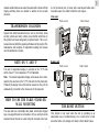
As for the remote unit, it comes with a wall-mount holder and a
removable stand. Use either to hold the unit in place.
THE RESET BUTTON
This button is only used when the unit is operating in an
unfavorable way or malfunctioning. Use a blunt stylus to hold
down the button. All settings will return to their default values.
channel and the limits are exceeded, the alarm will activate with the
display switching from one channel to another at five seconds
intervals.
TRANSMISSION COLLISION
Signals from other household devices, such as door bells, home
security systems and entry controls, may interfere with those of
this product and cause temporarily reception failure. This is nor-
mal and does not affect the general performance of the product. The
transmission and reception of temperature readings will resume
once the interference recedes.
NOTE ON °C AND °F
The unit of temperature display is selected on the °C/°F slide
switch. Select °C for Centigrade or °F for Fahrenheit.
Note : The remote temperature display on the main unit is domi-
nated by the selection on the °C/°F slide switch of the main unit.
Whatever the display units of the remote sensors are, they will be
automatically converted to the chosen one of the main unit.
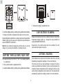
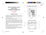
HOW TO USE THE TABLE STAND OR
WALL MOUNTING
The main unit has a retractable table stand, which when flipped
open, can support the unit on a flat surface. Or you can flip close the
stand and mount the unit on a wall using the recessed screw hole.
Remote unit
Wall-mount Table Stand
Main unit
Wall-mount Table Stand

8
GB
PRECAUTIONS
This product is engineered to give you years of satisfactory service
if you handle it carefully. Here are a few precautions:
1. Do not immerse the unit in water.
2. Do not clean the unit with abrasive or corrosive materials. They
may scratch the plastic parts and corrode the electronic circuit.
3. Do not subject the unit to excessive force, shock, dust,
temperature or humidity, which may result in malfunction,
shorter electronic life span, damaged battery and distorted parts.
4. Do not tamper with the unit’s internal components. Doing so
will invalidate the warranty on the unit and may cause
unnecessary damage. The unit contains no user-serviceable
parts.
5. Only use fresh batteries as specified in the user’s manual. Do not
mix new and old batteries as the old ones may leak.
6. Always read the user’s manual thoroughly before operating the
unit.
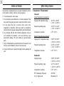
SPECIFICATIONS
Temperature Measurement
Main unit
Indoor Temperature measurement
Displayed IN temperature range : 14.2°F to 158.0°F
(-9.9°C to +70.0°C)
Proposed operating range : 23.0°F to 122.0°F
(-5.0°C to +50.0°C )
Temperature resolution : 0.2°F (0.1°C)
Remote Temperature measurement
Displayed OUT temperature range : -58.0°F to 158.0°F
(-50.0°C to +70.0°C)
Proposed operating range : 23.0°F to 122.0°F
(-5.0°C to +50.0°C)
Temperature resolution : 0.2°F (0.1°C)
Remote unit
Displayed range : -58.0°F to 158.0°F
(-50.0°C to +70.0°C)
Proposed operating range : -4.0°F to 140.0°F
(-20.0°C to +60.0°C)
Temperature resolution : 0.2°F (0.1°C)
RF Transmission Frequency : 433 MHz
No. of Remote unit : Maximum of 3

9
GB
Warning: Changes or modifications to this unit not expressly
approved by the party responsible for compliance could void the
user’s authority to operate the equipment.
FCC :
NOTE: This equipment has been tested and found to comply with the
limits for a Class B digital device, pursuant to Part 15 of the FCC Rules.
These limits are designed to provide reasonable protection against
harmful interference in a residential installation. This equipment generates,
uses and can radiate radio frequency energy and, if not installed and used
in accordance with the instructions, may cause harmful interference to
radio communications.
However, there is no guarantee that interference will not occur in a
particular installation. If this equipment does cause harmful
interference to radio or television reception, which can be determined
by turning the equipment off and on, the user is encouraged to try
to correct the interference by one or more of the following measures:
o Reorient or relocate the receiving antenna.
o Increase the separation between the equipment and receiver.
o Connect the equipment into an outlet on a circuit different from
that to which the receiver is connected.
o Consult the dealer of an experienced radio/TV technician for help.
Company Name: Oregon Scientific, Inc.
Address: 19861 SW 95th Place, Tualatin, Oregon 97062, USA
Telephone Number: (1)503-6398883
Name and model number of the product: Digital Weather Forecaster
with Remote Thermo-Hygro sensor and Radio Controlled Clock
BAR112HGA
RF Transmission Range : Maximum 100 feet
(30 meters)
Temperature sensing cycle : around 30 seconds
Power
Main unit : use 2 pcs UM-3 or “AA”
1.5V alkaline battery
Remote sensing unit : use 2 pcs UM-4 or
“AAA” 1.5V alkaline
battery
Weight
Main unit : 8.82 ounces (250 g)
(without batteries)
Remote sensing unit : 3.51ounces(100g)
(without batteries)
Dimension
Main unit : 4.61x4.21x1.07inches
(117 x 107 x 26 mm)
Remote sensing unit : 3.62x2.36x.83 inches
(92 x 60 x 21 mm)
NOTE ON COMPLIANCE
This device complies with Part 15 of the FCC Rules. Operation is
subject to the following two conditions: (1) This device may not
cause harmful interference, and (2) This device must accept any
interference received, including interference that may cause
undesired operations.

CAUTION
— The content of this manual is subject to change without
further notice.
— Due to printing limitation, the displays shown in this
manual may differ from the actual display.
— The manufacturer and its suppliers held no
responsibility to you or any other person for any damage
expenses, lost profits, or any other claim arise by using
this product.
— The contents of this manual may not be reproduced
without the permission of the manufacturer.
CUSTOMER ASSISTANCE
Should you require assistance regarding this product and its
operation, please contact our customer care department at
800-853-8883 or via email at [email protected].
WARRANTY
This product is warranted to be free of manufacturing defects for
a period of 3 months from date of retail purchase. Defective
product should be directed to the place of retail purchase for
exchange. Should this not be possible, contact our customer care
department for assistance and a return material authorization. No
returns may be made without a return authorization. Please retain
your retail receipt as you may be asked to provide a copy of it
for proof of date purchased.
This warranty does not cover product subjected to abuse,
misuse, accidental damage or tampering.

MODEL: EMR812
MULTI-CHANNEL IN-OUT
CABLE FREE THERMOMETER
Instruction Manual
****
Mode D'emploi
****
Bedienungsanleitung
****
Manuale di Istruzioni
****
Instrucciones de Funcionamiento
-
 1
1
-
 2
2
-
 3
3
-
 4
4
-
 5
5
-
 6
6
-
 7
7
-
 8
8
-
 9
9
-
 10
10
-
 11
11


Oregon Scientific EMR812A User manual
- Category
- Weather stations
- Type
- User manual
- This manual is also suitable for
Ask a question and I''ll find the answer in the document
Finding information in a document is now easier with AI
Related papers
-
 Oregon Scientific EMR812HGN User manual
-
 Oregon Scientific MTR101 User manual
-
 Oregon Scientific EMR963HG User manual
-
 Oregon Scientific THN138 User manual
-
 Oregon Scientific EMR812HGN User manual
-
 Oregon Scientific EMR899HGN User manual
-
Oregon Scientific BAR888 User manual
-
 Oregon Scientific BAR888A User manual
-
 Oregon Scientific BAR182HG User manual
-
 Oregon Scientific RMR132HG User manual


Other documents
-
Home Accents Holiday NH4138 Installation guide
-
 Minder Research EMGR819LR User manual
-
Ansen Electronics L5C0668TX User manual
-
Jia Ming Toys Factory 6601 User manual
-
Traceable 4618 Owner's manual
-
General Tools EMR963HG Installation guide
-
Inter-Tech 88885125 Datasheet
-
Honeywell 2AL7Q-D1 Kinetic Door Contact User manual
-
Sharper Image OQ234 User manual
-
