Page is loading ...

1 www.observint.com ALI-NS4012R_CQ
190708
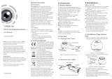
microSD card slot Reset* button
Not used
Underside of camera body
Maintenance panel cover
* To restore the camera with its default conguration (including user name, password, IP address, etc.) press and hold the Reset
button for 10 s when the camera is power on or rebooting.
Camera maintenance panel
NOTE
The microSD card may need to be initialized before it can be used to record data. Refer to the ALIBI™
IP Camera Firmware User Manual provided at AlibiSecurity.com/resources for instructions to
initialize the card.
3. Reinstall the cover.
Step 2. Mount the camera onto a wall or ceiling
For this mounting option, the drop cables can be routed through the mounting surface, or through the
cable channel in the mounting base.
Ground
terminal
Cable
channel
Mounting
screws (3)
1. Determine the best fasteners for securing the camera mounting base to mounting surface. The
mounting hardware provided may be suitable for some surfaces.
2. Using the template provided or the camera mounting base as a template, mark the locations of
the holes for the mounting screws. Also mark the location of a hole for the camera drop cables
if needed.
3. Drill holes into the mounting surface as needed.
4. Route extension cables from the power source and LAN switch (or LAN with PoE) to the
mounting location.
5. Connect the network LAN and power extension cables to the camera drop cables:
a. Connect the Ethernet LAN cable to the camera LAN drop cable. Protect the connection
from moisture and other contamination, if necessary. A Weatherproof Ethernet Fitting is
provided. Installation instructions for the tting are included later in this document.
Network drop cable
from camera
Network cable from
router or switch
Weatherproof Ethernet Fitting installed
WARNING
!
Failure of the power or Ethernet connector due to moisture or another
contaminant is considered an installation error, which voids the warranty. If
installing this camera in a location such as an overhang, shop, garage, kitchen,
etc. where high humidity or dust is present, seal these connections adequately.
ALI-NS4012R 2 MP IP 100 ft IR
Bullet Camera
Quick Installation Guide
This document guides you through the basic steps to install and congure the ALI-NS4012R IP bullet
camera. This camera features:
• 1/2.8” 1920 × 1080 pixel @ 30 fps Progressive Scan CMOS sensor
• 2.8 mm lens with 108° horizontal eld of view
• Color: 0.005 Lux @ (F1.2, AGC ON), 0 Lux with IR,
Color: 0.009 Lux @ (F1.6, AGC ON), 0 Lux with IR minimum illumination
• H.265+ / H.265 / H.264+ / H.264 compression
• 120 dB Wide Dynamic Range
• 3D DNR Digital Noise Reduction
• 100 ft Full Frame IR
• Supports onboard microSD/SDHC/SDXC card storage up to 128GB (card not included)
• IP67 rated, −22 °F ~ 140 °F temperature range
For more information, refer to these documents - available from your equipment vendor:
• ALIBI™ Tools Utility Installation software and User Manual
• ALIBI™ Witness App for Android Quick Start Guide
• ALIBI™ IP Camera Firmware Version 5.4 User Manual (or later) provided at:
AlibiSecurity.com/resources
Mounting base
Lock nut
Access to microSD slot and Reset button*
Lens
Camera body
Articulated
mounting
bracket
12 Vdc Power connector with plug
Ethernet connector - PoE capable
Camera drop cables
What’s in the box
Your camera includes:
• This document
• Drill template
• Security L-wrench
• Waterproof Ethernet tting
• Mounting hardware - screws and wall
inserts
Weatherproof
Ethernet Fitting
Mounting hardware
Step 1. Install a microSD card (optional)
The camera includes hardware to install it directly to a ceiling (horizontal surface) or wall (vertical
surface). To install the camera:
1. Remove the maintenance panel cover on the underside of the camera.
2. Insert a microSD card (see Specications section for card types) into the card slot. The card
should slide in smoothly. Push the card all the way in until it latches in place.

2
www.observint.com
b. If the camera is not powered using PoE (Power over Ethernet injector), connect the 12 Vdc
power cable to the camera drop cable. The polarity of the drop cable connector is shown in
the drop cable photo above.
CAUTION
Do not apply power to the camera at this time. Before applying power to the camera, ensure
that the polarity is correct. An incorrect connection may cause a malfunction and can damage
the camera.
6. Attach an earth ground cable to the ground terminal on the back of the camera body. Follow
local electrical codes when grounding the camera.
7. For outdoor installations, seal holes drilled in the mounting surface to block moisture and other
contaminants, if necessary.
8. Secure the camera to the mounting surface using appropriate fasteners.
9. Apply power to the camera through the 12 Vdc power cable or PoE injector, as congured.
Step 3. Install the Alibi Config Tool software
NOTE: If the camera LAN extension cable is attached to a Network Video Recorder (NVR), skip this step.
The Alibi Cong Tool is a PC-based network utility for discovery of Alibi compatible devices. It provides
an easy way to activate devices, congure camera and recorder network conguration settings, and set
device passwords. It can be installed on a Microsoft® Windows® operating system that has direct access
to the network where your Alibi devices are installed. You can download the Alibi Conguration Tool
from AlibiSecurity.com/Resources.
1. Download the Alibi Cong Tool from the AlibiSecurity.com/Resources website. At the time
when this document was published, the le is named: alibi-cong-tool.zip and is about 80MB.
2. Un-zip the le on a computer with Microsoft Windows (Windows 7 or newer) that is connected
to the LAN where your Alibi camera is connected.
3. Run the le contained in the zip le: Alibi Cong Tool.exe. Follow the on-screen instructions
to install the le.
4. Open the Alibi Cong Tool application. When the application opens, it automatically “discovers”
and lists all Alibi compatible devices on the LAN. See below.
NOTE
In the screen above, the tool can discover devices on other sub-nets. It will also list other Alibi
compatible devices on the LAN, and devices with the address 192.168.1.64 (an inactive Alibi device).
Step 4. Activate Inactive Alibi device
NOTE: If the camera LAN extension cable is attached to a Network Video Recorder (NVR), skip this step.
Refer to the documentation available for your NVR rmware for the procedure to activate the camera.
When an Alibi device is rst installed, or reset to its factory conguration, it must be “Activated” before
it can be used. In the Alibi Conguration Tool, “Inactive” devices have a Security status of Inactive,
and an IPv4 address of 192.168.1.64. A device is “Activated” when a password is assigned to the
admin username of the device.
In the example below, an ALI-NS4012R camera is activated and congured for its network. The
procedure is similar for all other Alibi network cameras currently available.
1. Peruse the list of devices the Alibi Cong Tool discovered for the Inactive device you want to
activate (see below). Click on the device in the list to highlight it, and then click the select box to
check it.
ActivateSelected
2. Click the Activate button. In the Activate window, you will create a password for the admin
(administrator) username.
a. In the Activate window, enter an a password for admin in the New Password eld.
Include a combination of uppercase, lowercase alphabetic characters and numbers to
create a “Strong” password. The rating is shown beneath the Password eld. See above.
b. Enter the admin password again in the Conrm eld, and then click Activate. In the
screen below, notice that the device Security status shows “Active”. Record your admin
password for reference later.
CAUTION
If you lose your admin (administrator) password, you cannot congure the device or restore
it to its factory settings. To reset your password, call your support organization for specic
instructions.
Notice that although the device is now activated, it retained the default IP address.
Step 5. Edit Network Parameters
NOTE: If the camera LAN extension cable is attached to a Network Video Recorder (NVR), skip this
step. The camera will receive network conguration settings from the NVR. Refer to the documentation
available for your NVR rmware for more information.
You can change the network parameters of devices that are active.
1. In the list of devices discovered, click on the device you want to change the network settings for,
and then click the select box to check it. See below.
Edit Network Parameters
2. In the popup window, edit the current network parameters, and then enter the Administrator
(admin) user password in the eld at the bottom.
a. Enable DHCP: You can select Enable DHCP to acquire compatible network settings
from a DHCP server installed on the LAN. However, these settings might be changed later
by the DHCP server. Since it is recommended to use an unchanging IP address, you can use
DHCP to acquire compatible network settings, and then uncheck Enable DHCP and save
that conguration to retain the new network parameters.
b. In the example below, Enable DHCP was checked to acquire compatible network
settings from the DHCP server.
3. Click OK to save your settings. The parameter change(s) will be shown device’s network
parameters (see below).
© 2019 Observint Technologies. All rights reserved.

3 www.observint.com © 2019 Observint Technologies. All rights reserved.
Step 6. Login to the camera
NOTE: If the camera LAN extension cable is attached to a Network Video Recorder (NVR), skip this step.
Microsoft® IE is used to access your camera remotely. IE must run as an Administrator to use all features
available through a remote login to the camera.
Setting MS Internet Explorer to run as an Administrator
Window 7: To run IE as an Administrator:
1.
F
ind or create an IE icon on your computer desktop.
2. Hold down the shift key, and then right-click on the IE icon.
MS Internet
Explorer icon
Run as administrator
3. Click Run as administrator in the pop-up menu.
Window 10:
To run IE as an Administrator:
1.
F
ind MS IE in the start menu. Usually this is found in the Windows Accessories group.
2.
P
in the entry to Start.
3.
R
ight click on the Internet Explorer tile, and then select More | Run as administrator.
Run as
administrator
To login to the camera from a computer on the same LAN:
1.
O
pen your Microsoft Internet Explorer (IE) browser on your computer and enter the IP address of
the camera in the URL eld. In the example below, the IP address of the camera is 192.168.0.7.
2. In the login window, enter admin for the User Name and the password you created in the
Password eld, the click Login.
3. If this is the rst time you are logging into a camera, you may see the message in the following
screen. If this appears, follow the sub-steps below.
a. Click on the message to install the plugin.
b. In the message bar at the bottom of the screen, click Run. Follow the on-screen
instructions to install WebComponents. When the following screen opens, click Finish.
The Live View screen with the camera video image should appear.
Capture, Record, Zoom icons
Screen select tabs Logout buttonLive View image
Step 7. Adjust the camera for your surveillance target
1. While observing live video from your camera in the Live View tab (see above), loosen the lock
nut, and then point the camera at the center of your surveillance target. Tighten the lock nut to
hold the camera in place.

4 www.observint.com © 2019 Observint Technologies. All rights reserved.
Lock nut
Pan:
0˚ ~ 360˚
Tilt:
0˚ ~ 90˚
R
otation:
0˚ ~ 360˚
2. A rotation set screw is located just behind the camera body. If a rotation adjustment is needed,
loosen the set screw, adjust the horizontal alignment of the camera image, and then retighten
the screw.
3. After adjusting the camera for the preferred eld of view, click the Setup tab, and then click the
Image link in the left frame.
Adjust the Brightness, Contrast, Saturation and Sharpness of the image as follows.
— Image Adjustment submenu (see above): Adjust the Saturation, Hue, Brightness,
Contrast and Sharpness of the video image. Each parameter can be set to a level of
0 ~ 100 either by moving the slider or entering the value in the box on the right. The
eect of the adjustment will appear in the Live View image in the menu.
4. Open the other submenus on this screen. Adjust the following as needed. Refer to the Camera
Firmware User Manual for your camera for additional information about parameter settings.
— Exposure Settings submenu: In this submenu, set the following for the best
performance:
Iris Mode: Select Auto or Manual. Some cameras may not oer both options.
Exposure Time: Value ranges from 1/3 to 1/100,000 s. The nominal value is 1/150.
Adjust it according to the lightening condition.
Gain: Set the gain to show the optimal brightness level.
— Switch Day and Night: Select either Auto-Switch, Scheduled-Switch, or
Triggered by Alarm Input.
If using Auto-Switch, open the Day/Night Switch submenu to select the
Sensitivity, Filtering Time, and Smart IR feature ON or OFF.
If using Scheduled Switch, set the Start Time and End Time of the switch, then
open the Day/Night Switch submenu to select the Smart IR feature ON or OFF.
Also, click the Common, Day and Night tabs to set the Saturation, Hue, Brightness,
Contrast and Sharpness for Day and for Night modes.
— Day/Night Switch submenu: You can set the Day/Night switch to Day, Night, Auto, or
Schedule. The option you select determines the submenu options.
Day or Night: These options both have one parameter: Smart IR.
Auto: If you select Auto switch, you can set the sensitivity (0 .. 7), ltering time and
Smart IR.
Schedule: Use Schedule to set that Start Time and End Time for the switch. Smart
IR is also selectable.
— Backlight Settings: Backlight settings include BLC Area (O, Up, Down Left Right
Center), the area to control, and WDR (Wide Dynamic Range) ON or OFF.
— White Balance: White Balance selection is used to correct colors in the image
depending on the lighting source. You can also set the white balance manually (MWB),
using Automatic White Balance (AWB1), and lock the white balance setting (Locked WB).
— Image Enhancement: Options in this submenu include Digital Noise Reduction (DNR)
ON or OFF. If ON, you can also adjust the level of noise reduction.
— Video Adjustment: Video Adjustment includes:
Mirror: Mirror adjustment enables you to ip the image (Up/Down), ip Left/Right
(reect or Center).
Rotate: Rotate rotates the image +90 degrees. Rotate and Mirror can be used to
adjust the image in any orientation.
Video Standard: Select 60 Hz for NTSC format.
Capture Mode: To make a complete use of the 16:9 aspect ratio, you can enable the
capture mode when you use the camera in a narrow view scene.
— Other: Options in this menu depend on the features of the camera.
Specications
Camera ALI-NS4012R
Image Sensor: 1/2.8” Progressive Scan CMOS
Min. Illumination:
Color: 0.005 Lux @ (F1.2, AGC ON), 0 Lux with IR
Color: 0.009 Lux @ (F1.6, AGC ON), 0 Lux with IR
Shutter time: 1/3 s to 1/100,000 s
Slow shutter: Supported
Lens, FOV 2.8 mm, horizontal FOV: 108°
Focus Fixed
Lens Mount: M12
Iris F1.6
Day & Night IR Cut Filter
Digital noise reduction: 3D DNR
Wide Dynamic Range: 120 dB
3-axis adjustment: Pan: 0° to 360°, tilt: 0° to 90°, rotate: 0° to 360°
Compression Standard
Video Compression
Main stream: H.265 / H.264,
Sub stream: H.265 / H.264 / MJPEG,
Third stream: H.265 / H.264
H.264 Type Main Prole/High Prole
H.264+ Main stream supports
H.265 Type Main Prole
H.265+ Main stream supports
Video bit rate: 32 Kbps ~ 16 Mbps
Image
Max. Image Resolution: 1920 × 1080
Main Stream:
50 Hz: 25 fps (1920 × 1080, 1280 × 960, 1280×720)
60 Hz: 30 fps (1920 × 1080, 1280 × 960, 1280×720)
Sub Stream:
50 Hz: 25 fps (640 × 480, 640 × 360, 320 × 240)
60 Hz: 30 fps (640 × 480, 640 × 360, 320 × 240)
Third Stream:
50 Hz: 25 fps (1920 × 1080, 1280×720, 640 × 360, 352 × 288)
60 Hz: 30 fps (1920 × 1080, 1280×720, 640 × 360, 352 × 240)
Image Enhancement: BLC / 3D DNR / HLC
Image Settings:
Rotate Mode, Saturation, Brightness, Contrast, Sharpness, and white balance adjustable by
client software or web browser
ROI (Region of Interest) Support 1 xed region for main stream and sub-stream separately
SVC H.264 and H.265 encoding supported
Day/Night Switch: Day / Night / Auto / Schedule
Network
Network Storage Support microSD / SDHC / SDXC card up to 128GB local storage, NAS (NFS, SMB / CIFS), ANR
Alarm Trigger
Motion Detection, video tampering, network disconnected, IP address conict, Illegal Login,
HDD full, HDD error
Protocols:
TCP/IP, UDP, ICMP, HTTP, HTTPS, FTP, DHCP, DNS, DDNS, RTP, RTSP, RTCP, PPPoE, NTP, UPnP,
SMTP, SNMP, IGMP, 802.1X, QoS, IPv6
Standard ONVIF (PROFILE S, PROFILE G), ISAPI

5 www.observint.com © 2019 Observint Technologies. All rights reserved.
Camera ALI-NS4012R
General Functions
One-key Reset, Anti-Flicker, Heartbeat, Mirror, Password Protection, Privacy Mask, Watermark,
IP Address Filter
System Compatibility: ONVIF (Prole S, Prole G), ISAPI
Simultaneous Live
View
Up to 6 channels
User/Host
Up to 32 users
3 levels: Administrator, Operator and User
Client Alibi Central Management System (ACMS) 3.1 (or newer), ACMS-XP
Web Browser Microsoft® Internet Explorer® (IE) Version 11 (or newer)
Interface
Communication
Interface:
1 RJ45 10M/100M self-adaptive Ethernet port
In-camera storage: Built-in microSD / SDHC / SDXC slot, up to 128GB
Reset button Yes
Smart feature set
Behavior Analysis
Line crossing detection, intrusion detection, object removal detection, unattended baggage
detection
Exception Detection Scene change detection
Face Detection Yes
General
Operating Conditions:
-22 °F ~ 140 °F (-30 °C ~ 60 °C),
Humidity 95% or less (non-condensing)
Power Supply
12 Vdc ± 25%, Φ 5.5 mm coaxial plug power
PoE (802.3af, class 3)
Power Consumption:
12 Vdc ± 25%, 0.5 A, max 5 W,
PoE (802.3af, 36 ~ 57V, class 3), 6.5 W
IR range Up to 100 ft
Weather Proof: IP67
Material Metal
Dimensions:
Camera: 6.18” × 2.83 × 2.48” (157 × 72 × 63 mm)
Package: 8.5” × 4.8” × 4.7” (216 × 121 × 118 mm)
Weight:
Camera: 1.05 lb (467 g)
Package: 1.40 lb (636 g)
Using the Waterproof Ethernet Fitting
Install the Waterproof Ethernet Fitting on the Ethernet cable end at the camera when moisture
or contamination exists in the area near the camera. The tting includes several parts that must be
installed in a specic order. To install the tting:
1. Place the rubber O-ring over the camera drop cable end cap.
Push the O-ring up to the connector cap.
2. If the network cable from the switch or router has a connector
on the end, cut o the connector.
3. Place the Lock Nut onto the network cable from the router
or switch as shown in the drawing to the right. The inside
threads must be toward the camera end.
4. Place the rubber basket onto the network cable above the lock
nut as shown.
5. Place the end cap onto the network cable above the rubber
gasket as shown. The ngered end must be toward the router
or switch.
6. Install an RJ-45 connector onto the network cable.
7. Plug the RJ-45 connector with the network cable into the
camera network drop cable.
8. Fit the end cap on the network cable onto the camera drop
cable end cap. Rotate the network cable end cap to lock it in
place.
9. Push the rubber gasket fully into the end of the network cable
end cap.
10. Screw the lock nut onto the network cable end cap until it is
fully seated.
Network drop
cable from
camera
N
etwork cable from
router or switch
Ethernet Fitting installed
Waterproof Ethernet Fitting assembled and connected
Drop cable
end cap
Network drop
cable from
camera
Rubber
O-ring
seal
RJ-45
connector
End cap
Rubber
gasket
Network
cable
from
router or
switch
Lock nut
/