KP-FD140GV

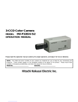
Hitachi KP-FD140GV, KP-F140GV, KP-F33GV, KP-F83GV, KP-FD33GV, KP-FD83GV Operating instructions

  • Hello! I am an AI chatbot trained to assist you with the Hitachi KP-FD140GV Operating instructions. I’ve already reviewed the document and can help you find the information you need or explain it in simple terms. Just ask your questions, and providing more details will help me assist you more effectively!
CCD camera
KP-FD140GV
KP-FD83GV
KP-FD33GV
KP-F140GV
KP-F83GV
KP-F33GV
O p e r a t i o n M a n u a l
Hitachi Kokusai Electric Inc.
RoHS Compliant
These products comply with the requirement of
the RoHS (Restriction of the use of Certain
Hazardous Substances in Electrical and electronic
Equipment) Directive 2002/95/EC.
Thank you for purchase this fine Hitachi Kokusai
Electric CCD camera.
Before using the camera, please read this operation
manual carefully and keep this manual on file for
ready reference in the future.
September 19, 2008 Version 1.06
A
IMPORTANT SAFETY INSTRUCTIONS
1. Read Instructions
All the safety and operating instructions should be read before the product is operated.
2. Retain Instructions
The safety and operating instructions should be retained for future reference.
3. Heed Warnings
All warnings on the product and the operating instructions should be adhered to.
4. Follow Instructions
All operating and use instructions should be followed.
5. Cleaning
Unplug this product from the wall outlet before cleaning. Do not use liquid cleaners or aerosol cleaners. Use a
damp cloth for cleaning.
6. Attachments
Do not use attachments not recommended by the product manufacturer as they may cause hazards.
7. Water and Moisture
Do not use this product near water - for example, near a bath tub, wash bowl, kitchen sink, or laundry tub; in a wet
basement; or near a swimming pool; and the like.
8. Accessories
Do not place this product on an unstable cart, stand, tripod, bracket, or table. The product may fall, causing serious
injury to a child or adult, and serious damage to the product. Use only with a cart, stand, tripod, bracket, or table
recommended by the manufacturer, or sold with the product. Any mounting of the product should follow the
manufacturer's instructions, and should use a mounting accessory recommended by the manufacturer.
9. Moving
A product and cart combination should be moved with care.
Quick stops, excessive force, and uneven surfaces may cause the product and cart combination to overturn.
10. Ventilation
Slots and openings in the cabinet are provided for ventilation and to ensure reliable operation of the product and to
protect it from overheating, and these openings must not be blocked or covered.
The openings should never be blocked by placing the product on a bed, sofa, rug, or other similar surface. This
product should not be placed in a built-in installation such as a bookcase or rack unless proper ventilation is
provided or the manufacturer's instructions have been adhered to.
11. Power Sources
This product should be operated only from the type of power source indicated on the marking label. If you are not
sure of the type of power supply to your home, consult your product dealer or local power company. For products
intended to operate from battery power, or other sources, refer to the operating instructions.
12. Grounding or Polarization
This product is equipped with a three-wire grounding-type plug a plug having a third (grounding) pin. This plug will
only fit into a grounding-type power outlet. This is a safety feature. If you are unable to insert the plug into the outlet,
contact your electrician to replace your obsolete outlet. Do not defeat the safety purpose of the grounding-type plug.
13. Power-Cord Protection
Power-supply cords should be routed to that they are not likely to be walked on or pinched by items placed upon or
against them, paying particular attention to cords at plug, convenience receptacles, and the point where they exit from
the product.
14. Lightning
For added protection for this product during a lightning storm, or when it is left unattended and unused for long periods
of time, unplug it from the wall outlet. This will prevent damage to the product due to lightning and power-line surges.
15. Overloading
Do not overload wall outlets, extension cords or integral convenience receptacles as this can result in a risk of fire or
electric shock.
16. Object and Liquid Entry
Never push objects of any kind into this product through openings as they may touch dangerous voltage points or
short-out parts that could result in a fire or electric shock. Never spill liquid of any kind on the product.
17. Inflammable and Explosive Substance
Avoid using this product where there are gases, and also where there are inflammable and explosive substances in the
immediate vicinity.
18. Heavy Shock or Vibration
When carrying this product around, do not subject the product to heavy shock or vibration.
19. Servicing
Do not attempt to service this product yourself as opening or removing covers may expose you to dangerous voltage
or other hazards. Refer all servicing to qualified service personnel.
20. Damage Requiring Service
B
Unplug this product from the wall outlet and refer servicing to qualified service personnel under the following
conditions:
a.When the power-supply cord or plug is damaged.
b.If liquid has been spilled, or objects have fallen into the product.
c. If the product has been exposed to rain or water.
d.If the product does not operate normally by following the operating instructions. Adjust only those controls that are
covered by the operating instructions as an improper adjustment of other controls may result in damage and will
often require extensive work by a qualified technician to restore the product to its normal operation.
e. If the product has been dropped or damaged in any way.
f. When the product exhibits a distinct change in performance-this indicates a need for service.
21. Replacement Parts
When replacement parts are required, be sure the service technician has used replacement parts specified by the
manufacturer or have the same characteristics as the original part.
Unauthorized substitutions may result in fire, electric shock, or other hazards.
22. Safety Check
Upon completion of any service or repairs to this product, ask the service technician to perform safety checks to
determine that the product is in proper operating condition.
23. Wall or Ceiling Mounting
The product should be mounted to a wall or ceiling only as recommended by the manufacturer.
24. Heat
The product should be situated away from heat sources such as radiators, heat registers, stoves, or other products
(including amplifiers) that produce heat.
1. Alle Anweisungen lesen
Vor Betrieb des Erzeugnisses sollten alle Sicherheits-und Bedienungsanleitungen gelesen werden.
2. Die Anweisungen aufbewahren
Die Sicherheits-und Bedienungsanleitungen sollten fünftigen Bezug aufbewahrt werden.
3. Warnungen beachten
Die Warnungen auf dem Erzeugnis und in den Bedienungsanleitungen solten beachtet werden.
4. Anweisungen befolgen
Alle Bedienungsanleitung-und
Verwendungsanweisungen sollten befolgt werden.
5. Reinigung
Den Stecker des Geräts vor Reinigung aus der Steckdose ziehen. Keine flüssigen Reinigungsmittel oder Aerosolreiniger
verwenden. Zum Reinigen einen feuchten Lappen verwenden.
6. Zubehör
Nur vom-Hersteller des Erzeugnisses empfohlenes Zubehör verwenden, da es sonst zu Störungen kommen kann.
7. Wasser und Feuchtigkeit
Dieses Erzeugnis nicht in der Nähe von Wasser verwenden - z.B, in der Nähe einer Badewanne, eines Waschbeckens,
einer Küchenspüle, eines Waschzubers, in einem nassen Keller, in der Nähe eines Schwimmbeckens usw.
8. Aufstellung
Das Erzeugnis nicht auf einen unstabilen Wagen, Stand, Dreifuß, Träger oder Tisch stellen.
Das Erzeugnis kann sonst herunterfallen und ein kind oder einen Erwachsenen schwer verietzen.
Außerdem kann das Gerät schwer beschädigt werden. Nur mit einem Wagen, Stand, Dreifuß, Träger oder Tisch
verwenden, der vom Hersteller empfohlen oder mit dem Erzeugnis verkauft worden ist. Für jegliche Anbringung
sollten die Anweisungen des Herstellers befolgt werden, und das vom Hersteller empfohlene Anbringungszuber sollte
verwendet werden.
9. Eine Kombination von Erzeugnis und Wagen sollte vorsichtig bewegt werden
Schneller Halt, übermäßige Krafteinwirkung und unebene Oberflächen können Umkippen der kombination von
Erzeugnis und Wagen verursachen.
10. Ventilation
Schlitze und Öffnungen im Gehäuse dienen der Ventilation. Sie sind für zuverlässigen Betrieb des Gerätes und
Schutz vor Überhitzung erforderlich und dürfen nicht blockiert oder abgedeckt werden. Die Öffnungen sollten niemals
dadurch blockiert werden, daß, das Gerät auf ein Bett, ein Sofa, einen Teppich oder eine ähnliche Oberfläche gestellt
wird.
Das Gerät sollte nur dann in Einbauinstallierung wie in einem Bücherschrank oder einem Gestell verwendet werden,
wenn angemessene Ventilation vorgesehen ist bzw. Die Anweisungen des Herstellers befolgt worden sind.
11. Stromversorgung
WICHTIGE SICHERHEITSANWEISUNGEN
E
20. Dommages nécessitant réparations
Débrancher l’appareil de la source d’alimentation et confier les réparations á un personnel qualifié dans les cas
suivants:
a. Lorsque le cordon d’alimentation ou sa fiche sont endommagés
b. Si du liquide s’est renversé sur l’appareil ou que des objets sont tombés dedans
c. Si l’appareil a été exposé á la pluie ou á l’eau.
d. Si l’appareil ne fonctionne pas normalement lorsqu’on observe les instructions d’utilisation.
Ne régler que les commandes couvertes par le mode d’emploi ; en effet, un réglage incorrect des autres
commandes pourrait entrainer des dommages et nécessiteront souvent des travaux de réparation coûteux par un
technicien qualifié pour remettre l’appareil en état de marche.
e. Si l’appareil est tombé ou qu’il a été endommagé.
f. Si l’appareil affiche une nette modification de ses performances, cela signifie qu’il a besoin d’être réparé.
21. Piéces de rechange
Si l’on a besoin de piéces de rechange, veiller á ce que le technicien de réparation utilise exclusivement les piéces de
rechange spécifiées par le fabricant ou des piéces ayant les mêmes caractéristiques que les piéces d’origine. Les
piéces de rechange non autorisées risquent de provoquer un feu, un choc électrique et autres dangers.
22. Vérificaton de sécurité
Aprés tout travail d’entretien ou de réparation de l’appareil, demander au technicien de réparation d’effectuer les
vérifications de sécurité pour s’assurer que l’appareil est en bon état de marche.
23.Montage au mur ou au plafond
L’appareil ne pourra être monté au mur ou au plafond que de la maniére recommandée par le fabricant.
24. Chaleur
Eloigner l’appareil des sources de chaleur, telles que radiateurs, appareils de chauffage, cuisiniéres, et de tour produit
engendrant de la chaleur (y compris les amplificateurs).
IMPORTANT NOTICE
These products have been tested and found
to comply with the limits for a Class A digital
device, pursuant to Part 15 of the FCC Rules.
These limits are designed to provide
reasonable protection against harmful
interference when the equipment is operated
in a commercial environment. This
equipment generates, uses, and can radiate
radio frequency energy and, if not installed
and used in accordance with the instruction
manual, may cause harmful interference to
radio communications. Operation of this
product in a residential area is likely to cause
harmful interference in which case the user
will be required to correct the interference at
his own expense.
WARNING
Changes or modifications not expressly
approved by Hitachi Denshi responsible for
compliance could void the user’s authority to
operate the equipment.
This product does not exceed the class
A/class B limits for radio noise emissions
from digital apparatus as set out in the radio
interference regulations.
Le présent appareil n’émet pas de bruits
radioélectriques dépassant les limités
applicable aux appareils numériques de
classe A prescrites dans le rVglement sur le
brouillage radioélectrique édicter par le
ministére des communications du canada.
USA
For Canada
F
Phenomena inherent to CCD imaging device
The following phenomena are inherent to a charge coupled device imaging element and do not indicate
malfunction.
1) Smear and blooming
Vertical bands are visible when a strong light enters the scene. Adjust the camera aiming direction
carefully to avoid strong direct or reflected light.
2) Fixed pattern noise
High ambient temperature can cause fixed pattern noise to appear throughout the scene.
3) Moire
Interaction between patterns can produce an additional "phantom" pattern to appear. The CCD picture
elements (pixels) are arranged in a pattern, which can interact with a pattern in the scene (e.g., a performer
wearing a finely striped necktie) to result in a Moire pattern. The effect should be considered when selecting
costumes, props and other scene elements.
4) Ghosting
Strong direct or reflected light near an object of interest can cause ghosting of the object to appear in the
picture. The effect is more obtrusive with certain iris settings and lens types. Select the scene layout and
camera pointing direction carefully in order to avoid this effect.
Operating considerations Notes to users
1. Important safety notes
Use this camera with a 12VDC power supply,
Observe that flammable objects, water or metal do not enter the camera interior. These may lead to failure or accident.
Do not modify the camera or use the camera with external covers removed. These may cause failure, void any warranties
and pose a safety hazard.
Sop using the camera at the approach of electrical storm (thunder audible). Protect the camera from rain if using it
outdoors.
In event the camera shows any abnormality, switch off the camera and disconnect the power cord. Contract a Hitachi
Denshi service representative.
2. Handling
Do not attempt to remove cover.
When installing or removing a lens, be sure to use care that water or dust dose not enter the inside of the camera.
3. Installing and storage
Avoid installing or storing the camera in the following environments.
Environments exposed to direct sunlight, rain or snow.
Environments where combustible or corrosive gas exists.
Excessively warm or cold environment (Operating ambient temperature: -10 to 50℃).
Humid or dusty environment.
Place subjected to excessive vibration or shock.
Environment exposed to strong electric or magnetic field.
Do not aim the camera lens at the sun.
Do not shoot strong light.
When such a scene is shot, vertical trailing will appear. However, this is not due to failure. In case strong light enters camera
through the lens, partial deterioration in picture quality will result.
4. To obtain stable performance for long time
When the camera is used continuously for long time under high ambient temperature, the inside electrical parts become
deteriorated, resulting in shortening its life. To use the camera continuously for long time, the highest temperature must be
below 40.
5. Connectors
Confirm the power is off before connecting or disconnecting a signal cable. Grasp connectors by the body, not the attached
G
wires.
6. Cleaning
Use a blower or a lens brush to remove dusts on the lens or the optical filter.
Wipe dirts on the case off with dry soft cloth. If dirks are hardened, wipe them off with cloth moistened with neutral
detergent liquid; wipe the cover with dry cloth.
Do not use benzene, thinner, alcohol, liquid cleaner or spray-type cleaner.
In event dust or other debris is lodged between the CCD and optical filter, consult dealer for cleaning by an optical
technician.
1
Overview
KP-FD140GV/FD83GV/FD33GV are Gigabit Ethernet output type color camera which utilized the progressive scan CCD
image sensor with square pixel which adopted the RGB primary color mosaic filter. KP-F140GV/F83GV/F33GV are black and
white type.
Since these cameras are Power over Ethernet (PoE) type, power supply is input via LAN cable.
Standard composition
Check when unpacking
Camera (with IR cut filter / Dummy grass) ·································· 1
CD ROM (Documents, Driver and SDK) ········································· 1
Composition table ·················································································· 1
Features
・High resolution
The 1/2-inch 1.45 million pixels (KP-FD140GV/F140GV), the 1/3-inch 0.8 million pixels (KP-FD83GV/F83GV) and the 1/3-
inch 0.33 million pixels (KP-FD33GV/F33GV) square lattices CCD achieve a high resolution.
・Gigabit Ethernet
By adoption of Gigabit Ethernet interface, high-speed connection of maximum of 1 Gbps can be possible. Moreover, by using
hub or switcher, construction of multiple camera system can be easily performed.
It is also possible to 100m.
・High color fidelity
RGB primary color mosaic filter and 6 color independent achieve a high resolution and high color fidelity.
・Power over type Ethernet
Power supply can be input via Ethernet cable.
Optional accessories
(1) 12 pin plug HR10A-10P-12S(01)
(2) Junction box JU-F30/JC-100
(3) Dummy glass (AR coated) ARC1214
(4) IR cut filter IRC650
(5) Tripod adaptor TA-M1
(6) LAN cable (CAT5E or CAT6)
(7) Camera cable
Shield type
2m
C
-
201KSM
C
-
201KSS
5m
C
-
501KSM
C
-
501KSS
10m
C
-
102KSM
C
-
102KSS
In the CE Marking region, use the shied type and install
clamp filter (ZCAT 2035-0930A: TDK) at both ends (camera
and video processor ends).
Ethernet is a trademark of XEROX Corporation.
2
Section name and functions
Camera mounting
Attached optional accessory the tripod adaptor "TA-M1", mount the camera to a tripod or mounting bracket.
Lens
Ethernet connector
Use for digital video output and
camera control signal input/
output signal.
Camera / Tripod adaptor
mounting screw holes
Lens mount
(C mount
DC IN/SYNC connector
Use for DC+12V power or external
trigger /VD signal input.
Camera / Tripod adaptor
mounting screw holes
CAUTION
Observe the dimensions of the lens mounting selection as
illustrated at the right.
If the dimensions are not observed, do not use such a lens,
because the lens and the camera will be damaged.
Lens flange
Lens optics
Max 9mm
Screw type: U1/4-20
Length = 4 to 5.5mm
Screws longer than 5.5 mm can cause internal damage, while less
than 4 mm prevents secure fastening and risks dropping to cause
damage and injury.
L
3
Optical filter
How to remove the IR cut filter / Dummy grass (*).
(1) Remove two screws and filter holder will come off.
(2) Remove the IR cut filter / Dummy grass from filter frame ④.
(3) Then, reinstall and secure filter holder with two screws ①.
Note: Prior to removing the optical filter, be sure to turn off the power.
Since garbage etc. invades into image reception surface camera,
please work under the clean air, such as a CLEAN ROOM.
* IR cut filter is equipped in the KP-FD140GV/FD83GV/FD33GV.
Dummy grass is equipped in the KP-F140GV/F83GV/F33GV.
1
2
3
4
4
Connector
1. Ethernet connector
PIN NO.
Signal
1 TRP1+
2 TPR1-
3 TPP2+
4 TRP3+
5 TRP3-
6 TRP2-
7 TRP4+
8 TRP4-
Status LED 1 LED 2
Immediately after Power ON Green Light On Yellow Light On
1Gb Transmission Green Light On Yellow Blink On
100Mb Transmission Red Light On Yellow Blink On
2. DCIN/SYNC connector
PIN NO.
Signal PIN NO.
Signal
1 GND (+12V) 7 TRIG-A / VD (H)
2 +12V 8 TRIG-B (C)
3 GND 9 TRIG-B (H)
4 N.C. 10 FLASH / VD OUT
5 GND 11 N.C.
6 N.C. 12 TRIG-A / VD (C)
Connector (matching camera: SNH-10-12(RPCB) SANWOO or equivalent
Plug (matching cable plug : HR10A-10P-12S(01) HIROSE or equivalent
In the CE Marking region, use the shied type and install clamp filter (ZCAT 2035-0930A: TDK) at both ends (camera
and video processor ends).
Please do not connect 1 pin and 3/5 pin when using PoE. When connecting it, PoE may stop the power supply.
Because TRIG-A/VD and TRIG-B are photo coupler input, 8/12 pin is isolated with 1/3/5 pin. When 8/12 pin is
connected to GND, please connect to 3 pin or 5 pin.
(Note) Please do not unplug and insert cable (digital out cable) with a power supplied to a camera.
Install clamp filter (ZCAT2035-0930A: TDK) at both ends (camera and video processor ends) in the CE marking legion.
LED 1 LED 2
5
System example
KP-FD140GV/F140GV/FD83GV/F83GV/FD33GV/F33GV connect to PC using LAN cable.
(*) Note that following point when connecting the camera
(1) Please connect the camera to device for Gigabit Ethernet (1000BASE-T).
(2) Please use LAN cable of CAT5E or more (recommendation: CAT6 straight cable).
(3) To the NIC for Jumbo frame is recommended to be used
Recommended NIC: Intel Pro1000 PT Desktop
(4) When the camera is connected to Laptop PC, please use the one whose built-in LAN is Gigabit Ethernet
(1000BASE-T) correspondence.
The external LAN card (CardBus32 or USB2.0) may not display the cameras ability because of the bus limitation.
ExpressCard is corresponded on the standard but useable product is unconfirmed (.as of April, 2008).
(5) This product prepares the high-performance driver (TurboLinx) and the filter driver (BroadLinx). Please use the driver
according to the usage referring to following specifications.
High-performance driver Filter driver
Corresponded NIC Intel Pro1000series Gigabit Ethernet NIC
Other network (In-house LAN, internet etc.) Unusable *1 Usable
CPU load Small Large
*1: When using high-performance driver, please configure the NIC setting before installation the driver.
(6) Please connect the camera and PC by 1 to 1 as much as possible
Please use the device corresponded to Jumbo frame when using the switching hub etc.
(7) A striped noise might be caused according to the equipment (hub etc.) connected with the camera.
In that case, please connect the cable to another port of the equipment again.
KP-FD140GV
LAN cable
(CAT5E/CAT6)
HITACHI
PC with NIC
for Gigabit
JU-F30
Camera cable
+12V
KP-FD140GV
HITACHI
PoE hub
LAN cable
(CAT5E/CAT6)
6
Functions and operations
Various mode setup and adjustment of KP-FD140GV/F140GV/FD83GV/F83GV/FD33GV/F33GV are performed by the remote
control via Gigabit Ethernet. Operation and adjustment way of function utilized are described below.
(Standard) means the function based on GenICam Standard Feature Naming Convention (SFNC) and (Custom) means the
original function. The software for GenICam can operate by using command name. Moreover, it can also be operated by reading
/writing the value to address directly.
1. Commands for acquisition
(1) ACQUITION Setting for image acquisition method
・MODE Select of mode
Command name AcquitionMode (Standard)
Address A0030000 h
Values (Factory setting 1) 1 "Continuous" Frames are captured continuously until stopped with the STOP command.
2 "MultiFrame" The number of frames specified by FRAME COUNT is captured.
3 "SingleFrame" One frame is captured.
・START Acquisition start
Command name AcquiationStart (Standard)
Address A0030004 h
Values (write only) 1 Start the acquisition of the camera image.
・STOP Acquisition stop
Command name AcquitionStop (Standard)
Address A0030008 h
Values (write only) 0 Stop the acquisition of he camera image.
・FRAME COUNT Set the number of capture *using when MODE is MultiFrame
Command name AcquitionFrameCount (Standard)
Address A003000C h
Values (Factory setting 1) 1 to 255 Set the number of frames to be acquired in MultiFrame mode.
・FRAMERATE RAW Acquisition frame rate
Command name AcquitionFrameRateRaw (Standard)
Address A0030014 h
Values (Factory setting 30: KP-FD140GV/F140GV
36: KP-FD83GV/F83GV
90: KP-FD33GV/F33GV)
7 to 30: KP-FD140GV/F140GV
7 to 36: KP-FD83GV/F83GV
7 to 90: KP-FD33GV/F33GV Control the Frame rate in 1 fps step.
* Refer to page 19 "Frame rate"
GENiCAM
TM
is a trademark of EMVA (European Machine Vision Association).
7
2. Commands for acquisition image
(1) WIDTH MAX Maximum width of the image
Command name WidthMax (Standard)
Address A002F008 h
Values (read only) 1360: KP-FD140GV/F140GV
1024: KP-FD83GV/F83GV
656: KP-FD33GV/F33GV
(2) HEIGHT MAX Maximum height of the image
Command name HeightMax (Standard)
Address A002F00C h
Values (read only) 1024: KP-FD140GV/F140GV
768: KP-FD83GV/F83GV
492: KP-FD33GV/F33GV
(3) WIDTH Set the actual image width
Command name Width (Standard)
Address A0020000 h
Values (Factory setting 1280: KP-FD140GV
1360: KP-F140GV
1024: KP-FD83GV/F83GV
652: KP-FD33GV/F33GV)
2 to WIDTH MAX Set the actual image width at intervals of 2 pixels.
(4) HEIGHT Set the actual image height
Command name Height (Standard)
Address A0020004 h
Values (Factory setting 960: KP-FD140GV
1024: KP-F140GV
768: KP-FD83GV/F83GV
490: KP-FD33GV/F33GV)
2 to HEIGHT MAX Set the actual image height at intervals of 2 pixels.
(5) OFFSET Setting of start position of the actual image
・OFFSET X Set the horizontal offset
Command name OffsetX (Standard)
Address A0020008 h
Values (Factory setting 0) 0 to (WIDTH MAX - WIDTH - 2)
Set the horizontal start position of the actual image at intervals of
2 pixels.
・OFFSET Y Set the vertical offset
Command name OffsetY (Standard)
Address A002000C h
Values (Factory setting 0) 0 to (HEIGHT MAX - HEIGHT - 2)
Set the vertical start position of the actual image at intervals of
2 pixels.
(6) BINNING Setting of the binning mode * for only KP-F140GV/F83GV/F33GV
・VERTICAL Set the number of vertical photo-sensitive cell
Command name BinningVertical (Standard)
Address A0020010 h
Values (Factory setting 1) 1 to 2 When set to 1, not perform the binning mode.
When set to 2, the vertical image size is half and frame rate is
8
increased about 2 times.
(7) PIXEL FORMAT Setting of the pixel format
・PIXEL FORMAT Set the pixel format
Command name PixelFormat (Standard)
Address A0020014 h
Values *Refer the following table Following format is available
Format Values Available for
Mono8 01080001
16
All models
Mono10 01100003
16
All models
Mono12 01100005
16
All models
BayerRG8 01080009
16
only KP-FDXXGV
BayerRG10 0110000D
16
only KP-FDXXGV
BayerRG12 01100011
16
only KP-FDXXGV
RGB8Packed 02180014
16
only KP-FDXXGV
BGR8Packed 02180015
16
only KP-FDXXGV
RGB10V1Packed 0220001C
16
only KP-FDXXGV
RGB12Packed 02180018
16
only KP-FDXXGV
YUV422Packed 0210001F
16
only KP-FDXXGV
YUV422_10Packed 80180001
16
only KP-FDXXGV
YUV422_12Packed 80180002
16
only KP-FDXXGV
(8) PIXEL COLOR FILTE Kind of color filter equipped the camera
・MODE Select the mode
Command name PixelColorFilter (Standard)
Address A0020018 h
Values (read only) 0 "BayerRG" When PixelFormat is BayerRG8/10/12 (KP-FD140GV/FD83GV/FD33GV)
4 "None" Others
(9) PARTIAL SCAN Setting of the partial scan
・MODE Select the mode
Command name PartialScanMode (Custom)
Address A0FF0100 h
Values (Factory setting 0) 0 "Off" Not perform the partial scan.
1 "On" Perform the partial scan and frame rate is increased. *Refer to page 22
*Note: when WIDTH or HEIGHT is set to 16 or less, AGC and AES may not operate.
9
3. Commands of the image adjustment
(1) BLACKLEVEL Setting of master black level
・MODE Select the mode
Command name BlackLevelMode (Custom)
Address A0F70000 h
Values (Factory setting 1) 0 "Off" Not perform the master black adjustment.
1 "On" Perform the master black adjustment according to a set value.
・LEVEL Adjustment of master black level
Command name BlackLevelRaw (Standard)
Address A0070014 h
Values (Factory setting 128): 0 to 255 Black level is reduced at 0 side and raised at 255 side.
(2) SHRAPNESS Setting of object contour correction
・MODE Select the mode
Command name SharpnessMode (Custom)
Address A0FF0000 h
Values (Factory setting 0) 0 "Off" Not perform the contour correction.
1 "On" Perform the contour correction according to a set value.
・LEVEL Adjust sharpness level
Command name SharpnessRaw (Custom)
Address A0FF0004 h
Values (Factory setting 0) 0 to 255 Setting value toward 0 side reduces correction for soft contour and 255 side
increase correction for sharper contours.
(3) MANUAL GAIN Setting of electrical sensitivity
・MODE Select the mode
Command name GainMode (Custom)
Address A0F70004 h
Values (Factory setting 1) 0 "Off" Not perform the gain adjustment.
1 "On" Perform the gain adjustment according to a set value.
・LEVEL1 Adjust electrical sensitivity 1
Command name GainRaw (Standard)
Address A0070004 h
Values (Factory setting 0) 0 to 503 Adjust the gain level from 0 to 18dB in 504 steps at intervals of 0.0358dB.
・LEVEL2 Adjust electrical sensitivity 2
Command name GainAbs (Standard)
Address A0070008 h
Values (Factory setting 0) 0.0 to 18.0 Adjust the gain level from 0 to 18dB in 181 steps at intervals of about 0.1dB.
(4) AUTO GAIN CONTROL Adjust electrical sensitivity automatically (AGC)
・MODE Select the mode
Command name GainAuto (Standard)
Address A007000C h
Values (Factory setting 0) 0 "Off" Not perform the auto gain control.
2 "Continuous" The video level is automatically adjusted in the range of 0 to 18dB.
*This command is given to priority more than MANUAL GAIN.
(5) MANUAL WHITE BALANCE Setting of manual white balance *for only KP-FD140GV/FD83GV/FD33GV
・MODE Select the mode
Command name BalanceRatioMode (Custom)
Address A0F70008 h
Values (Factory setting 0) 0 "Off" Not perform the white valance adjustment.
1 "On" Adjust Red/Blue gain level according to a set value.
10
・SELECTOR Switch the adjustment color (RED / BLUE)
Command name BalanceRatioSelector (Standard)
Address A0070024 h
Values (Factory setting 1) 1 "Red" Switch the color adjusted at MODE/LEVEL Red.
3 "Blue" Switch the color adjusted at MODE/LEVEL Blue.
・LEVEL (related to SELECTOR) Adjust the RED / BLUE gain
Command name BalanceRatioAbs (Standard)
Address A0070024 h
Values (Factory setting 128): 0 to 255 Adjust the RED / BLUER gain in 256 steps.
(6) AUTO WHITE BALANCE Setting of auto white balance *for only KP-FD140GV/FD83GV/FD33GV
・MODE Select the mode
Command name BalanceWhiteAuto (Standard)
Address A0070020 h
Values (Factory setting 0) 0 "Off" Not perform the auto white balance.
1 "Once" Adjust white balance automatically and change the value of BalanceRatioRaw.
2 "Continuous" White balance is adjusted in real time (automatic tracking).
*This command is given to priority more than MANUAL WHITE BALANCE.
(7) ELECTRIC SHUTTER Setting of electric shutter
・MODE Select the mode
Command name ExposureMode (Standard)
Address A0030040 h
Values (Factory setting 0) 0 "Off" The normal shutter (frame rate)
1 "Timed" Shutter speed according to setting.
2 "TriggerWidth" It become ONE trigger mode. *Refer to page 20 "Trigger mode"
(8) SHUTTER SPEED Setting of the shutter speed
・MODE Select the mode
Command name PresetShutter (Custom)
Address A0F30010 h
Values (Factory setting 255): 0 "Off" The normal shutter
1 "Preset1"
8 "Preset8" Select the shutter speed from following 8 step presets.
KP-FD140GV
KP-F140GV
KP-FD83GV
KP-F83GV
KP-FD33GV
KP-F33GV
Preset1
1/30s 1/36s 1/90s
Preset2
1/60s 1/60s 1/250s
Preset3
1/100s 1/125s 1/500s
Preset4
1/500s 1/500s 1/1000s
Preset5
1/1000s 1/1000s 1/2000s
Preset6
1/2000s 1/2000s 1/4000s
Preset7
1/10000s 1/10000s 1/10000s
Preset8
1/50000s 1/50000s 1/50000s
255 "Variable" Set the shutter speed in the range from 1/10000 to 10 second.
・VARIABLE1 Setting of the Variable shutter 1
Command name ExposureTimeAbs (Standard)
Address A0030044 h
Values (Factory setting 33333: KP-FD140GV/F140GV
27777: KP-FD83GV/F83GV
11111: KP-FD33GV/F33GV)
10 to 10000000 Set the shutter speed in the range from 1/100000 to 10 second in us.
11
・VARIABLE2 Setting of the Variable shutter 2
Command name ExposureTimeRaw (Standard)
Address A0030048 h
Values (Factory setting 834 = 342
16
: KP-FD140GV/F140GV
818 = 332
16
: KP-FD83GV/F83GV
771 = 303
16
: KP-FD33GV/F33GV)
0 to 1536 Set the shutter speed in the range from 10 to 1/100000 second in 1536
steps.
Setting value can be derived as follows. (
ShutterSpeed
: μsec)
a) Setting value XYY
16
obtained from exposure time.
9
100
1
10
1
16
1X
YY
X
edShutterSpe
edShutterSpe
int
))int(log(
b) Exposure time obtained from setting value XYY
16
.
sec])[(
9110
1
16
16
X
100
YY
edShutterSpe
Ex. 1 Exposure time = setting value XYY to obtain 1/125sec (= 8000μsec)
16
16
16
16
12
2C7XYY
C7
9
100
7
9
100
1
10
8000
YY
2
18000X


int
int
logint
Ex. 2 Setting value 25D
16
that produces 1/234.22 second exposure time.
[sec]
sec][
)(
  
  
234.22
1
4269.53
9
100
5D
110
16
16
2
1
edShutterSpe
(9) AUTO ELECTRIC SHUTTER Setting of Auto Electric Shutter (AES)
・MODE Select the mode
Command name ExposureAuto (Standard)
Address A003004C h
Values (Factory setting 0) 0 "Off" AES is set to OFF.
2 "Continuous" Shutter speed is automatically adjusted in the range from normal shutter to
1/100000 second according to light source brightness
*This command is given to priority more than SHUTTER SPEED.
(10) GAMMA Setting of gamma correction
・MODE Select the mode
Command name GammaMode (Custom)
Address A0F70010 h
Values (Factory setting 1) 0 "Off" Not perform the gamma correction (γ=1).
1 "On" Adjust the detail gamma according to setting value.
・LEVEL Adjust gamma correction level
Command name GammaRaw (Custom)
Address A0F70014 h
Values (Factory setting 0) 0 to 255 Set gamma curve in 256 steps.
12
(11) ALC ADJUST Setting of Auto Level Control of image level (ALC)
・MODE Select the mode
Command name ALCAdjustMode (Custom)
Address A0FF0008 h
Values (Factory setting 0) 0 "Off" Convergence level when using AES or AGC is default.
1 "On" Convergence level is setting value set at VIDEO LEVEL.
・VIDEO LEVEL Setting value of video level when AGC or AES is ON
Command name ALCAdjustRaw (Custom)
Address A0FF000C h
Values (Factory setting 128) 0 to 255 Setting value toward 0 side decrease convergence level and 255 side
increase convergence level.
(12) MASKING Setting of 6 vector independent masking (primary color R G B and complementary color Ye Cy Mg
saturation and hue can be separately varied). *for only KP-FD140GV/FD83GV/FD33GV
・MODE Select the mode
Command name MaskingMode (Custom)
Address A0FF001C h
Values (Factory setting 0) 0 "Off" Not perform masking functions.
1 "On" Perform masking functions.
・SELECTOR Select the color done masking
Command name MaskingSelector (Custom)
Address A0FF0020 h
Values (Factory setting 1) 1 "Red" Perform masking function about Red.
2 "Green" Perform masking function about Green.
3 "Blue" Perform masking function about Blue.
4 "Cyan" Perform masking function about Cyan.
5 "Magenta" Perform masking function about Magenta.
6 "Yellow" Perform masking function about Yellow.
・SATURATION (related to SELECTOR) Adjust saturation of the color selected at SELECTOR
Command name SaturationRaw (Custom)
Address A0FF0024 h
Values (Factory setting 128) 0 to 255 Adjust the saturation of the color selected at SELECTOR in 256 steps.
・HUE (related to SELECTOR) Adjust hue of the color selected at SELECTOR
Command name HueRaw (Custom)
Address A0FF0028 h
Values (Factory setting 128) 0 to 255 Adjust the hue of the color selected at SELECTOR in 256 steps.
SELECTOR
Toward 0 side ... Toward 255 side ...
Red Come near to Yellow Come near to Magenta
Green Come near to Cyan Come near to Yellow
Blue Come near to Magenta
Come near to Cyan
Cyan Come near to Blue Come near to Green
Magenta Come near to Red Come near to Blue
Yellow Come near to Green Come near to Red
(13) PAINT BLACK Setting of paint black (color level of Red, Green and Blue can be separately varied)
*for only KP-FD140GV/FD83GV/FD33GV
・MODE Select the mode
Command name PaintBlackMode (Custom)
Address A0FF002C h
Values (Factory setting 0) 0 "Off" Not perform the paint black functions.
1 "On" Perform paint black functions.
Y
R
M
B
C
G
(0)
(255)
(255)
(0)
Saturation
Hue
13
・SELECTOR Switch the color doing Paint black
Command name PaintBlackSelector (Custom)
Address A0FF0030 h
Values (Factory setting 1) 1 "Red" Perform the paint black function about Red.
2 "Green" Perform the paint black function about Green.
3 "Blue" Perform the paint black function about Blue.
・LEVEL (related to SELECTOR) Adjust level of color selected at SELECTOR
Command name PaintBlackRaw (Custom)
Address A0FF0034 h
Values (Factory setting 0) 0 to 255 Adjust the color level of the color selected at SELECTOR in 256 steps.
(14) KNEE Setting of knee
・MODE Select the mode
Command name KneeMode (Custom)
Address A0FF0010 h
Values (Factory setting 0) 0 "Off" Not perform knee.
1 "On" Knee function provides natural graduation in bright portions.
・KNEE POINT Adjust knee point
Command name KneePointRaw (Custom)
Address A0FF0014 h
Values (Factory setting 0) 0 to 32 Setting value toward 0 side increase start level of knee and 32 side
decrease start level of knee.
・KNEE SLOPE Adjust knee slope
Command name KneeSlopeRaw (Custom)
Address A0FF0018 h
Values (Factory setting 0) 0 to 159 Setting value toward 0 side intensify effective of knee and 159 side weaken
effective of knee.
14
4. Commands of Input / Output signal
(1) TRIGGER Setting of the external trigger *Refer to page 21 "Trigger mode" about details of trigger mode
・SELECTOR Select the trigger action
Command name TriggerSelector (Standard)
Address A0030020 h
Values (Factory setting 1) 1 "FrameStart" Select this when using normal trigger mode.
2 "ExposureStart" Select this when using ONE trigger mode and trigger source is software.
3 "ExposureEnd" Select this when using ONE trigger mode and trigger source is software.
4 "FrameTransferStart" Select this when using reset control mode.
5 "VDReset" Select this when using VD reset mode.
・MODE (related to SELECTOR) Select the mode selected at SELECTOR
Command name TriggerMode (Standard)
Address A0030024 h
Values (Factory setting 0) 0 "Off" Set trigger mode selected at SELECTOR to OFF.
1 "On" Set trigger mode selected at SELECTOR to ON.
・SOURCE (related to SELECTOR) Select the trigger source selected at SELECTOR
Command name TriggerSource (Standard)
Address A003002C h
Values (Factory setting 0) 0 "Line1" Input trigger signal from 7 pin of DCIN/SYNC connector (TRIG A).
2 "Line3" Input trigger signal from 9 pin of DCIN/SYNC connector (TRIG B).
7 "Software" Use software trigger.
・POLARITY (related to SELECTOR) Select polarity of trigger signal selected at SELECTOR
Command name TriggerActivation (Standard)
Address A0030030 h
Values (Factory setting 1) 0 "FallingEdge" Falling of input signal is made into trigger signal.
1 "RisingEdge" Rising of input signal is made into trigger signal.
・SOFTWARE (related to SELECTOR) Generate the software trigger selected at SELECTOR
*using when SOURCE is Software
Command name TriggerSoftware (Standard
Address A0030028 h
Values (write only) 1 Whenever 1 is written, the software trigger is generated.
(2) TRIGGER DELAY Setting of trigger delay
・MODE Select the mode
Command name TriggerDelayMode (Custom)
Address A0F30004 h
Values (Factory setting 0) 0 "Off" Not perform trigger delay.
1 "On" Trigger delay is generated for the period set at DELAY TIME.
・DELAY TIME (related to SELECTOR of TRIGGER) Set the duration of trigger delay selected at SELECTOR
Command name TriggerDelayRaw (Standard)
Address A0030038 h
Values (Factory setting 0) 0 to 4096 Set the following range at intervals.
Camera Selector of Trigger Setting range Intervals
FrameStart 6.88 to 8196.88 us
FrameTransferStart
63.2 to 8253.2 us
KP-FD140GV
/F140GV
VDReset 10.0 to 8120.2 us
Approx. 2.0us
FrameStart 6.56 to 13110.56 us
FrameTransferStart
73.0 to 13181.0 us
KP-FD83GV
/F83GV
VDReset 11.2 to 13115.2 us
Approx. 3.2us
FrameStart 7.18 to 13111.18 us
FrameTransferStart
44.8 to 13148.8 us
KP-FD33GV
/F33GV
VDReset 6.8 to 13110.8 us
Approx. 3.2us
/