Page is loading ...

CAMERA CONTROL UNIT
CU-HD1000
OPERATING INSTRUCTIONS
Please read these operating instructions carefully for proper operation,
and keep them for future reference.
Note: The model and serial numbers of your product are important for you to keep for your convenience and
protection. These numbers appear on the nameplate located on he bottom of the product. Please record these
numbers in the spaces provided below, and retain this manual for future reference.
Model No.
Serial No.

A
SAFETY INSTRUCTIONS
Carefully read all safety messages in this manual and safety Instructions on your equipment.
Follow recommended precautions and safe operating practices.
SAFETY ALERT SYMBOL
This is the “Safety Alert Symbol.” This symbol is used to call your attention to items or operations
that could be dangerous to you or other persons using this equipment. Read these messages
and follow these instructions carefully.
It is essential that you read the instructions and safety regulations before you attempt to assemble or use
this equipment.
The definitions of signal words are as follows:
WARNING: Personal danger
Warning notes indicate any condition or practice, which if not strictly observed, could result
in personal injury or possible death.
CAUTION: Possible damage to equipment
Caution notes indicate any condition or practice, which if not strictly observed or remedied,
could result in damage or destruction of the equipment.
NOTE: Notes indicate an area or subject of special merit, emphasizing either the product′s
capabilities or common errors in operation or maintenance.
WARNING: TO REDUCE THE RISK OF FIRE OR ELECTRIC SHOCK, DO NOT EXPOSE THIS
COLOR CAMERA TO RAIN OR MOISTURE.
AVERTISSEMENT
Afin d’éviter tout risque d’incendie ou d’électrocution, ne pas exposer
l’appareil á la pluie ou á l’humidité.
Afin d’écarter tout risque d’électrocution, garder le coffret fermé. Ne confier
l’entretien de l’appareil qu á un personnel qualifié.
VORSICHT
Um Feuergefahr und die Gefahr eines eiektrischen Schiages zu vermeiden,
darf das Gerät weder Regen noch Feuchtigkeit ausgesetzt werden.
Um einen elektrischen Schiag zu vermeiden, darf das Gehäuse richt geöffnet werden.
Überiassen Sie Wartungsarbeiten stets nur einem Fachmann.
WARNING
CAUTION
NOTE
!
!
!
!

B
IMPORTANT SAFETY INSTRUCTIONS
1. Read Instructions
All the safety and operating instructions should be read before the product is operated.
2. Retain Instructions
The safety and operating instructions should be retained for future reference.
3. Heed Warnings
All warnings on the product and the operating instructions should be adhered to.
4. Follow Instructions
All operating and use instructions should be followed.
5. Cleaning
Unplug this product from the wall outlet before cleaning. Do not use liquid cleaners or aerosol cleaners. Use a damp
cloth for cleaning.
6. Attachments
Do not use attachments not recommended by the product manufacturer as they may cause hazards.
7. Water and Moisture
Do not use this product near water - for example, near a bath tub, wash bowl, kitchen sink, or laundry tub; in a wet
basement; or near a swimming pool; and the like.
8. Accessories
Do not place this product on an unstable cart, stand, tripod, bracket, or table. The product may fall, causing serious
injury to a child or adult, and serious damage to the product. Use only with a cart, stand, tripod, bracket, or table
recommended by the manufacturer, or sold with the product. Any mounting of the product should follow the
manufacturer's instructions, and should use a mounting accessory recommended by the manufacturer.
9. Moving
A product and cart combination should be moved with care.
Quick stops, excessive force, and uneven surfaces may cause the product and cart combination to overturn.
10. Ventilation
Slots and openings in the cabinet are provided for ventilation and to ensure reliable operation of the product and to
protect it from overheating, and these openings must not be blocked or covered.
The openings should never be blocked by placing the product on a bed, sofa, rug, or other similar surface. This
product should not be placed in a built-in installation such as a bookcase or rack unless proper ventilation is provided or
the manufacturer's instructions have been adhered to.
11. Power Sources
This product should be operated only from the type of power source indicated on the marking label. If you are not sure
of the type of power supply to your home, consult your product dealer or local power company. For products intended
to operate from battery power, or other sources, refer to the operating instructions.
12. Grounding or Polarization
This product is equipped with a three-wire grounding-type plug a plug having a third (grounding) pin. This plug will
only fit into a grounding-type power outlet. This is a safety feature. If you are unable to insert the plug into the outlet,
contact your electrician to replace your obsolete outlet. Do not defeat the safety purpose of the grounding-type plug.
13. Power-Cord Protection
Power-supply cords should be routed to that they are not likely to be walked on or pinched by items placed upon or
against them, paying particular attention to cords at plug, convenience receptacles, and the point where they exit from
the product.

C
14. Lightning
For added protection for this product during a lightning storm, or when it is left unattended and unused for long periods
of time, unplug it from the wall outlet. This will prevent damage to the product due to lightning and power-line surges.
15. Overloading
Do not overload wall outlets, extension cords or integral convenience receptacles as this can result in a risk of fire or
electric shock.
16. Object and Liquid Entry
Never push objects of any kind into this product through openings as they may touch dangerous voltage points or
short-out parts that could result in a fire or electric shock. Never spill liquid of any kind on the product.
17. Inflammable and Explosive Substance
Avoid using this product where there are gases, and also where there are inflammable and explosive substances in the
immediate vicinity.
18. Heavy Shock or Vibration
When carrying this product around, do not subject the product to heavy shock or vibration.
19. Servicing
Do not attempt to service this product yourself as opening or removing covers may expose you to dangerous voltage or
other hazards. Refer all servicing to qualified service personnel.
20. Damage Requiring Service
Unplug this product from the wall outlet and refer servicing to qualified service personnel under the following
conditions:
a. When the power-supply cord or plug is damaged.
b. if liquid has been spilled, or objects have fallen into the product.
c. If the product has been exposed to rain or water.
d. If the product does not operate normally by following the operating instructions. Adjust only those controls that are
covered by the operating instructions as an improper adjustment of other controls may result in damage and will often
require extensive work by a qualified technician to restore the product to its normal operation.
e. If the product has been dropped or damaged in any way.
f. When the product exhibits a distinct change in performance-this indicates a need for service.
21. Replacement Parts
When replacement parts are required, be sure the service technician has used replacement parts specified by the
manufacturer or have the same characteristics as the original part.
Unauthorized substitutions may result in fire, electric shock, or other hazards.
22. Safety Check
Upon completion of any service or repairs to this product, ask the service technician to perform safety checks to
determine that the product is in proper operating condition.
23. Wall or Ceiling Mounting
The product should be mounted to a wall or ceiling only as recommended by the manufacturer.
24. Heat
The product should be situated away from heat sources such as radiators, heat registers, stoves, or other products
(including amplifiers) that produce heat.

1
Outline and features
The CU-HD1000 is a camera control unit (CCU) for the newly developed multi-standard camera SK-
HD1000. The CU-HD1000 is compact (half rack/3 units), lightweight (7kg approx.), and provides
significantly reduced power consumption and improved operability. HD-SDI(1080i/720p) input/output
is mounted as standard. A flexible system capable of handling current SD-SDI and VBS formats can
be constructed.
Features
■ A flexible system capable of handling current HDTV and SDTV formats can be constructed.
HD/SD Digital
HD-SDI OUT x3, HD /SD-SDI OUTx3,
HD/SD-SDI PIX OUT x1, HD/SD-SDI RET IN x4
SD Analog (480i/576i) 16:9/4:3 switchable
VBS OUT x 3, PIX OUT x 1,
WFM OUT x 1, RET IN x 2
Component OUT (Y/P
B
/P
R
or R/G/B) x 1
■ High-performance down converter
1) The high-speed line conversion technology enables high resolution.
Equivalent to 840,000 pixel CCD
2) Built in independent video signal processing FPGA for SD signal which allows to adjust DTL
correction level independently.
3) A digital comb filter is available on VBS output for reducing cross color.
■ Built-in up converter
Built-in up converter in the CCU allows the SDTV return signal(480i/576i) to view in the HDTV View-
Finder at camera Head. The up converter has a pixel interpolation function to display a 1,920 x
1,080 effective scanning area.
■ High-quality transmission using a digital optical transmission system
An optical fiber composite cable is used to connect the camera head and CCU. The signals are
transmitted using an optical serial digital transmission method (HD-SDI standard/1.5 Gbps) to
ensure high-quality transmission.
The cable length can be extended up to 1 km.

2
Warnings and cautions when using
CAUTION
Do not disassemble or modify
The camera contains precision internal
components. Do not open the cover or disturb
switches and controls other than designated.
There is risk of impaired performance and
damage.
Keep foreign object out of interior
Entry of water, metallic or other foreign
materials can cause failure and damage.
Select use and storage locations carefully
Avoid using or storing the equipment in the
following types of locations. Impaired
performance and damage can be caused.
yExtremely hot or cold locations (exceeding 0
to 40°C), such as in enclosed vehicles.
ySubject to strong vibration.
yHumid or dusty locations.
ySalt spray or corrosive gases.
yStrong electromagnetic fields (e.g., near TV or
radio transmitters).
yWhere exposed to rain.
When connecting and disconnecting cables,
grasp the connector by the body, not the
attached cable. Cables can be damaged by
pulling on them.
Fuse replacement
Important: Although spare fuses are provided,
the fuse must be replaced only by a qualified
service technician.
In event of difficulty
Disconnect from power and contact the nearest
Hitachi Kokusai Electric service agency.
3
Warnings and cautions when using
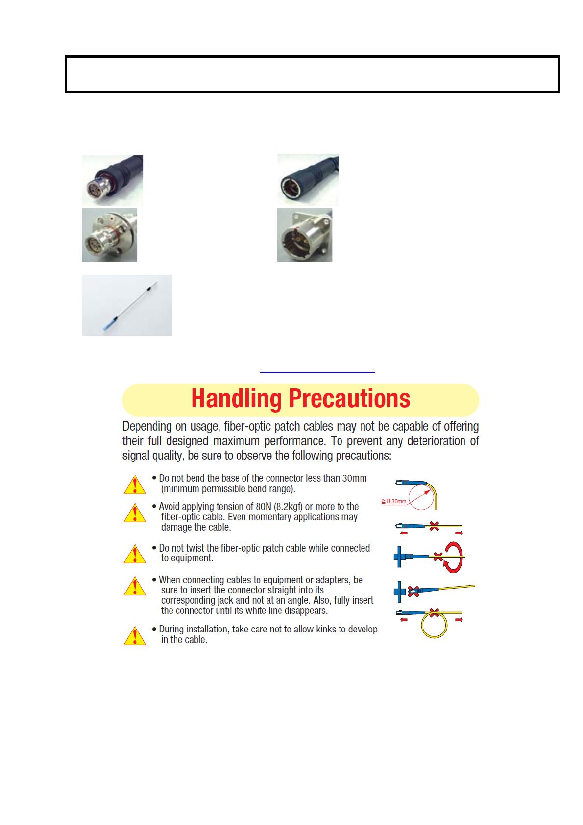
Hybrid Fiber Optical Camera Cable & Connector Handling
CU-HD1000 camera is using the optical fiber cable & connector which is required special
technique for handling.
1. Cable Connector & Receptacle
(1)
FCF (Fiber Cable Female) (2) FCM (Fiber Cable Male)
(3) FCFR (Female Receptacle) (4)FCMR (Male Receptacle)
2. Maintenance tool & information
(1)
Cleaning Stick (CANARE CLETOP 2.5/2.0)
(2) CLEANING KIT
Fiber optical cable assembly manufacture “CANARE” has Cleaning kit for the optical fiber cable
& connector available. Detail is in URL http://www.canare.co.jp
4
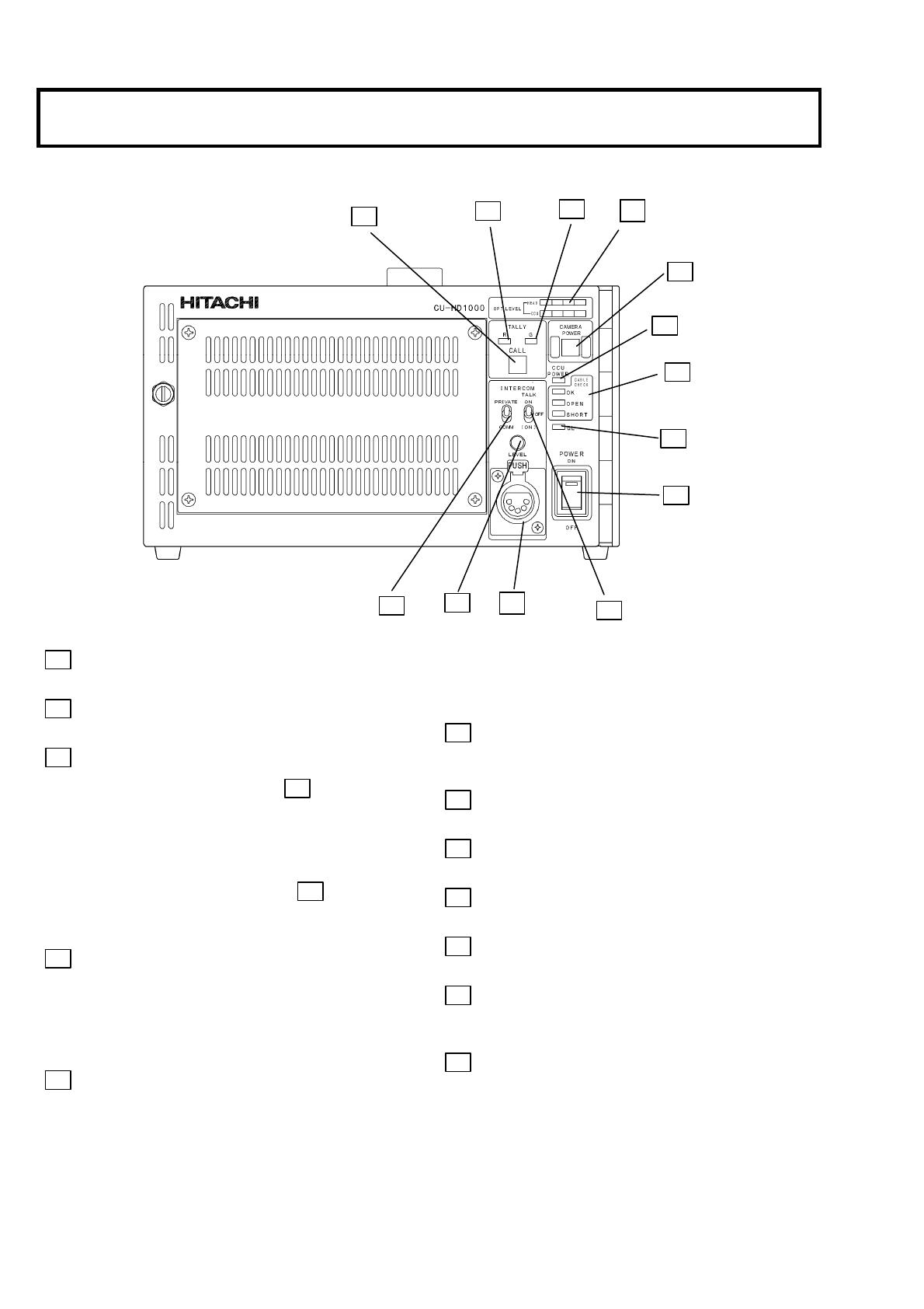
Facility names and functions
1 CCU POWER switch
CCU power on/off switch.
2
CCU POWER LED
Lights when power is on.
3
CABLE CHECK LED
OK: CAMERA POWER switch 4
can be
operated.
OPEN: Fiber cable not connected.
SHORT: Excess current in fiber cable.
Note: CAMERA POWER switch 4
is
inoperative when OPEN, SHORT LED is
lighted.
4 CAMERA POWER switch
Camera power on/off switch; lights at power on.
When the camera power is off, only one channel
intercom (CH1) is available.
Press the switch for 3 sec. or more, the camera power
turns off.
5
GL ON LED
Lights during genlock operation.
Note: When a different frame rate signal is input for
genlock, the LED blinks and the signal is
ignored.
6
R TALLY LED
Lights at red tally input or when sending CALL
signal from camera.
7
G TALLY LED
Lights at green tally input.
8
CALL button
Press to call the camera.
9
INTERCOM LEVEL control
Adjusts intercom listening volume.
10
TALK ON/OFF switch
Intercom microphone on/off switch.
11
PRIVATE/COMM switch
PRIVATE: Communicate with camera only
COMM:
Communicate with entire system
12
Intercom connector (XLR,5P)
Connection for optional MT-12MF headset.
8
6
7
4
2
3
5
1
10
11
12
9
27

5
Facility names and functions
13 HD SDI OUT connectors (BNC)
Outputs three lines of digital serial HDTV video
signals.
14
HD/SD SDI connectors (BNC)
Outputs four lines of digital serial HDTV/SDTV
video signals.
Select the HD-SDI or SD-SDI by the user function
menu.
The character is superimposed in PIX output.
15
D.RET input connectors (BNC)
Inputs for digital serial AUX video signals.
A signal selected among these four inputs is sent to
the camera viewfinder or the SK-HD1000’s RET
connector
The signal can be selected by user function menu..
16
ENCR OUT connectors (BNC)
Composite video outputs for 3 lines.
17
COMPONENT/RGB connectors (BNC)
R, G, B or Y, Pb, Pr signal outputs.
The output signals are selected by menu.
Important notice
18 PIX OUT connector (BNC)
Composite or R/G/B video output with superimposed
character.
19
WFM OUT connector (BNC)
Composite or R/G/B video output for waveform
monitor.
20 Analog RET-1 input connectors (BNC)
Inputs for analog AUX video signals. The signal is
sent to the camera viewfinder or the SK-HD1000
RET connector (selected by pressing RET1 of the
CA-HF1000).
21
Analog RET-2 input connectors (BNC)
Same function as analog RET-1.
22
PROMPT connectors (BNC)
Input for the prompter video signal. The signal is sent
to the CA-HF1000 PROMPT out connector.
When using return video, please input correct format signal which is selected on
the return assignment menu (page 9).
14
16
19
22
13
15
17
18
23
26
21
20
35
36
37
33
29
30
24
25
28
31
32
34
38
6
Facility names and functions
23
Genlock connectors (BNC)
Input for tri-level sync signal or black burst signal
for genlock operation.
24
AC IN connector
Input for AC power supply.
25
FG terminal
Frame ground terminal.
26
Fiber connector
Connect Fiber cable.
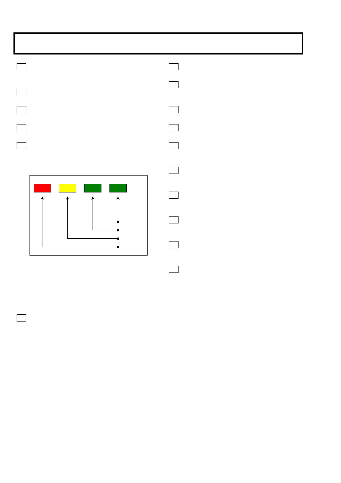
27
Receiver Level LED
The strength of the arriving light signal via fiber
cable is indicated by position of lighting LED.
ndicate the receiver level approximately
GREEN1: -3dBm to -8dBm (Normal)
GREEN2: -8dBm to -11dBm
YELLOW: -11dBm to -14dB (Warning)
RED: under -14 dB (Alarm)
28
REMOTE1 connector
Connection for the optional camera control panel or
setup control unit.
29
RS-232C connector
Use for camera control via RS-232C.
30
REMOTE2 connector
Connection for the optional camera control panel or
setup control unit.
31
TALLY OUT connector
Contact outputs for tally signals.
32
COMMUNICATION connector
Intercom and tally inputs from external system.
33
MIC REMOTE connector
This connector is used to select the MIC1 and
MIC2 amplifier gains.
34
WFM CONTROL connector
This connector is used to select the display mode of
the waveform monitor.
35
MIC OUT1 connector (XLR 3 pin)
Outputs MIC1 audio signals from a camera or the
CA-HF1000 at 0 dBm.
36
MIC OUT2 connector (XLR 3 pin)
Outputs MIC2 audio signals from the CA-HF1000
at 0 dBm.
37
RJ-45 connector
This connector is used to connect expanded
functions such as a remote controller.
38
TALLY CONTACT/VOLTAGE
The TALLY input can be contact or voltage supply.
Set the TALLY switches according to the systems
connected to CU-HD1000 rear panel
COMMUNICATION connector.
GREEN1
GREEN2
YELLOW
RED

7
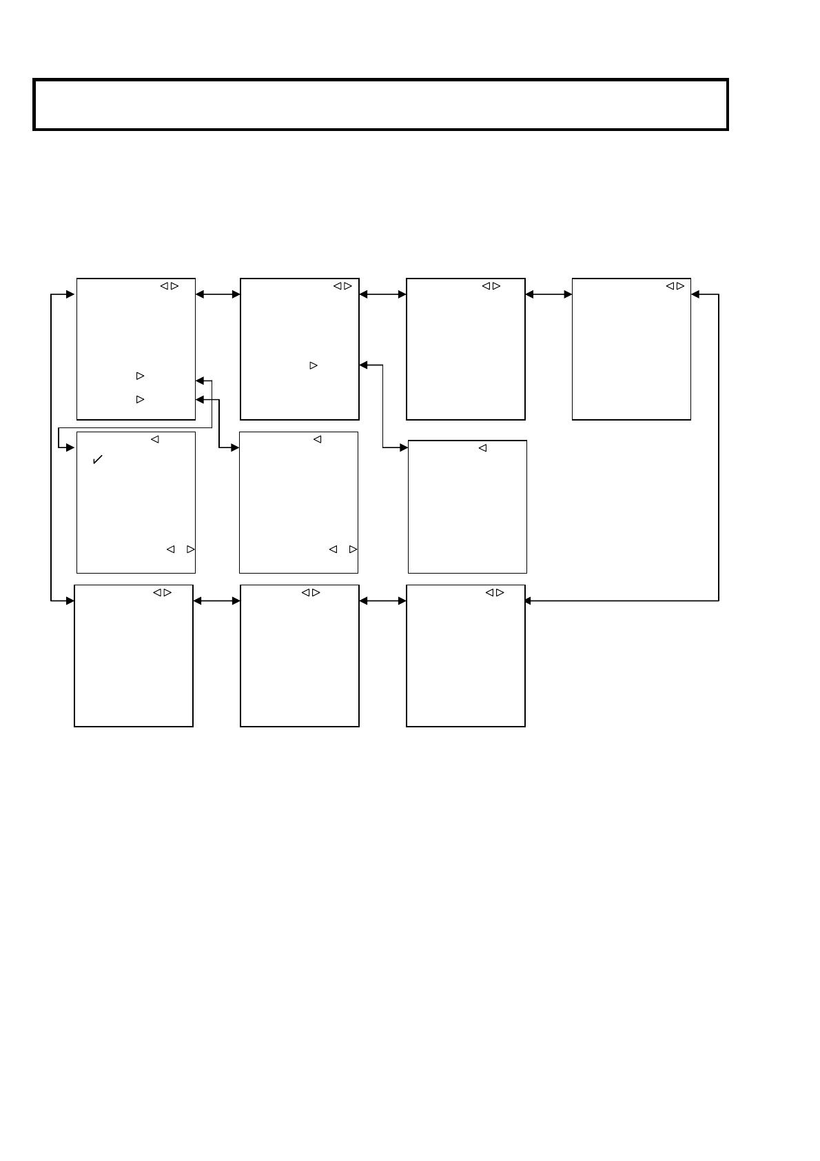
Function menu
Function menu
Use the camera control panel or the setup control unit connected to the CU-HD1000 rear side to display the function menus.
The function menus include the CCU menu to set the CU-HD1000 and the camera menu to set a camera.
(And also the function menus control the button of the TU-SD.Digital unit inside the CU-HD1000.)
ND CC
HEAD
MENU
CTL
HEAD
MASTER CAIN
SHUTTER
UP
DOWN
LEFT
RIGHT
MENU
RU-3400VR/JY-S10
RU-1200VR/JY
When MEMU button is active, ND button and
CC button are assigned for UP/DOWN and
LEFT/RIGHT respectively.
UP DOWN LEFT RIGHT SET
ADJUST
OFF ⇔ ON
CAM PWR
MENURIGHTLEFTDOWNUP
CU-HD1000
Right-front of TU-D.SD-DIGITAL unit
8
Function menu
CCU menu
If the FUNC button of the camera control panel is pressed with the color bar ON, the CCU menu is displayed.
Camera menu
The camera menu appears when the color bar is off. Contents differ by the camera. Refer to the camera operating instructions.
■RETURN SELECT
RET.CH SELECT
CH1 :D.RET1
CH2 :D.RET2
CH3 :A.RET1
CH4 :A.RET2
ASSIGNMENT :
■ASSIGNMENT
SELECT TYPE
D.RET1 :HD SDI
D.RET2 :HD SDI
D.RET3 :SD SDI 16:9
D.RET4 :SD SDI 4:3
A.RET1 :SD VBS 16:9
A.RET2 :SD VBS 4:3
■MIC GAIN
MIC1 :-60dB
MIC2 :-60dB
■SYSTEM TIMING
HD H PHASE : 0( 0)
SD SDI H P : 0( 0)
SD VBS H P : 108( 1728)
SC CORASE : 0°
SC FINE : 0( 0)
SD Y LEVEL : 0
C LEVEL : 0
■SD SETTING
OUTPUT :RGB
COMB FILTER :OFF
ASPECT :16:9
WFM :ENC
COMP SETUP :ON
R-Y/B-Y LEV :100%
■SD DTL
SD DTL :ON
H GAIN : 0
V GAIN : 0
H CRISP :-128
V CRISP :-128
DTL FREQ :5MHz
LEVEL DEP :-128
LEV DEP SLP:-128
■PIX DISPLY
FILTER :ON
ECC :ON
IRIS :ON
■TIME/DATE
DATE DISP :Y.M.D
TIME DISP :ON
YEAR :08
MONTH :01
DAY :01
HOUR :12
MINUTE :00
SET DATA :PUSH +
■TV FORMAT
□1080i
□720p
SET DATA :PUSH +
■CU-FUNCTION
BUZZER :ENABLE
SDI SELECT :HD SDI
SDI PIX :HD SDI
SDI AUDIO :OFF
CCU ID : 1
TV FORMAT: 1080i
50.00Hz
TIME/DATE: '08.01.01
12:00
9
Function menu
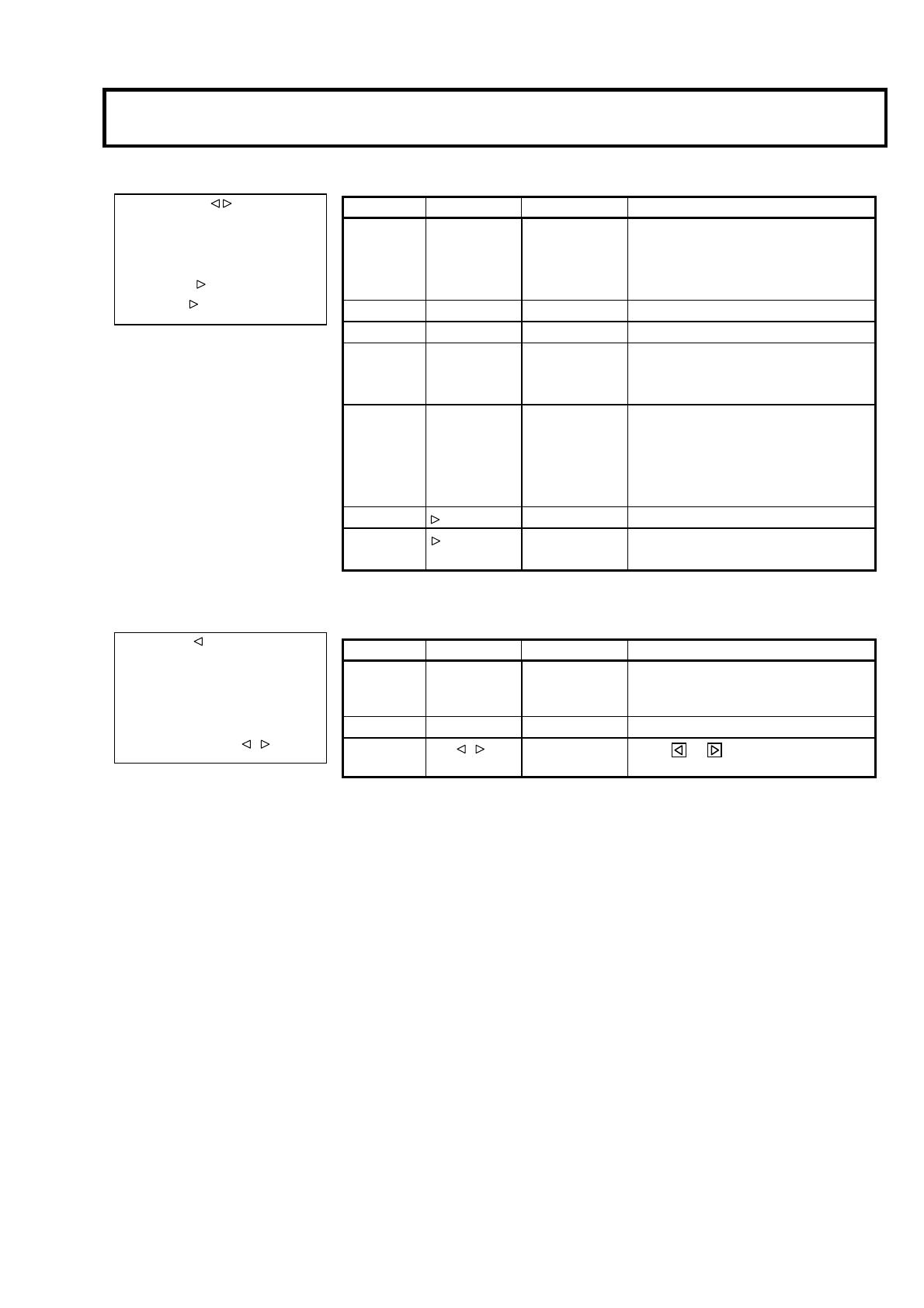
CU-FUNCTION menu
TV FORMAT menu
NOTICE:
The cursor is moved to an arbitrary format with an upper and lower switch, and when TV FORMAT is set, a right and left
switch is operated, and set. The ☑ mark is displayed by pushing a right and left switch, and TV FORMAT is changed.
After TV FORMAT is set, it saves the setting data by matching the cursor to “SET DATA", and pushing a right and left
switch at the same time. It returns to TV FORMAT before it changes automatically when it does not save the setting data
within ten seconds.
TV FORMAT returns to TV FORMAT before it changes automatically when the following operation is done.
(1) When it does not save the setting data within ten seconds.
(2) When it turns off the menu display before it saves the setting data.
(3) When it changes to “CU-FUNCTION MENU" before it saves the setting data.
(4) When it turns off the CCU power supply before is saves the setting data.
■CU-FUNCTION
BUZZER :ENABLE
SDI SELECT :HD SDI
SDI PIX :HD SDI
SDI AUDIO :OFF
CCU ID : 1
TV FORMAT: 1080i
50.00Hz
TIME/DAT: ’09.01.01
12:00
Item Setting Factory setting Description
BUZZER ENABLE, DISABLE ENABLE Sets buzzer operation during call input.
ENABLE :
Buzzer sounds.
DISABLE :
Buzzer does not sound.
SDI SELECT HD SDI, SD SDI HD SDI Sets output signal of HD/SD-SDI OUT connector.
SDI PIX HD SDI, SD SDI HD SDI Sets output signal of HD/SD-SDI OUT(PIX) connector.
SDI AUDIO ON,OFF OFF Sets the embedded audio ON/OFF of the HD-SDI /SD-SDI
output.
CCU ID 1
~
12 1 Set the CCU ID.
This ID is required for the SETUP CONTROL UNIT to
identify the CCU when the SETUP CONTROL UNIT is
used.
TV FORMAT Used to display the TV FORMAT submenu
TIME/DATE
Used to display the TIME/DATA submenu.
■TV FORMAT
☑1080i
□720p
SET DATA :PUSH +
Item Setting Factory setting Description
1080i
☑
,
□
☑
Select the TV FORMAT
1080i(HD-SDI IN/OUT)
☑:SELECTED
□:
NOT SELECTED
720p
☑
,
□
□
Select the TV FORMAT 720p(HD-SDI /INOUT)
SET DATA PUSH
+
- Press the
and
buttons together to enable the TV
FORMAT setting.
10
Function menu
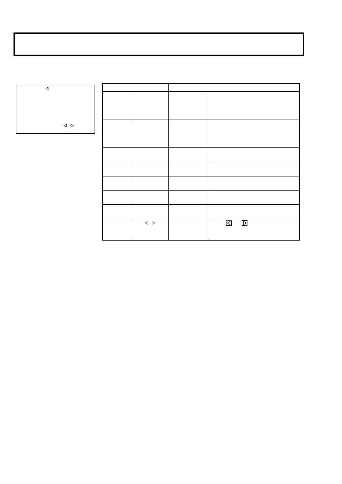
TIME/DATE menu
■TIME/DATE
DATE DISP :Y.M.D
TIME DISP :ON
YEAR :08
MONTH :01
DAY :01
HOUR :12
MINUTE :00
SET DATA :PUSH +
Item Setting Factory setting Description
DATE DISP OFF, Y.M.D,
M.D.Y, D.M.Y
Y.M.D
Sets the date display.
When ON is selected, the CU-FUNCTION menu displays
the date.
TIME DISP OFF, ON ON
Sets the time display.
When ON is selected, the CU-FUNCTION menu displays
the time.
YEAR 00
~
99 - Sets the year of the date.
MONTH 00
~
12 - Sets the month of the date.
DAY 00
~
31 - Sets the day of the date.
HOUR 00
~
23 - Sets the hours of the time.
MINUTE 00
~
59 - Sets the minutes of the time.
SET DATA PUSH
+
- Press the
and buttons together to enable the
TIME/DATE setting.

11
Function menu
RETURN SELECT menu
ASSIGNMENT menu
MIC GAIN menu
■RETURN SELECT
RET.CH SELECT
CH1 :D.RET1
CH2 :D.RET2
CH3 :A.RET1
CH4 :A.RET2
ASSIGNMENT :
■ASSIGNMENT
SELECT TYPE
D.RET1 :HD SDI
D.RET2 :SD SDI16:9
D.RET3 :SD SDI 4:3
D.RET4 :SD SDI
A.RET1 :SD VBS16:9
A.RET2 :SD VBS 4:3
Item Setting Factory setting Description
D.RET1 HD SDI
The transmission signal set to digital return 1 is selected.
D.RET2 HD SDI
The transmission signal set to digital return 2 is selected.
D.RET3 SD SDI 16:9
The transmission signal set to digital return 3 is selected.
D.RET4
HD SDI,
SD SDI16:9,
SD SDI 4:3,
SD SDI 4:3
The transmission signal set to digital return 4 is selected.
A.RET1 SD VBS16:9
The transmission signal set to analog return 1 is selected.
A.RET2
SD VBS16:9,
SD VBS 4:3
SD VBS 4:3
The transmission signal set to analog return 2 is selected.
Item Setting Factory setting Description
MIC1 GAIN -10dB, -20dB, -30dB,
-40dB, -50dB, -60dB, -70dB
-60dB Sets the sensitivity of the MIC1 line.
MIC2 GAIN -10dB, -20dB, -30dB,
-40dB, -50dB, -60dB, -70dB
-60dB Sets the sensitivity of the MIC2 line.
Control the MIC GAIN when it controls remotely the camera.
Not control the MIC GAIN when display the “*” sign.
Display the “*” sign when it doesn’t control remotely the camera.
Item Setting Factory setting Description
CH1 D.RET1
Selects the RET signal when the RET1 transmission signal
switch of the CA-HF1000 is set to 1.
CH2 D.RET1
Selects the RET signal when the RET2 transmission signal
switch of the CA-HF1000 is set to 2.
CH3 D.RET1
Selects the RET signal when the RET3 transmission signal
switch of the CA-HF1000 is set to 3.
CH4
D,RET1,
D,RET2,
D,RET3,
D,RET4,
A,RET1,
A,RET2
D.RET1
Selects the RET signal when the RET4 transmission signal
switch of the CA-HF1000 is set to 4.
ASSIGNMENT -
Used to display the ASSIGNMENT submenu.
■MIC GAIN
MIC1 :-60dB
MIC2 :-60dB
12
Function menu
SYSTEM TIMING menu
PIX DISPLAY menu
SD-DTL menu
■SD DTL
SD DTL :ON
H GAIN : 0
V GAIN : 0
H CRISP :-128
V CRISP :-128
DTL FREQ :5MHz
LEVEL DEP :-128
LEL DEP SLP:-128
Item Setting Factory setting Description
SD DTL OFF,ON ON Enable the DTL function of SDTV.
H GAIN -128 to +127 0 Adjust the SDTV Horizontal DTL level.
V GAIN -128 to +127 0 Adjust the SDTV Vertical DTL level.
H CRISP -128 to +127 -128 Set the operation threshold level of horizontal DTL in
order to prevent to emphasize noise.
V CRISP -128 to +127 -128
Set the operation threshold level of vertical DTL in
order to prevent to emphasize noise.
DTL FREQ 4MHz,5MHz,6MHz,
7MHz,8MHz
5MHz Set the Horizontal DTL boost frequency.
LEVEL DEP -128 to +127 -128 Dark component DTL level adjustment slice.
LEV DEP SLP -128 to +127 -128 Dark component DTL level adjust slope.
■SYSTEM TIMING
HD H PHASE : 0( 0)
SD SDI H P : 0( 0)
SD SDI H P :108( 1728)
SC COARSE : 0°
SC FINE : 0( 0)
SD Y LEVEL : 0
C LEVEL : 0
Item Setting Factory setting Description
HD H PHASE -128(-512 )to +127(511) 0 Adjust HD-SDI output phase to VBS.
SD SDI H P -128(-256 )to +127(255) 0 Adjust SD-SDI output phase to VBS
SD VBS H P -128(-2048 )to +127(2047) 108( 1728) Adjust VBS output phase to genlock signal.
SC CORSE 0
°
,90
°
,180,
°
270
°
0 Adjust quarter phase of VBS subcarrier to
genlock (black burst) signal.
SC FINE -128(-512 )to +127(511) 0 Adjust fine phase of VBS subcarrier to genlock
(black burst) signal.
SD Y LEVEL -128 to +127 0 Adjust the VBS luminance level.
SD C LEVEL -128 to +127 0 Adjust the VBS chrominance level.
■PIX DISPLY
FILTER :ON
ECC :ON
IRIS :ON
Item Setting Factory setting Description
FILTER OFF, ON
ON/OFF
ON Sets the types of the PIX OUT optical filter display and
ECC filter display.
For details, see the filter display below.
ECC OFF,ON ON Display the Electric Color Correction filter.
IRIS OFF, ON ON Display the F-value of the lens iris.

13
Function menu
SD-SETTING menu
ECC filter indication
When the FILTER setting is ON, the ECC filter is displayed at the lower center of the screen. The display depends on the optical
filter position.
ECC_FILTER
A.3200K
B.4300K
C.5600K
D.6300K
E.8000K
Displays ECC filter information with
optical filter 1.
PIX OUT camera status display
1.3200K A.3200K F8.0
Optical filter
ECC filter
Lens iris
■SD SETTING
OUTPUT :RGB
COMB FILTER:OFF
ASPECT :16:9
WFM :ENC
COMP SETUP :OFF
R-Y/B-Y LEV:100%
Item Setting Factory setting Description
OUTPUT RGB, COMP RGB Set output signals from the COMPONENT/RGB
connector.
RGB
: Outputs the R, G, and B signals.
COMP
: Outputs the Y, Pb, and Pr signals.
COMB FILTER OFF, ON OFF Turns on/off a comb filter.
ASPECT 16:9,4:3 16:9 Select the SD aspect ratio.
WFM R, G, B, ENC, SUP, SEQ ENC Set the WFM output (Analog Video output) and WFM
CONTROL (Control Signal output).
SD-SDI, the HD-SDI output, and WFM CONTROL
are connected with a SDI Waveform monitor,
the control synchronizes with the Waveform monitor.
*Please see 19 page "Service information - WFM
CONTROL" in detail.
COMP SETUP OFF, ON ON(NTSC)
OFF(PAL)
Turns on/off the setup of an analog component Y
signal.
R-Y/B-Y LEV 100%, 75% 100%(NTSC)
75%(PAL)
Set the 100%/75% of the analog component
R-Y/B-Y signal.

14
Cable check
Cable check
LED lights when cable is connected. For safety, the camera power defaults to off according to the result.
Indication Content
Screen
:
CHECK CAMERA CABLE
CAMERA CABLE SHORT
LED
:
SHORT lights
The power line may be short-circuited.
Camera power defaults to off and camera power switch is rendered
inoperative.
Screen
:
CAMERA CABLE OPEN
LED
:
OPEN lights
Cable is not connected.
Camera power defaults to off and camera power switch is rendered
inoperative.
The camera power switch defaults to off (LED extinguished) and is inoperative.

15
Warning indication
Indication Content
Screen
:
CCU FAN ALARM!! FAN warning of CCU
The internal fan is stopped or the rotating speed is lowered.
If the fan alarm is indicated, the system should be repaired immediately.
/