Page is loading ...

3-CCD Color Camera
MODEL HV-D27A / HV-D37A
OPERATION MANUAL
Please read this operation manual carefully for proper operation, and keep it for future reference.
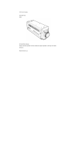
Note: The model and serial numbers of your product are important for you to keep for your convenience and
protection. These numbers appear on the nameplate located on the bottom of the product. Please record these
numbers in the spaces provided below, and retain this manual for future reference.
Model No. Serial No.
Hitachi Kokusai Electric Inc.

A
IMPORTANT SAFETY INSTRUCTIONS
1. Read Instructions
All the safety and operating instructions should
be read before the product is operated.
2. Retain Instructions
The safety and operating instructions should be
retained for future reference.
3. Heed Warnings
All warnings on the product and the operating
instructions should be adhered to.
4. Follow Instructions
All operating and use instructions should be
followed.
5. Cleaning
Unplug this product from the wall outlet before
cleaning. Do not use liquid cleaners or aerosol
cleaners. Use a damp cloth for cleaning.
6. Attachments
Do not use attachments not recommended by the
product manufacturer as they may cause
hazards.
7. Water and Moisture
Do not use this product near water - for example,
near a bath tub, wash bowl, kitchen sink, or
laundry tub; in a wet basement; or near a
swimming pool; and the like.
8. Accessories
Do not place this product on an unstable cart,
stand, tripod, bracket, or table. The product may
fall, causing serious injury to a child or adult, and
serious damage to the product. Use only with a
cart, stand, tripod, bracket, or table recommended
by the manufacturer, or sold with the product.
Any mounting of the product should follow the
manufacturer's instructions, and should use a
mounting accessory recommended by the
manufacturer.
9. Moving
A product and cart combination should be moved
with care.
Quick stops, excessive force, and uneven surfaces
may cause the product and cart combination to
overturn.
10. Ventilation
Slots and openings in the cabinet are provided for
ventilation and to ensure reliable operation of the
product and to protect it from overheating, and
these openings must not be blocked or covered.
The openings should never be blocked by placing
the product on a bed, sofa, rug, or other similar
surface. This product should not be placed in a

B
built-in installation such as a bookcase or rack
unless proper ventilation is provided or the
manufacturer's instructions have been adhered
to.
11. Power Sources
This product should be operated only from the
type of power source indicated on the marking
label. If you are not sure of the type of power
supply to your home, consult your product dealer
or local power company. For products intended
to operate from battery power, or other sources,
refer to the operating instructions.
12. Grounding or Polarization
This product is equipped with a three-wire
grounding-type plug a plug having a third
(grounding) pin. This plug will only fit into a
grounding-type power outlet. This is a safety
feature. If you are unable to insert the plug into
the outlet, contact your electrician to replace
your obsolete outlet. Do not defeat the safety
purpose of the grounding-type plug.
13. Power-Cord Protection
Power-supply cords should be routed to that they
are not likely to be walked on or pinched by items
placed upon or against them, paying particular
attention to cords at plug, convenience
receptacles, and the point where they exit from
the product.
14. Lightning
For added protection for this product during a
lightning storm, or when it is left unattended and
unused for long periods of time, unplug it from
the wall outlet. This will prevent damage to the
product due to lightning and power-line surges.
15. Overloading
Do not overload wall outlets, extension cords or
integral convenience receptacles as this can result
in a risk of fire or electric shock.
16. Object and Liquid Entry
Never push objects of any kind into this product
through openings as they may touch dangerous
voltage points or short-out parts that could result
in a fire or electric shock. Never spill liquid of
any kind on the product.
17. Inflammable and Explosive Substance
Avoid using this product where there are gases,
and also where there are inflammable and
explosive substances in the immediate vicinity.
18. Heavy Shock or Vibration
When carrying this product around, do not subject
the product to heavy shock or vibration.

C
19. Servicing
Do not attempt to service this product yourself as
opening or removing covers may expose you to
dangerous voltage or other hazards. Refer all
servicing to qualified service personnel.
20. Damage Requiring Service
Unplug this product from the wall outlet and
refer servicing to qualified service personnel
under the following conditions:
a.When the power-supply cord or plug is
damaged.
b.If liquid has been spilled, or objects have fallen
into the product.
c. If the product has been exposed to rain or
water.
d.If the product does not operate normally by
following the operating instructions. Adjust
only those controls that are covered by the
operating instructions as an improper
adjustment of other controls may result in
damage and will often require extensive work
by a qualified technician to restore the product
to its normal operation.
e. If the product has been dropped or damaged in
any way.
f. When the product exhibits a distinct change in
performance-this indicates a need for service.
21. Replacement Parts
When replacement parts are required, be sure the
service technician has used replacement parts
specified by the manufacturer or have the same
characteristics as the original part.
Unauthorized substitutions may result in fire,
electric shock, or other hazards.
22. Safety Check
Upon completion of any service or repairs to this
product, ask the service technician to perform
safety checks to determine that the product is in
proper operating condition.
23. Wall or Ceiling Mounting
The product should be mounted to a wall or
ceiling only as recommended by the
manufacturer.
24. Heat
The product should be situated away from heat
sources such as radiators, heat registers, stoves,
or other products (including amplifiers) that
produce heat
.

L
IMPORTANT NOTICE
These products have been tested and found to
comply with the limits for a Class A digital
device, pursuant to Part 15 of the FCC Rules.
These limits are designed to provide
reasonable protection against harmful
interference when the equipment is operated
in a commercial environment. This
equipment generates, uses, and can radiate
radio frequency energy and, if not installed
and used in accordance with the instruction
manual, may cause harmful interference to
radio communications. Operation of this
product in a residential area is likely to cause
harmful interference in which case the user
will be required to correct the interference at
his own expense.
WARNING
Changes or modifications not expressly
approved by Hitachi Denshi responsible for
compliance could void the user’s authority to
operate the equipment.
This product does not exceed the class A/class
B limits for radio noise emissions from digital
apparatus as set out in the radio interference
regulations.
Le présent appareil n’émet pas de bruits
radioélectriques dépassant les limités
applicable aux appareils numériques de classe
A prescrites dans le rVglement sur le
brouillage radioélectrique édicter par le
ministére des communications du canada.
For USA For Canada

M
Table of contents
IMPORTANT SAFETY INSTRUCTUIONS
・・
A
IMPORTANT NOTICE
・・・・・・・・・・・・・・・・・・・
L
Table of contents
・・・・・・・・・・・・・・・・・・・・・・・・・
M
Standard composition
・・・・・・・・・・・・・・・・・・・・・
1
Overview
・・・・・・・・・・・・・・・・・・・・・・・・・・・・・・・・
1
Features
・・・・・・・・・・・・・・・・・・・・・・・・・・・・・・・・・
2
Notes to users
・・・・・・・・・・・・・・・・・・・・・・・・・・・・
3
Important safety notes
・・・・・・・・・・・・・・・・・・・
3
Operating considerations
・・・・・・・・・・・・・・・・
3
CCD properties
・・・・・・・・・・・・・・・・・・・・・・・・・
4
Name and function each section
・・・・・・・・・・・・
5
LENS selection
・・・・・・・・・・・・・・・・・・・・・・・・・・・・
7
System example
・・・・・・・・・・・・・・・・・・・・・・・・・・・
8
Menu screen operation
・・・・・・・・・・・・・・・・・・・・・
9
Menu Structure
・・・・・・・・・・・・・・・・・・・・・・・・・
9
MAIN MENU
・・・・・・・・・・・・・・・・・・・・・・・・・・
14
SUB MENU 1
・・・・・・・・・・・・・・・・・・・・・・・・・・
15
SUB MENU 2
・・・・・・・・・・・・・・・・・・・・・・・・・・
18
ALC
・・・・・・・・・・・・・・・・・・・・・・・・・・・・・・・・・
20
SPECIAL SET
・・・・・・・・・・・・・・・・・・・・・・・・・
22
WHITE GATE
・・・・・・・・・・・・・・・・・・・・・・・・・
23
LEVEL
・・・・・・・・・・・・・・・・・・・・・・・・・・・・・・・・
24
MASKING
・・・・・・・・・・・・・・・・・・・・・・・・・・・・
25
GAMMA
・・・・・・・・・・・・・・・・・・・・・・・・・・・・・
26
DTL
・・・・・・・・・・・・・・・・・・・・・・・・・・・・・・・・・
27
DTL-SUB
・・・・・・・・・・・・・・・・・・・・・・・・・・・・
29
EXT TRIGGER
・・・・・・・・・・・・・・・・・・・・・・・
30
OUTPUT/SYNC
・・・・・・・・・・・・・・・・・・・・・・・・
35
FILE SET
・・・・・・・・・・・・・・・・・・・・・・・・・・・・
37
OTHER FUNC
・・・・・・・・・・・・・・・・・・・・・・・・
38
ID/TITLE
・・・・・・・・・・・・・・・・・・・・・・・・・・・・・・
40
How to Attain Better images
・・・・・・・・・・・・・・・
42
Black Balance Adjustment
・・・・・・・・・・・・・・
42
White Balance Adjustment
・・・・・・・・・・・・・・
43
Real time Auto White
・・・・・・・・・・・・・・・・・・・
45
Auto Shading Correction
・・・・・・・・・・・・・・・・
45
ALC (Auto level control)
・・・・・・・・・・・・・・・・
46
Long-Time Store Mode
・・・・・・・・・・・・・・・・・・
47
RC-Z3 remote control panel
・・・・・・・・・・・・・・・・
49
Function Selection by internal Switch Setting58
Connectors
・・・・・・・・・・・・・・・・・・・・・・・・・・・・・・・
59
Specifications
・・・・・・・・・・・・・・・・・・・・・・・・・・・・
62
Input/Output Signals
・・・・・・・・・・・・・・・・・・・・・
65
Major accessories
・・・・・・・・・・・・・・・・・・・・・・・・・
67
Dimensions
・・・・・・・・・・・・・・・・・・・・・・・・・・・・・・
67

1
Standard composition
Check when unpacking.
Camera, HV-D27A or HV-D37A
・・・・・・・・・・・・・・・・・・・・・・・・・・・・・・・
1
Camera cable 3m(10ft: C-301KAJ) or 10m(33ft: C-102KAJ)
Or 20m(66ft: C-202KAJ)
・・・・・・・・・・・・・・・・・・・・・・・・・・・・・・・・・・・・・
1
Power plug, R03-P3F (JPR0034*)
・・・・・・・・・・・・・・・・・・・・・・・・・・・・・・
1
Operation Manual
・・・・・・・・・・・・・・・・・・・・・・・・・・・・・・・・・・・・・・・・・・・・
1
* Part code
Overview
The HV-D27A and HV-D37A from Hitachi are
separate head and control unit type 3 CCD color
cameras respectively incorporating 1/2-inch and
1/3-inch 410,000 (470,000 in the PAL version) pixel
CCD image sensors. The circuit from processor to
encoder is digitized and contained on a single chip
to deliver top level picture quality and stability.
Hitachi's extensive experience in broadcast and
industrial color cameras has lead to an exclusive
14-bit digital processing technology that provides a
host of important functions in a newly developed
LSI device. The high quality signal processing
and image compensating functions were
unattainable in earlier analog cameras. The
versatile C mount also allows use with a broad
range of optical systems and opens up applications
in a wide variety of fields.

2
Features
Single chip LSI camera signal processor
Hitachi's leading edge processing technology
(0.18 um, internal core 1.8V drive, and 3 million
gates) is contained on a single newly developed
ultra LSI chip. The system is compact and
consumes very little power. Also, the 12-bit A/D
converter and 14-bit internal processor provide
high signal to noise ratio and wide dynamic
range.
C moot
The camera uses a C mount lens, which is the de
facto standard in the industry
Note : Some lenses cannot be used. Check
before use. See page 7 when using lens.
High quality picture
Three 410,000 pixel (470,000 PAL) CCDs with
high sensitivity microlenses are mated to prism
optics using high precision matching technology.
Accelerated digital luminance signal processing
is used to deliver a horizontal resolution of 800
TV lines with HV-D27A and 750 TV lines with
HV-D37A (luminance channel).
A new digital noise reduction system provides 62
dB (60dB PAL) with HV-D27A and 60dB (58dB
PAL) with HV-D37A signal to noise ratio. Clear
low noise images are obtained even in high gain
mode.
Auto shading compensation (ASC)
Color shading incurred when using a C mount
lens is automatically compensated (attenuated).
Two modes of shading are provided and can be
selected according to the cameras application, a
vertical color shading mode or a two-dimensional
luminance-shading mode.
Bi-directional data communication
The camera can be connected to a personal
computer via RS-232C for two-way data
communications to provide finely detailed
camera control. An identification (ID) code can
be assigned to each camera in a system and allow
remotely controlling multiple cameras from a
single computer.

3
Notes to users
Important safety notes
Use this camera with a 12 VDC power supply.
Observe that flammable objects, water or metal
do not enter the camera interior. These may
lead to failure or accident.
Do not modify the camera or use the camera with
external covers removed. These may cause
failure, void any warranties and pose a safety
hazard.
Stop using the camera at the approach of an
electrical storm (thunder audible). Protect the
camera from rain if using it outdoors.
In event the camera shows any abnormality,
switch off the camera and disconnect the power
cord. Contact a Hitachi Denshi service
representative.
Operating considerations
Power supply
Check that the supplied voltage is between 10.5
and 15 VDC. Inadequate voltage can affect
color fidelity and cause noise, while voltage over
15 V can damage the camera.
Connectors
Confirm the power is off before connecting or
disconnecting a signal cable. Grasp connectors
by the body, not the attached wires.
Lens
The correct lens is important for deriving
optimum performance from the camera.
Consult a Hitachi Denshi dealer for a selection of
fine lenses according to the application.
Installation and storage sites
The following types of environment can impair
performance, lead to damage, pose safety hazards
and shorten the useful life of the camera. Select
the sites for installing the storing the camera
carefully.
• Direct sunlight, rain or snow
• Flammable or corrosive gasses
• Very hot or cold (beyond -10 to 45 ℃
operating, -20 to 60 ℃ storage)
• Humid or dusty
• Exposed to vibration or shock
• Strong electrical or magnetic fields
• Exceptionally strong light
Continuous operation
In situations where the camera is used
continuously for long periods of time, the
ambient temperature should be kept below 40 ℃
in order to avoid accelerated deterioration of
internal parts and to derive maximum long-term
reliability.

4
Cleaning
A photographer’s blower or lens brush can be used
for clearing dust from the lens and optical filters.
Wipe dust from the case with a soft dry cloth. If
soiling is severe, moisten the cloth with a solution
of neutral detergent. Afterwards, wipe the cover
with a dry cloth.
Do not use petroleum distillates, alcohol or spray
type cleaners.
Transportation
Remove the lens (install lens mount cap) and other
attachments. Pack the camera carefully in its
original or equivalent container. Use ample
cushioning to protect the camera from physical
shock.
CCD properties
The following phenomena are inherent to a charge
coupled device imaging element and do not
indicate malfunction.
1) Smear and blooming
Vertical bands are visible when a strong light
enters the scene. Adjust the camera aiming
direction carefully to avoid strong direct or
reflected light.
2) Fixed pattern noise
High ambient temperature can cause fixed
pattern noise to appear throughout the scene.
3) Moire
Interaction between patterns can produce an
additional "phantom" pattern to appear. The
CCD picture elements (pixels) are arranged in a
pattern, which can interact with a pattern in
the scene (e.g., a performer wearing a finely
striped necktie) to result in a Moire pattern.
The effect should be considered when selecting
costumes, props and other scene elements.
4) Ghosting
Strong direct or reflected light near an object
of interest can cause ghosting of the object to
appear in the picture. The effect is more
obtrusive with certain iris settings and lens
types. Select the scene layout and camera
pointing direction carefully in order to avoid
this effect.

5
Name and function each section
AWB/L button
DERECT mode:
Holding down this button for more than
two seconds carries out auto white
balance(ALB).
MENU mode:
In this mode,it is allowed to change
functional data or carry out each function.
MENU button
Press this button to display the
camera setup menu. The switches
U,D,L and R provide different
functions depending on whether
the menu is displayed (MENU
mode) or not (DERECT mode).
U button
DERECT mode:Not available.
MENU MODE:
Pressing this button moves the
cursor up.
SCENE/R button
DERECT mode:
Selects the scene file.Press once to show the
present file name for 1 second.During the
display,press again to change the scene file.
MENU mode:
In this mode,it is allowed to change
functional data or carry out each function.
Pilot lamp
CAMERA connector
BAR/D button
DERECT mode:
Press this button to turn on/off a
color bar signal.
MENU mode:
Press this button to move the cursor
down.

6
VIDEO conector
Outputs a composite video
signal(1Vp-p/75 ohm).
REMOTE connector
Used for connection with
the remote control box
RC-C10 or personal
computer.
GL IN connector
Receives a black burst
signal or composite is
video signal where this
equipment operated
with external
synchronization.
12V IN connector
MULTI connector
Delivers an R/G/B,Y/R-Y/B-Y
or Y/C output signal and a
sync signal.
Y/C connector
Output an Y/C
signal.(S tarminal)
TRIG connector
External trigger signal input for field on
demand mode operation.Or,an HD/VD
signal is input where this equipment is
operated with external HD/VD
synchronization.
REMOTE
DC IN
+12V
GL S-VIDEO
VIDEO
MULTI
TRIG

7
Lens selection
(1) The proper lens is vital for obtaining full performance from the camera. The exit pupil distance is
particularly important for a 3 CCD type camera. If too short, vertical color shading can appear in the
picture.
(2) As the lens iris approaches fully open, problems such as loss of resolution, shading and flare (overall
image "white-out") can detract from picture quality.
(3) Image ghosting can occur if the lens is not matched to the CCD. Choose 1/2-inch for the HV-D27A
and 1/3-inch for HV-D37A.
(4) The camera dose not include flangeback adjustment. Depending on the type, focus might be
imperfect at the telephoto and wide angle extremes of a zoom lens.
Flange surface of lens
3.8mm or less (HV-D27A)
4.3mm or less (HV-D37A)
CAUTION:
Observe the dimensions of the lens
mounting selection as illustrated at
the right.
If the dimensions are not observed,
do not use such a lens, because the
lens and the camera will be damaged

8
System examples
AC adaptor
VBS
REMOTE
DC IN
R/R-Y/C
G/Y/Y
B/B-Y/VBS
SYNC
PC + Frame grabber
*RC-232C level converter
JU-C20
System power supply
Y/C
MULTI
VBS
Remote control box
RC-Z3
Color monitor
MICROSCOPE
* A level converter is required if controlling the
camera from a personal computer via RS-
232C interface over a distance more than 15
m.
JUNCTION BOX
JU-Z2
Max 8 cameras
Y/C
MULTI
Computer Image Processing & FA
HV-D27A / HV-D37A
CCU
HEAD
LENS
Camera cable
Standard C-301KAJ (3m)
Option C-102KAJ (10m)
Option C-202KAJ (20m)

9
Menu Screen Operation
1. Menu Structure
For settings in the camera, the MAIN and SPECIAL menus are available.
1-1 MAIN Menu Structure
Press the MENU button and MAIN MENU appears on the screen to indicate the main menu mode. Again
press the MENU button to extinguish the menu and enter the direct mode. There are a main function setup
menu and three sub-menus, which are arranged hierarchically as shown below. On the MAIN menu, bring
the cursor to SUB MENU 1, SUB MENU 2 or ALC and press the R button, and the desired subsidiary menu
will come up. To return to the MAIN MENU from the SUB menu 1, SUB menu 2 or ALC, bring the cursor to
the top line (title line of SUB MENU 1, SUB MENU 2 or ALC) and press the L button.
On each menu screen, bring the cursor to any desired item using the U or D button. For mode change/data
setting, use the L or R button.
■SUB MENU1
M. BLACK : 0
SHUTTER : VARIABLE
VARIABLE : 1/60.38
CCD MODE : FLD
D.N.R MODE : OFF
A.WHT SPEED : STANDARD
COMB FILTER : ON
FILE SELECT : FILE-1
■SUB MENU2
DYNA CHROMA : OFF
CHROMA GAIN : 0
MASKING : ON
GAMMA : ON
CONTRAST : OFF
KNEE : ON
SHADING MODE : LUMINANCE
AUTO SHADING :
AUTO BLACK :
FILE SELECT : FILE-1
■ALC
PEAK/AVE : 50/50
OVER RIDE : 0
SPEED : STANDARD
ALC GATE : OFF
ALC GATE SEL : PRESET1
FILE SELECT : FILE-1
■MAIN MENU
CAMERA MODE : MANUAL
WHITE BALANCE: PRESET 3200K
AGC : OFF
GAIN : 0dB
DTL : VARIABLE
VARIABLE : 0
SUB MENU1 : ->
SUB MENU2 : ->
ALC : ->
FILE SELECT :FILE-1

10
1-2 SPECIAL Menu Structure
To select the SPECIAL SET mode, press the MENU button for 2 seconds while holding down the U button.
Thus, the SPECIAL SET menu can be displayed. To return to the DIRECT mode, press the MENU button
again. The SPECIAL SET menu indicates a list of items, and each special items subsidiary menus are
available. These menus are arranged hierarchically as shown below. On the SPECIAL SET menu, most
items have '->' mark at the right side. For these items, press the R button, and the relevant item setup
menu will come up. To return to the SPECIAL SET menu, bring the cursor to the top line (title line of each
subsidiary menu) and press the L button.
On each menu screen, bring the cursor to any desired item using the U or D button. For mode change/data
setting, use the L or R button.

11
■DTL SUB(ON)
LEVEL DEP. : 0
CRISP : 0
H/V BALANCE : 0
INITIALIZE
■OUTPUT/ SYNC
OUTPUT : R,G,B
COLOR BAR : OFF
MONO : OFF
SYNC ON G : OFF
GL IN : 75ohm
GL MODE : VBS
SC COARSE : 0
°
SC FINE : 0
H PHASE : 0
■ID/TITLE
ID : OFF
TITLE : OFF
DATA SET : ->
■DATA SET
ID :
□□□
TITLE :□□□□□□□□ □□□□
1234567890_?
ABCDEFGHI JKL
MNOPQRSTUVWX
YZ()+-*/.,:;
<- -> DEL INS RET
■FILE SET
FILE SEL : FILE-1
STORE FILE : FILE-2
STORE :PUSH L&R 1SEC
STORE PRESET:PUSH L&R
1SEC
ALL INITIALIZE:
■OTHER FUNC
NEGA : OFF
FLARE : ON
FLARE LEVEL : 0
KNEE POINT : 0
WHITE CLIP : 0
MESSAGE RTN : ON
REMOTE : 9600bps
REMOTE TYPE :MODE2
ID/TITLE : ->
P.C : ON
■DTL( ON)
DTL FREQUENCY: STANDARD
HI CHROMA DTL : OFF
COLOR DTL :OFF
AUTO SETPU :
LEVEL : 0
PHASE : 0 R-Mg
WIDTH : 0
INITIALIZE :
FILE SELECT : FILE-1
DTL SUB : ->
■EXT TRIGGER
TRIGGER MODE : MODE1
DELAY TIME : 3H
TRIG POLARITY :
POSITIVE
WE POLARITY : POSITIVE
FILE SELECT : FILE-1
■G AMMA( ON)
GAMMA TABLE :
STANDARD
TOTAL GAMMA : 0
R GAMMA : 0
B GAMMA : 0
INITIALIZE :
FILE SELECT : FILE-1
■SPECIAL SET
WHITE GATE : ->
LEVEL : ->
MASKING : ->
GAMMA : ->
DTL : ->
EXT TRIGGER : ->
OUTPUT/SYNC: ->
FILE SET : ->
OTHER FUNC : ->
■LEVEL
ENABLE : ON
R GAIN : 0
B GAIN : 0
R BLACK : 0
B BLACK : 0
INITIALIZE
FILE SELECT:FILE-1
■WHITE GATE
GATE : OFF
GATE AREA(UP/DOWN)
GATE AREA(LEFT/RIGHT)
■MASKING
MASKING : ON
R HUE: 0 R SAT: 0
Y HUE: 0 Y SAT: 0
G HUE: 0 G SAT: 0
C HUE: 0 C SAT: 0
B HUE: 0 B SAT: 0
M HUE: 0 M SAT: 0
INITIALIZE
FILE SEL :FILE-1
SYNC/ HD OUT : OFF

12
Flashing
■MAIN MENU AUTO
CAMERA MODE : AUTO
*WHITE BALANCE : AUTO
*AGC : ON
AGC LIMIT : +20dB
DTL : VARIABLE
VARIABLE : 0
SUB MENU1 : ->
SUB MENU2 : ->
ALC : ->
FILE SELECT : FILE-1
2. MAIN MENU
1) CAM MODE : Camera mode
• MANUAL : Nearly all function modes can be set. Use for detailed settings.
•
AUTO : Video level and white balance are automatic and a standard picture cam be observed
without detailed settings.
Asterisk (*) indicates a fixed setting and the cursor jumps to the next item. The Auto indication flashes
when a function is related to the auto mode. At the Lens menu, the shutter mode changes according to
the Lens Type setting.
MENU Function and Mode
WHITE BALANCE : AUTO
A
GC
: ON
SUB MENU 1 SHUTTER
: AES
KNEE : AUTO KNEE
GAMMA : ON
R BLK : Disable
B BLK : Disable

13
2) WHITE BAL : White balance mode
•
PRST 3200K : The white balance condition is optimized at a color temperature of 3200K.
•
PRST 5600K : The white balance condition is optimized at a color temperature of 5600K.
•
MEM : White balance is automatically adjusted by the direct mode AWB button.
•
AUTO : The white balance condition is set through real time auto white balancing
(automatic tracking white balance).
The adjustment speed can be selected with A.WHITE SPEED of SUB MENU 1.
Note: In the Auto CAM mode, white balance is fixed at AUTO.
3) AGC : AGC ON/OFF
•
ON : Gain is adjusted automatically to compensate for scene brightness.
The adjustment range is set by Limit from +6 to +24 dB in 1 dB steps.
•
OFF : Gain is fixed and manually adjustable in 1 dB steps from 0 to +24 dB.
4) DTL
:
DTL level setup
•
OFF : DTL OFF
•
LOW : DTL level decrease and a picture become soft.
•
NORMAL : DTL level is standard.
•
HIGH : DTL level increase and a picture become sharp.
•
VARIABLE : DTL level is VARIABLE value under a line.
The DTL level can be set to in a range of -128 to 127. The degree of contour
correction increases in the positive value setting, and it decreases in the negative
value setting. For zero (0) setting, hold down both the L and R buttons for approx.
two seconds.

14
5) SUB MENU 1 : The SUB menu 1 is brought up.
6) SUB MENU 2 : The SUB menu 2 is brought up.
7) ALC : The ALC is brought up.
8) FILE SELECT : Select among scene files 1, 2, 3, 4 and PRESET
Camera setting data can be stored in four scene files.
To shoot several scenes with different shooting conditions, it is needed to change settings suitable for
each scene. To reduce such troublesome operations, various shooting conditions can be memorized
previously to scene files, and the conditions most suitable for a scene can be read and set.
There is a FILE SELECT item in the following menu. The function and operation are same. It can
memory each setting data of the following MENU as the scene file.
MAIN MENU
SUB MENU 1
SUB MENU 2
ALC
SPECIAL SET LEVEL
SPECIAL SET MASKING
SPECIAL SET GAMMA
SPECIAL SET DTL
SPECIAL SET EXT TRIGGER
/