Page is loading ...

OPERATING INSTRUCTIONS
Title
TOCOR700 UV (Ex)
TOCOR700
TOC Water Analyzer
Installation
Operation
Maintenance

2 TOCOR700 · Operating Instructions · 8011462 V4.1 · © SICK AG
Document Information
Document ID
Title: Operating Instructions TOCOR700
Order No.: 8011462
Version: 4.1
Release: 2013-01
Product
Product name: TOCOR700
Variants: TOCOR700 UV
TOCOR700 TH
TOCOR700 TH + 2nd reactor
Software: Version 1.10
In these Operating Instructions, the designation TOCOR700 means
that the information is applicable for all variants.
Manufacturer
SICK AG
Erwin-Sick-Str. 1 · 79183 Waldkirch · Germany
Phone: +49 7641 469-0
Fax: +49 7641 469-1149
E-mail: info.pa@sick.de
Place of Manufacture
SICK AG
Poppenbütteler Bogen 9b · 22399 Hamburg · Germany
Trademarks
Norprene and Tygon are trademarks of Saint-Gobain Performance
Plastics Corporation.
Viton is a trademark of DuPont Dow Elastomers.
Swagelok is a trademark of the Swagelok Company.
Other product names used in this Manual may also be trademarks
and are only used for identification purposes.
Guarantee Information
Specified product characteristics and technical data do not serve
as guarantee declarations.
© SICK AG. All rights reserved.
Glossary
FIA: Flow Indication Alarm; measured value to monitor the carrier
gas volume flow
Firmware: Internal software of the device; mostly stored in eras-
able storage modules (EEPROMs)
LED: Light emitting diode (small display lights)
NDIR: Non-dispersive infrared; designation for optical gas analysis
methods in the infrared spectral range
PC: Personal Computer
TC: Total Organic Carbon (total carbon content)
TIC: Total Inorganic Carbon (carbon content from inorganic sub-
stances)
TNB: Total Nitrogen Bound (total nitrogen content)
TOC: Total Organic Carbon (carbon content from organic sub-
stances)
VAC: Volt Alternating Current (AC voltage)
VDC: Volt Direct Current (DC voltage)

TOCOR700 · Operating Instructions · 8011462 V 4.1 · © SICK AG 3
Warning Symbols
Warning levels / Signal words
WARNING
Risk or hazardous situation which could result in severe personal
injury or death.
CAUTION
Hazard which could result in less severe or minor injuries and/or
material damage.
NOTICE
Indicates a hazard or unsafe practice which could result in property
damage.
Information Symbols
Hazard (general)
Hazard by voltage
Hazard in potentially explosive atmospheres
Hazard by explosive substances/mixtures
Hazard by corrosive substances
Hazard by poisonous substances
Hazard by unhealthy substances
Hazard by high temperature or hot surfaces
Hazard through ultraviolet radiation (UV light)
Hazard for the environment/nature/organic life
Information about the use in potentially explosive
atmospheres
Important technical information for this device
Important information on electrical or electronic func-
tions
Supplementary information
Link to information at another place
Nice to know

Contents
4 TOCOR700 Operating Instructions V4.1 8011462 © SICK AG
1 Important Information . . . . . . . . . . . . . . . . . . . . . . . . . . . . . . . . . . . . . . . . . . . . . . 13
1.1 Main hazards . . . . . . . . . . . . . . . . . . . . . . . . . . . . . . . . . . . . . . . . . . . . . . . . . . . . . . . . . . . . . . . 14
1.2 Important operating information . . . . . . . . . . . . . . . . . . . . . . . . . . . . . . . . . . . . . . . . . . . . . . 15
1.3 Intended use . . . . . . . . . . . . . . . . . . . . . . . . . . . . . . . . . . . . . . . . . . . . . . . . . . . . . . . . . . . . . . . 16
1.3.1 Device function. . . . . . . . . . . . . . . . . . . . . . . . . . . . . . . . . . . . . . . . . . . . . . . . . . . . . . . . . . . 16
1.3.2 Installation location . . . . . . . . . . . . . . . . . . . . . . . . . . . . . . . . . . . . . . . . . . . . . . . . . . . . . . . 16
1.3.3 Intended users (target group) . . . . . . . . . . . . . . . . . . . . . . . . . . . . . . . . . . . . . . . . . . . . . . 16
1.3.4 Application limitations. . . . . . . . . . . . . . . . . . . . . . . . . . . . . . . . . . . . . . . . . . . . . . . . . . . . . 17
1.4 Responsibility of user. . . . . . . . . . . . . . . . . . . . . . . . . . . . . . . . . . . . . . . . . . . . . . . . . . . . . . . . 18
1.5 Additional documents . . . . . . . . . . . . . . . . . . . . . . . . . . . . . . . . . . . . . . . . . . . . . . . . . . . . . . . 19
2 Product Description. . . . . . . . . . . . . . . . . . . . . . . . . . . . . . . . . . . . . . . . . . . . . . . . . . 21
2.1 Product identification. . . . . . . . . . . . . . . . . . . . . . . . . . . . . . . . . . . . . . . . . . . . . . . . . . . . . . . . 22
2.2 Know-how for the TOCOR700. . . . . . . . . . . . . . . . . . . . . . . . . . . . . . . . . . . . . . . . . . . . . . . . . 23
2.2.1 Measuring principle . . . . . . . . . . . . . . . . . . . . . . . . . . . . . . . . . . . . . . . . . . . . . . . . . . . . . . . 23
2.2.2 Measuring system . . . . . . . . . . . . . . . . . . . . . . . . . . . . . . . . . . . . . . . . . . . . . . . . . . . . . . . . 24
2.2.3 Special advantages . . . . . . . . . . . . . . . . . . . . . . . . . . . . . . . . . . . . . . . . . . . . . . . . . . . . . . . 25
2.3 Device variants . . . . . . . . . . . . . . . . . . . . . . . . . . . . . . . . . . . . . . . . . . . . . . . . . . . . . . . . . . . . . 26
2.3.1 Reactor variants . . . . . . . . . . . . . . . . . . . . . . . . . . . . . . . . . . . . . . . . . . . . . . . . . . . . . . . . . . 26
2.3.2 Individual device versions and documentation. . . . . . . . . . . . . . . . . . . . . . . . . . . . . . . 26
2.3.3 Versions for potentially explosive atmospheres . . . . . . . . . . . . . . . . . . . . . . . . . . . . . . 26
2.3.4 Additional equipment . . . . . . . . . . . . . . . . . . . . . . . . . . . . . . . . . . . . . . . . . . . . . . . . . . . . . 29
2.4 Device design. . . . . . . . . . . . . . . . . . . . . . . . . . . . . . . . . . . . . . . . . . . . . . . . . . . . . . . . . . . . . . . 30
2.4.1 TOCOR700 UV (standard housing). . . . . . . . . . . . . . . . . . . . . . . . . . . . . . . . . . . . . . . . . . 30
2.4.2 TOCOR700 TH (wall housing) . . . . . . . . . . . . . . . . . . . . . . . . . . . . . . . . . . . . . . . . . . . . . . 32
2.5 User Guide for the TOCOR700 . . . . . . . . . . . . . . . . . . . . . . . . . . . . . . . . . . . . . . . . . . . . . . . . 34
2.5.1 What must you do? . . . . . . . . . . . . . . . . . . . . . . . . . . . . . . . . . . . . . . . . . . . . . . . . . . . . . . . 34
2.5.2 What can you do in addition? . . . . . . . . . . . . . . . . . . . . . . . . . . . . . . . . . . . . . . . . . . . . . . 35
3 Mounting and Assembly . . . . . . . . . . . . . . . . . . . . . . . . . . . . . . . . . . . . . . . . . . . . 37
3.1 Delivery state . . . . . . . . . . . . . . . . . . . . . . . . . . . . . . . . . . . . . . . . . . . . . . . . . . . . . . . . . . . . . . . 38
3.1.1 Unpack and check . . . . . . . . . . . . . . . . . . . . . . . . . . . . . . . . . . . . . . . . . . . . . . . . . . . . . . . . 38
3.1.2 Accessories and spare material included in scope of delivery . . . . . . . . . . . . . . . . . 38
3.1.3 Components packed separately (TOCOR700 TH) . . . . . . . . . . . . . . . . . . . . . . . . . . . . . 39
3.2 Installation location . . . . . . . . . . . . . . . . . . . . . . . . . . . . . . . . . . . . . . . . . . . . . . . . . . . . . . . . . 40
3.3 Final device assembly . . . . . . . . . . . . . . . . . . . . . . . . . . . . . . . . . . . . . . . . . . . . . . . . . . . . . . . 41
3.3.1 Fill drain hoses (siphons) with water . . . . . . . . . . . . . . . . . . . . . . . . . . . . . . . . . . . . . . . . 41
3.3.2 Fill the CO
2
absorber . . . . . . . . . . . . . . . . . . . . . . . . . . . . . . . . . . . . . . . . . . . . . . . . . . . . . . 43
3.3.3 Fill the corrosion inhibitor filter. . . . . . . . . . . . . . . . . . . . . . . . . . . . . . . . . . . . . . . . . . . . . 44
3.3.4 Fill the activated charcoal filter (only for TOCOR700 UV) . . . . . . . . . . . . . . . . . . . . . . 45
3.3.5 Fit the pump hoses . . . . . . . . . . . . . . . . . . . . . . . . . . . . . . . . . . . . . . . . . . . . . . . . . . . . . . . 46
3.4 Installing the reagent container. . . . . . . . . . . . . . . . . . . . . . . . . . . . . . . . . . . . . . . . . . . . . . . 47
3.4.1 Position and connect the reagent container . . . . . . . . . . . . . . . . . . . . . . . . . . . . . . . . . 47
3.4.2 Mixing the reagent . . . . . . . . . . . . . . . . . . . . . . . . . . . . . . . . . . . . . . . . . . . . . . . . . . . . . . . . 47
3.5 Thermal reactor assembly (only for TOCOR700 TH) . . . . . . . . . . . . . . . . . . . . . . . . . . . . 50
3.5.1 Fill the reactor crucible . . . . . . . . . . . . . . . . . . . . . . . . . . . . . . . . . . . . . . . . . . . . . . . . . . . . 50
3.5.2 Align the reactor crucible . . . . . . . . . . . . . . . . . . . . . . . . . . . . . . . . . . . . . . . . . . . . . . . . . . 52
3.5.3 Assemble the thermal reactor. . . . . . . . . . . . . . . . . . . . . . . . . . . . . . . . . . . . . . . . . . . . . . 53
3.5.4 Connect the thermal reactor . . . . . . . . . . . . . . . . . . . . . . . . . . . . . . . . . . . . . . . . . . . . . . . 55
Contents

Contents
TOCOR700 Operating Instructions V4.1 8011462 © SICK AG 5
4 Installation . . . . . . . . . . . . . . . . . . . . . . . . . . . . . . . . . . . . . . . . . . . . . . . . . . . . . . . . . . . . . 57
4.1 Housing installation . . . . . . . . . . . . . . . . . . . . . . . . . . . . . . . . . . . . . . . . . . . . . . . . . . . . . . . . . 58
4.1.1 Dimensions . . . . . . . . . . . . . . . . . . . . . . . . . . . . . . . . . . . . . . . . . . . . . . . . . . . . . . . . . . . . . . 58
4.1.2 Mounting location, ambient conditions . . . . . . . . . . . . . . . . . . . . . . . . . . . . . . . . . . . . . . 58
4.2 Waste water drain . . . . . . . . . . . . . . . . . . . . . . . . . . . . . . . . . . . . . . . . . . . . . . . . . . . . . . . . . . . 59
4.3 Gas outlet . . . . . . . . . . . . . . . . . . . . . . . . . . . . . . . . . . . . . . . . . . . . . . . . . . . . . . . . . . . . . . . . . . 59
4.4 Liquid feed . . . . . . . . . . . . . . . . . . . . . . . . . . . . . . . . . . . . . . . . . . . . . . . . . . . . . . . . . . . . . . . . . 60
4.4.1 “Sample” connection . . . . . . . . . . . . . . . . . . . . . . . . . . . . . . . . . . . . . . . . . . . . . . . . . . . . . . 60
4.4.2 “Single sample” connection . . . . . . . . . . . . . . . . . . . . . . . . . . . . . . . . . . . . . . . . . . . . . . . . 61
4.4.3 “Zero solution”/“Test solution” connection . . . . . . . . . . . . . . . . . . . . . . . . . . . . . . . . . . 61
4.4.4 “Reagent” connection . . . . . . . . . . . . . . . . . . . . . . . . . . . . . . . . . . . . . . . . . . . . . . . . . . . . . 61
4.5 External carrier gas feed . . . . . . . . . . . . . . . . . . . . . . . . . . . . . . . . . . . . . . . . . . . . . . . . . . . . . 62
4.6 Compressed air feed for the back-flush filter . . . . . . . . . . . . . . . . . . . . . . . . . . . . . . . . . . . 62
4.7 Purge gas feed for the pressurized enclosure . . . . . . . . . . . . . . . . . . . . . . . . . . . . . . . . . . 63
4.8 Cable installation in potentially explosive atmospheres. . . . . . . . . . . . . . . . . . . . . . . . . . 63
4.9 Mains connection . . . . . . . . . . . . . . . . . . . . . . . . . . . . . . . . . . . . . . . . . . . . . . . . . . . . . . . . . . . 64
4.9.1 Safety information for mains connection . . . . . . . . . . . . . . . . . . . . . . . . . . . . . . . . . . . . 64
4.9.2 Connect the power cable . . . . . . . . . . . . . . . . . . . . . . . . . . . . . . . . . . . . . . . . . . . . . . . . . . 65
4.10 Signal connections . . . . . . . . . . . . . . . . . . . . . . . . . . . . . . . . . . . . . . . . . . . . . . . . . . . . . . . . . . 66
4.10.1 Position of signal connections . . . . . . . . . . . . . . . . . . . . . . . . . . . . . . . . . . . . . . . . . . . . . . 66
4.10.2 Plug-in connectors of gas analyzer connection terminals . . . . . . . . . . . . . . . . . . . . . . 66
4.10.3 Outputs for signal voltage (auxiliary voltage) . . . . . . . . . . . . . . . . . . . . . . . . . . . . . . . . . 67
4.11 Safety information on signal connections . . . . . . . . . . . . . . . . . . . . . . . . . . . . . . . . . . . . . . 68
4.11.1 Installation free of voltage . . . . . . . . . . . . . . . . . . . . . . . . . . . . . . . . . . . . . . . . . . . . . . . . . 68
4.11.2 Allowable load . . . . . . . . . . . . . . . . . . . . . . . . . . . . . . . . . . . . . . . . . . . . . . . . . . . . . . . . . . . 68
4.11.3 Signal voltages in potentially explosive atmospheres . . . . . . . . . . . . . . . . . . . . . . . . . 68
4.11.4 Suitable signal cables . . . . . . . . . . . . . . . . . . . . . . . . . . . . . . . . . . . . . . . . . . . . . . . . . . . . . 69
4.11.5 Protection against induced voltages . . . . . . . . . . . . . . . . . . . . . . . . . . . . . . . . . . . . . . . . 69
4.12 Measured value outputs . . . . . . . . . . . . . . . . . . . . . . . . . . . . . . . . . . . . . . . . . . . . . . . . . . . . . 70
4.13 Analog inputs . . . . . . . . . . . . . . . . . . . . . . . . . . . . . . . . . . . . . . . . . . . . . . . . . . . . . . . . . . . . . . . 71
4.14 Switching outputs . . . . . . . . . . . . . . . . . . . . . . . . . . . . . . . . . . . . . . . . . . . . . . . . . . . . . . . . . . . 72
4.14.1 Switching functions . . . . . . . . . . . . . . . . . . . . . . . . . . . . . . . . . . . . . . . . . . . . . . . . . . . . . . . 72
4.14.2 Electrical function . . . . . . . . . . . . . . . . . . . . . . . . . . . . . . . . . . . . . . . . . . . . . . . . . . . . . . . . . 72
4.14.3 Connection contacts on the gas analyzer . . . . . . . . . . . . . . . . . . . . . . . . . . . . . . . . . . . . 73
4.15 Control inputs . . . . . . . . . . . . . . . . . . . . . . . . . . . . . . . . . . . . . . . . . . . . . . . . . . . . . . . . . . . . . . . 75
4.15.1 Available control functions . . . . . . . . . . . . . . . . . . . . . . . . . . . . . . . . . . . . . . . . . . . . . . . . . 75
4.15.2 Electrical function . . . . . . . . . . . . . . . . . . . . . . . . . . . . . . . . . . . . . . . . . . . . . . . . . . . . . . . . . 75
4.16 Digital Interfaces . . . . . . . . . . . . . . . . . . . . . . . . . . . . . . . . . . . . . . . . . . . . . . . . . . . . . . . . . . . . 76
4.16.1 Function of the interfaces. . . . . . . . . . . . . . . . . . . . . . . . . . . . . . . . . . . . . . . . . . . . . . . . . . 76
4.16.2 Connecting the interfaces. . . . . . . . . . . . . . . . . . . . . . . . . . . . . . . . . . . . . . . . . . . . . . . . . . 76
5Start-up . . . . . . . . . . . . . . . . . . . . . . . . . . . . . . . . . . . . . . . . . . . . . . . . . . . . . . . . . . . . . . . . . 77
5.1 Main switch . . . . . . . . . . . . . . . . . . . . . . . . . . . . . . . . . . . . . . . . . . . . . . . . . . . . . . . . . . . . . . . . .78
5.2 Start-up procedure . . . . . . . . . . . . . . . . . . . . . . . . . . . . . . . . . . . . . . . . . . . . . . . . . . . . . . . . . . 78

Contents
6 TOCOR700 Operating Instructions V4.1 8011462 © SICK AG
6 Operation (General). . . . . . . . . . . . . . . . . . . . . . . . . . . . . . . . . . . . . . . . . . . . . . . . . . 81
6.1 LEDs on the gas analyzer . . . . . . . . . . . . . . . . . . . . . . . . . . . . . . . . . . . . . . . . . . . . . . . . . . . . 82
6.2 Status messages on the display . . . . . . . . . . . . . . . . . . . . . . . . . . . . . . . . . . . . . . . . . . . . . . 83
6.3 Principle of operation. . . . . . . . . . . . . . . . . . . . . . . . . . . . . . . . . . . . . . . . . . . . . . . . . . . . . . . . 83
6.3.1 Function selection . . . . . . . . . . . . . . . . . . . . . . . . . . . . . . . . . . . . . . . . . . . . . . . . . . . . . . . . 83
6.3.2 Display of menu functions (example) . . . . . . . . . . . . . . . . . . . . . . . . . . . . . . . . . . . . . . . 83
6.3.3 Function keys . . . . . . . . . . . . . . . . . . . . . . . . . . . . . . . . . . . . . . . . . . . . . . . . . . . . . . . . . . . . 84
6.3.4 Menu levels . . . . . . . . . . . . . . . . . . . . . . . . . . . . . . . . . . . . . . . . . . . . . . . . . . . . . . . . . . . . . . 85
6.4 Selection switch for thermal reactors . . . . . . . . . . . . . . . . . . . . . . . . . . . . . . . . . . . . . . . . . 86
7 Standard Menu Functions. . . . . . . . . . . . . . . . . . . . . . . . . . . . . . . . . . . . . . . . . . 87
7.1 Main menu . . . . . . . . . . . . . . . . . . . . . . . . . . . . . . . . . . . . . . . . . . . . . . . . . . . . . . . . . . . . . . . . 88
7.2 Measuring displays. . . . . . . . . . . . . . . . . . . . . . . . . . . . . . . . . . . . . . . . . . . . . . . . . . . . . . . . . . 89
7.2.1 Compact representation of measured values . . . . . . . . . . . . . . . . . . . . . . . . . . . . . . . . 89
7.2.2 Large measured value display . . . . . . . . . . . . . . . . . . . . . . . . . . . . . . . . . . . . . . . . . . . . . 90
7.2.3 Chart recorder simulation . . . . . . . . . . . . . . . . . . . . . . . . . . . . . . . . . . . . . . . . . . . . . . . . . 90
7.3 Status displays . . . . . . . . . . . . . . . . . . . . . . . . . . . . . . . . . . . . . . . . . . . . . . . . . . . . . . . . . . . . . 92
7.3.1 Display status/fault messages . . . . . . . . . . . . . . . . . . . . . . . . . . . . . . . . . . . . . . . . . . . . . 92
7.3.2 Display measuring ranges . . . . . . . . . . . . . . . . . . . . . . . . . . . . . . . . . . . . . . . . . . . . . . . . . 92
7.3.3 Display measured value outputs . . . . . . . . . . . . . . . . . . . . . . . . . . . . . . . . . . . . . . . . . . . 93
7.3.4 Display alarm limit values . . . . . . . . . . . . . . . . . . . . . . . . . . . . . . . . . . . . . . . . . . . . . . . . . 93
7.3.5 Display instrument data . . . . . . . . . . . . . . . . . . . . . . . . . . . . . . . . . . . . . . . . . . . . . . . . . . . 94
7.3.6 Display drift values . . . . . . . . . . . . . . . . . . . . . . . . . . . . . . . . . . . . . . . . . . . . . . . . . . . . . . . 95
7.4 Control . . . . . . . . . . . . . . . . . . . . . . . . . . . . . . . . . . . . . . . . . . . . . . . . . . . . . . . . . . . . . . . . . . . . . 96
7.4.1 Switching the gas pump on/off. . . . . . . . . . . . . . . . . . . . . . . . . . . . . . . . . . . . . . . . . . . . . 96
7.4.2 Acknowledging alarms . . . . . . . . . . . . . . . . . . . . . . . . . . . . . . . . . . . . . . . . . . . . . . . . . . . . 97
7.4.3 Setting the display contrast . . . . . . . . . . . . . . . . . . . . . . . . . . . . . . . . . . . . . . . . . . . . . . . . 98
7.4.4 Setting the keypad click . . . . . . . . . . . . . . . . . . . . . . . . . . . . . . . . . . . . . . . . . . . . . . . . . . . 98
7.4.5 Switching reactor(s) on/off . . . . . . . . . . . . . . . . . . . . . . . . . . . . . . . . . . . . . . . . . . . . . . . . 99
7.4.6 Switching the dosing pump on/off . . . . . . . . . . . . . . . . . . . . . . . . . . . . . . . . . . . . . . . . . . 99
7.4.7 Switching the pre-sampling pump on/off (dosing pump M11) . . . . . . . . . . . . . . . . 100
7.4.8 Switching single sample on/off . . . . . . . . . . . . . . . . . . . . . . . . . . . . . . . . . . . . . . . . . . . 100
7.4.9 Switching dilution on/off (information) . . . . . . . . . . . . . . . . . . . . . . . . . . . . . . . . . . . . . 100
7.5 Calibration (information) . . . . . . . . . . . . . . . . . . . . . . . . . . . . . . . . . . . . . . . . . . . . . . . . . . . . 101
7.6 Maintenance signal . . . . . . . . . . . . . . . . . . . . . . . . . . . . . . . . . . . . . . . . . . . . . . . . . . . . . . . . 101
8 Expert Menu Functions. . . . . . . . . . . . . . . . . . . . . . . . . . . . . . . . . . . . . . . . . . . . . 103
8.1 Access to expert functions . . . . . . . . . . . . . . . . . . . . . . . . . . . . . . . . . . . . . . . . . . . . . . . . . . 104
8.2 Hidden expert functions . . . . . . . . . . . . . . . . . . . . . . . . . . . . . . . . . . . . . . . . . . . . . . . . . . . . 104
8.3 Local adaptation (localization). . . . . . . . . . . . . . . . . . . . . . . . . . . . . . . . . . . . . . . . . . . . . . . 105
8.3.1 Language . . . . . . . . . . . . . . . . . . . . . . . . . . . . . . . . . . . . . . . . . . . . . . . . . . . . . . . . . . . . . . . 105
8.3.2 Clock settings . . . . . . . . . . . . . . . . . . . . . . . . . . . . . . . . . . . . . . . . . . . . . . . . . . . . . . . . . . . 105
8.4 Measured values display. . . . . . . . . . . . . . . . . . . . . . . . . . . . . . . . . . . . . . . . . . . . . . . . . . . . 106
8.4.1 Number of decimal places . . . . . . . . . . . . . . . . . . . . . . . . . . . . . . . . . . . . . . . . . . . . . . . . 106
8.4.2 Bargraph range. . . . . . . . . . . . . . . . . . . . . . . . . . . . . . . . . . . . . . . . . . . . . . . . . . . . . . . . . . 106
8.5 Influencing measured values . . . . . . . . . . . . . . . . . . . . . . . . . . . . . . . . . . . . . . . . . . . . . . . . 107
8.5.1 Damping (floating average computation) . . . . . . . . . . . . . . . . . . . . . . . . . . . . . . . . . . . 107
8.5.2 Dynamic damping . . . . . . . . . . . . . . . . . . . . . . . . . . . . . . . . . . . . . . . . . . . . . . . . . . . . . . . 108
8.5.3 Measured value suppression at the start of the measuring range . . . . . . . . . . . . 109

Contents
TOCOR700 Operating Instructions V4.1 8011462 © SICK AG 7
8.6 Monitoring measured values . . . . . . . . . . . . . . . . . . . . . . . . . . . . . . . . . . . . . . . . . . . . . . . .110
8.6.1 Alarm limit values . . . . . . . . . . . . . . . . . . . . . . . . . . . . . . . . . . . . . . . . . . . . . . . . . . . . . . . .110
8.6.2 Overflow warnings. . . . . . . . . . . . . . . . . . . . . . . . . . . . . . . . . . . . . . . . . . . . . . . . . . . . . . . .111
8.7 Configuration of calibrations (information) . . . . . . . . . . . . . . . . . . . . . . . . . . . . . . . . . . . .111
8.8 Configuration of measured value outputs . . . . . . . . . . . . . . . . . . . . . . . . . . . . . . . . . . . .112
8.8.1 Special function with the “Sample point selector” option. . . . . . . . . . . . . . . . . . . . .112
8.8.2 Assigning measured value outputs. . . . . . . . . . . . . . . . . . . . . . . . . . . . . . . . . . . . . . . . .112
8.8.3 Configuring output ranges . . . . . . . . . . . . . . . . . . . . . . . . . . . . . . . . . . . . . . . . . . . . . . . .113
8.8.4 Displaying of output ranges . . . . . . . . . . . . . . . . . . . . . . . . . . . . . . . . . . . . . . . . . . . . . . .114
8.8.5 Selecting output ranges . . . . . . . . . . . . . . . . . . . . . . . . . . . . . . . . . . . . . . . . . . . . . . . . . .114
8.8.6 Setting live zero/deactivating a measured value output. . . . . . . . . . . . . . . . . . . . . .115
8.8.7 Selecting the output mode during calibration . . . . . . . . . . . . . . . . . . . . . . . . . . . . . . .115
8.8.8 Deleting the settings for a measured value output . . . . . . . . . . . . . . . . . . . . . . . . . .116
8.9 Configuration of switching outputs . . . . . . . . . . . . . . . . . . . . . . . . . . . . . . . . . . . . . . . . . . .117
8.9.1 Functional principle . . . . . . . . . . . . . . . . . . . . . . . . . . . . . . . . . . . . . . . . . . . . . . . . . . . . . .117
8.9.2 Control logic . . . . . . . . . . . . . . . . . . . . . . . . . . . . . . . . . . . . . . . . . . . . . . . . . . . . . . . . . . . . .117
8.9.3 Safety criteria . . . . . . . . . . . . . . . . . . . . . . . . . . . . . . . . . . . . . . . . . . . . . . . . . . . . . . . . . . .117
8.9.4 Available switching functions (overview & explanation) . . . . . . . . . . . . . . . . . . . . . .118
8.9.5 Assigning switching functions . . . . . . . . . . . . . . . . . . . . . . . . . . . . . . . . . . . . . . . . . . . . .119
8.10 Configuration of status and control inputs . . . . . . . . . . . . . . . . . . . . . . . . . . . . . . . . . . . .120
8.10.1 Functional principle . . . . . . . . . . . . . . . . . . . . . . . . . . . . . . . . . . . . . . . . . . . . . . . . . . . . . .120
8.10.2 Available control functions (overview & explanation). . . . . . . . . . . . . . . . . . . . . . . . .120
8.10.3 Assigning control functions . . . . . . . . . . . . . . . . . . . . . . . . . . . . . . . . . . . . . . . . . . . . . . .121
8.10.4 Digital interface parameters . . . . . . . . . . . . . . . . . . . . . . . . . . . . . . . . . . . . . . . . . . . . . .122
8.10.5 Automatic digital output of measured data . . . . . . . . . . . . . . . . . . . . . . . . . . . . . . . . .123
8.10.6 Printing configuration data (output as text table) . . . . . . . . . . . . . . . . . . . . . . . . . . . .125
8.11 Digital remote control (settings) . . . . . . . . . . . . . . . . . . . . . . . . . . . . . . . . . . . . . . . . . . . . .126
8.11.1 Setting the ID character . . . . . . . . . . . . . . . . . . . . . . . . . . . . . . . . . . . . . . . . . . . . . . . . . . 126
8.11.2 Activating the ID character / activating Modbus . . . . . . . . . . . . . . . . . . . . . . . . . . . . .127
8.11.3 Setting the installed connection . . . . . . . . . . . . . . . . . . . . . . . . . . . . . . . . . . . . . . . . . . .127
8.11.4 Configuring the modem connection . . . . . . . . . . . . . . . . . . . . . . . . . . . . . . . . . . . . . . . .128
8.11.5 Modem control . . . . . . . . . . . . . . . . . . . . . . . . . . . . . . . . . . . . . . . . . . . . . . . . . . . . . . . . . . 129
8.12 Data backup
. . . . . . . . . . . . . . . . . . . . . . . . . . . . . . . . . . . . . . . . . . . . . . . . . . . . . . . . . . . . . . .130
8.12.1 Internal backup (saving the settings). . . . . . . . . . . . . . . . . . . . . . . . . . . . . . . . . . . . . . .130
8.12.2 External backup (data transmission) . . . . . . . . . . . . . . . . . . . . . . . . . . . . . . . . . . . . . . .131
8.13 Firmware update . . . . . . . . . . . . . . . . . . . . . . . . . . . . . . . . . . . . . . . . . . . . . . . . . . . . . . . . . . .134
8.14 Volume flow adjustment and monitoring . . . . . . . . . . . . . . . . . . . . . . . . . . . . . . . . . . . . . .135
8.14.1 Pump capacity (information) . . . . . . . . . . . . . . . . . . . . . . . . . . . . . . . . . . . . . . . . . . . . . .135
8.14.2 Flow limit value (information). . . . . . . . . . . . . . . . . . . . . . . . . . . . . . . . . . . . . . . . . . . . . .135
8.14.3 FIA limit value . . . . . . . . . . . . . . . . . . . . . . . . . . . . . . . . . . . . . . . . . . . . . . . . . . . . . . . . . . .136
8.14.4 Carrier gas volume flow. . . . . . . . . . . . . . . . . . . . . . . . . . . . . . . . . . . . . . . . . . . . . . . . . . .136
8.15 TOCOR parameters . . . . . . . . . . . . . . . . . . . . . . . . . . . . . . . . . . . . . . . . . . . . . . . . . . . . . . . . .137
8.15.1 Back-flush filter settings (option) . . . . . . . . . . . . . . . . . . . . . . . . . . . . . . . . . . . . . . . . . .137
8.15.2 Dilution factor (information) . . . . . . . . . . . . . . . . . . . . . . . . . . . . . . . . . . . . . . . . . . . . . . .137
8.15.3 Sample water limit value. . . . . . . . . . . . . . . . . . . . . . . . . . . . . . . . . . . . . . . . . . . . . . . . . .137
8.15.4 Semi-continuous mode(information) . . . . . . . . . . . . . . . . . . . . . . . . . . . . . . . . . . . . . . . 137

Contents
8 TOCOR700 Operating Instructions V4.1 8011462 © SICK AG
8.16 Control functions of the gas analyzer. . . . . . . . . . . . . . . . . . . . . . . . . . . . . . . . . . . . . . . . . 138
8.16.1 Measurement signals for measurement components. . . . . . . . . . . . . . . . . . . . . . . . 138
8.16.2 Status of internal controllers. . . . . . . . . . . . . . . . . . . . . . . . . . . . . . . . . . . . . . . . . . . . . . 139
8.16.3 Displaying internal analog signals . . . . . . . . . . . . . . . . . . . . . . . . . . . . . . . . . . . . . . . . . 139
8.16.4 Internal supply voltages . . . . . . . . . . . . . . . . . . . . . . . . . . . . . . . . . . . . . . . . . . . . . . . . . . 140
8.16.5 Service display of internal analog signals . . . . . . . . . . . . . . . . . . . . . . . . . . . . . . . . . . 140
8.16.6 Linearization values. . . . . . . . . . . . . . . . . . . . . . . . . . . . . . . . . . . . . . . . . . . . . . . . . . . . . . 141
8.16.7 Status of control inputs . . . . . . . . . . . . . . . . . . . . . . . . . . . . . . . . . . . . . . . . . . . . . . . . . . 141
8.16.8 Program version . . . . . . . . . . . . . . . . . . . . . . . . . . . . . . . . . . . . . . . . . . . . . . . . . . . . . . . . . 141
8.17 Sample point selector (option). . . . . . . . . . . . . . . . . . . . . . . . . . . . . . . . . . . . . . . . . . . . . . . 142
8.17.1 Function of the sample point selector. . . . . . . . . . . . . . . . . . . . . . . . . . . . . . . . . . . . . . 142
8.17.2 Sample point selection results . . . . . . . . . . . . . . . . . . . . . . . . . . . . . . . . . . . . . . . . . . . 142
8.17.3 Configuration of the sample point selector . . . . . . . . . . . . . . . . . . . . . . . . . . . . . . . . . 143
8.18 Testing electronic outputs (hardware test) . . . . . . . . . . . . . . . . . . . . . . . . . . . . . . . . . . . . 144
8.19 Reset . . . . . . . . . . . . . . . . . . . . . . . . . . . . . . . . . . . . . . . . . . . . . . . . . . . . . . . . . . . . . . . . . . . . . 145
9Calibration . . . . . . . . . . . . . . . . . . . . . . . . . . . . . . . . . . . . . . . . . . . . . . . . . . . . . . . . . . . . 147
9.1 Basic calibration information . . . . . . . . . . . . . . . . . . . . . . . . . . . . . . . . . . . . . . . . . . . . . . . . 148
9.1.1 Why is calibration necessary?. . . . . . . . . . . . . . . . . . . . . . . . . . . . . . . . . . . . . . . . . . . . . 148
9.1.2 How does a calibration procedure in the TOCOR700 basically work? . . . . . . . . . . 148
9.1.3 Alternative calibration procedures . . . . . . . . . . . . . . . . . . . . . . . . . . . . . . . . . . . . . . . . . 149
9.1.4 Alternative methods for zero point calibration . . . . . . . . . . . . . . . . . . . . . . . . . . . . . . 149
9.1.5 When is it necessary to perform a calibration?. . . . . . . . . . . . . . . . . . . . . . . . . . . . . . 149
9.1.6 Calibration liquid notation in the menus . . . . . . . . . . . . . . . . . . . . . . . . . . . . . . . . . . . 149
9.2 Calibration liquids . . . . . . . . . . . . . . . . . . . . . . . . . . . . . . . . . . . . . . . . . . . . . . . . . . . . . . . . . . 150
9.2.1 Zero water . . . . . . . . . . . . . . . . . . . . . . . . . . . . . . . . . . . . . . . . . . . . . . . . . . . . . . . . . . . . . . 150
9.2.2 Calibration solution . . . . . . . . . . . . . . . . . . . . . . . . . . . . . . . . . . . . . . . . . . . . . . . . . . . . . . 150
9.2.3 Stock solution . . . . . . . . . . . . . . . . . . . . . . . . . . . . . . . . . . . . . . . . . . . . . . . . . . . . . . . . . . . 151
9.3 Calibration preparation . . . . . . . . . . . . . . . . . . . . . . . . . . . . . . . . . . . . . . . . . . . . . . . . . . . . . 152
9.4 Manual calibration . . . . . . . . . . . . . . . . . . . . . . . . . . . . . . . . . . . . . . . . . . . . . . . . . . . . . . . . . 153
9.4.1 Manual calibration procedure . . . . . . . . . . . . . . . . . . . . . . . . . . . . . . . . . . . . . . . . . . . . . 153
9.5 Automatic calibration . . . . . . . . . . . . . . . . . . . . . . . . . . . . . . . . . . . . . . . . . . . . . . . . . . . . . . . 156
9.5.1 Requirements for automatic calibration (overview) . . . . . . . . . . . . . . . . . . . . . . . . . . 156
9.5.2 Different automatic calibration routines. . . . . . . . . . . . . . . . . . . . . . . . . . . . . . . . . . . . 156
9.5.3 Setting-up an automatic calibration . . . . . . . . . . . . . . . . . . . . . . . . . . . . . . . . . . . . . . . 157
9.5.4 Setting nominal values for calibration liquids . . . . . . . . . . . . . . . . . . . . . . . . . . . . . . . 158
9.5.5 Setting drift limit values . . . . . . . . . . . . . . . . . . . . . . . . . . . . . . . . . . . . . . . . . . . . . . . . . . 159
9.5.6 Ignoring an external calibration signal . . . . . . . . . . . . . . . . . . . . . . . . . . . . . . . . . . . . . 160
9.5.7 Setting a span delay time. . . . . . . . . . . . . . . . . . . . . . . . . . . . . . . . . . . . . . . . . . . . . . . . . 160
9.5.8 Setting the calibration measuring time. . . . . . . . . . . . . . . . . . . . . . . . . . . . . . . . . . . . . 161
9.5.9 Displaying automatic calibration settings . . . . . . . . . . . . . . . . . . . . . . . . . . . . . . . . . . 162
9.5.10 Starting the automatic calibration procedure manually . . . . . . . . . . . . . . . . . . . . . . 163
9.6 Displaying calibration data . . . . . . . . . . . . . . . . . . . . . . . . . . . . . . . . . . . . . . . . . . . . . . . . . . 164
9.7 Drift reset . . . . . . . . . . . . . . . . . . . . . . . . . . . . . . . . . . . . . . . . . . . . . . . . . . . . . . . . . . . . . . . . . 165
9.8 Special calibrations . . . . . . . . . . . . . . . . . . . . . . . . . . . . . . . . . . . . . . . . . . . . . . . . . . . . . . . . 166
9.8.1 Basic settings for measuring sensitivity . . . . . . . . . . . . . . . . . . . . . . . . . . . . . . . . . . . . 166
9.8.2 Basic gas analyzer calibration . . . . . . . . . . . . . . . . . . . . . . . . . . . . . . . . . . . . . . . . . . . . 167

Contents
TOCOR700 Operating Instructions V4.1 8011462 © SICK AG 9
10 Remote Control with MARC2000 . . . . . . . . . . . . . . . . . . . . . . . . . . . . . . . .171
10.1 Introduction to remote control with MARC2000. . . . . . . . . . . . . . . . . . . . . . . . . . . . . . . .172
10.2 Remote control installation . . . . . . . . . . . . . . . . . . . . . . . . . . . . . . . . . . . . . . . . . . . . . . . . . .173
10.2.1 Electrical connection . . . . . . . . . . . . . . . . . . . . . . . . . . . . . . . . . . . . . . . . . . . . . . . . . . . . .173
10.2.2 Making the necessary settings in the TOCOR700. . . . . . . . . . . . . . . . . . . . . . . . . . . .176
10.2.3 Setting the PC for remote control . . . . . . . . . . . . . . . . . . . . . . . . . . . . . . . . . . . . . . . . . .176
10.3 Starting and ending remote control operation . . . . . . . . . . . . . . . . . . . . . . . . . . . . . . . . .177
10.3.1 Starting remote control . . . . . . . . . . . . . . . . . . . . . . . . . . . . . . . . . . . . . . . . . . . . . . . . . . .177
10.3.2 Status message during remote control with MARC2000 . . . . . . . . . . . . . . . . . . . . .177
10.3.3 Ending remote control . . . . . . . . . . . . . . . . . . . . . . . . . . . . . . . . . . . . . . . . . . . . . . . . . . . .178
10.4 Remote control with “AK protocol” (information) . . . . . . . . . . . . . . . . . . . . . . . . . . . . . . .178
11 Remote Control with Modbus. . . . . . . . . . . . . . . . . . . . . . . . . . . . . . . . . . . . .179
11.1 Introduction to the Modbus protocol. . . . . . . . . . . . . . . . . . . . . . . . . . . . . . . . . . . . . . . . . . 180
11.2 Modbus specifications for the TOCOR700. . . . . . . . . . . . . . . . . . . . . . . . . . . . . . . . . . . . .181
11.3 Installing a Modbus remote control. . . . . . . . . . . . . . . . . . . . . . . . . . . . . . . . . . . . . . . . . . .182
11.3.1 Interface . . . . . . . . . . . . . . . . . . . . . . . . . . . . . . . . . . . . . . . . . . . . . . . . . . . . . . . . . . . . . . . .182
11.3.2 Electrical connection . . . . . . . . . . . . . . . . . . . . . . . . . . . . . . . . . . . . . . . . . . . . . . . . . . . . .182
11.3.3 Making the necessary settings on the TOCOR700 . . . . . . . . . . . . . . . . . . . . . . . . . . .182
11.4 Modbus function commands for the TOCOR700 . . . . . . . . . . . . . . . . . . . . . . . . . . . . . . .183
11.4.1 Function codes . . . . . . . . . . . . . . . . . . . . . . . . . . . . . . . . . . . . . . . . . . . . . . . . . . . . . . . . . .183
11.4.2 Data formats . . . . . . . . . . . . . . . . . . . . . . . . . . . . . . . . . . . . . . . . . . . . . . . . . . . . . . . . . . . .184
11.4.3 Modbus control commands . . . . . . . . . . . . . . . . . . . . . . . . . . . . . . . . . . . . . . . . . . . . . . .185
11.4.4 Modbus read commands . . . . . . . . . . . . . . . . . . . . . . . . . . . . . . . . . . . . . . . . . . . . . . . . .186
12 Maintenance. . . . . . . . . . . . . . . . . . . . . . . . . . . . . . . . . . . . . . . . . . . . . . . . . . . . . . . . . .189
12.1 Scheduled maintenance . . . . . . . . . . . . . . . . . . . . . . . . . . . . . . . . . . . . . . . . . . . . . . . . . . . .190
12.1.1 Maintenance plan . . . . . . . . . . . . . . . . . . . . . . . . . . . . . . . . . . . . . . . . . . . . . . . . . . . . .190
12.1.2 Maintenance protocol . . . . . . . . . . . . . . . . . . . . . . . . . . . . . . . . . . . . . . . . . . . . . . . . . . .191
12.2 Replacing expendable materials . . . . . . . . . . . . . . . . . . . . . . . . . . . . . . . . . . . . . . . . . . . . .192
12.2.1 Topping up reagent container . . . . . . . . . . . . . . . . . . . . . . . . . . . . . . . . . . . . . . . . . . . . .192
12.2.2 Replacing CO
2
absorption material . . . . . . . . . . . . . . . . . . . . . . . . . . . . . . . . . . . . . . . .193
12.2.3 Replacing the corrosion inhibitor filter. . . . . . . . . . . . . . . . . . . . . . . . . . . . . . . . . . . . . .195
12.2.4 Replacing the activated charcoal filter . . . . . . . . . . . . . . . . . . . . . . . . . . . . . . . . . . . . .196
12.2.5 Replacing dosing pump hoses (5 channel hose pump) . . . . . . . . . . . . . . . . . . . . . . .197
12.2.6 Replacing pre-sampling pump hoses (1 channel hose pump) . . . . . . . . . . . . . . . . .198
12.3 Cleaning the UV reactor (TOCOR700 UV) . . . . . . . . . . . . . . . . . . . . . . . . . . . . . . . . . . . . . .199
12.4 Maintenance work on the thermal reactor (TOCOR700 TH) . . . . . . . . . . . . . . . . . . . . .201
12.4.1 Safety information on the thermal reactor . . . . . . . . . . . . . . . . . . . . . . . . . . . . . . . .201
12.4.2 Cleaning the reactor on a TOCOR700 TH (1 reactor) . . . . . . . . . . . . . . . . . . . . . . . . .202
12.4.3 Cleaning the reactor on TOCOR700 TH + 2nd reactor . . . . . . . . . . . . . . . . . . . . . . . .203
12.5 Cleaning the waters lines. . . . . . . . . . . . . . . . . . . . . . . . . . . . . . . . . . . . . . . . . . . . . . . . . . . .204
12.6 Preventive maintenance measures. . . . . . . . . . . . . . . . . . . . . . . . . . . . . . . . . . . . . . . . . . .205
12.6.1 Replacing the filter pads of the housing . . . . . . . . . . . . . . . . . . . . . . . . . . . . . . . . . . . .205
12.6.2 Testing electrical signals. . . . . . . . . . . . . . . . . . . . . . . . . . . . . . . . . . . . . . . . . . . . . . . . . .205
12.6.3 Care of the housing . . . . . . . . . . . . . . . . . . . . . . . . . . . . . . . . . . . . . . . . . . . . . . . . . . . . . .205
12.6.4 Annual maintenance work by Customer Service . . . . . . . . . . . . . . . . . . . . . . . . . . . . .206

Contents
10 TOCOR700 Operating Instructions V4.1 8011462 © SICK AG
13 Troubleshooting . . . . . . . . . . . . . . . . . . . . . . . . . . . . . . . . . . . . . . . . . . . . . . . . . . . . . 207
13.1 How the TOCOR700 signals a malfunction … . . . . . . . . . . . . . . . . . . . . . . . . . . . . . . . . . 208
13.1.1 Signs of a malfunction . . . . . . . . . . . . . . . . . . . . . . . . . . . . . . . . . . . . . . . . . . . . . . . . . . . 208
13.1.2 Malfunction messages . . . . . . . . . . . . . . . . . . . . . . . . . . . . . . . . . . . . . . . . . . . . . . . . . . . 208
13.1.3 Safety information on malfunction clearance . . . . . . . . . . . . . . . . . . . . . . . . . . . . . 208
13.1.4 Support by Customer Service . . . . . . . . . . . . . . . . . . . . . . . . . . . . . . . . . . . . . . . . . . . . . 208
13.2 General operational malfunctions. . . . . . . . . . . . . . . . . . . . . . . . . . . . . . . . . . . . . . . . . . . . 209
13.2.1 If the TOCOR700 does not function at all … . . . . . . . . . . . . . . . . . . . . . . . . . . . . . . . . 209
13.2.2 When the reactor does not reach the nominal temperature ... . . . . . . . . . . . . . . . . 209
13.3 Malfunctions during measuring operation . . . . . . . . . . . . . . . . . . . . . . . . . . . . . . . . . . . . 210
13.3.1 When no measured values are displayed ... . . . . . . . . . . . . . . . . . . . . . . . . . . . . . . . . 210
13.3.2 When the measured value display is very unsteady … . . . . . . . . . . . . . . . . . . . . . . . 210
13.3.3 When measured values are obviously incorrect … . . . . . . . . . . . . . . . . . . . . . . . . . . 211
13.3.4 If the reaction time (90% time) is too long … . . . . . . . . . . . . . . . . . . . . . . . . . . . . . . 212
13.4 Malfunctions during calibrations. . . . . . . . . . . . . . . . . . . . . . . . . . . . . . . . . . . . . . . . . . . . . 212
13.4.1 When zero point calibration is not possible … . . . . . . . . . . . . . . . . . . . . . . . . . . . . . . 212
13.4.2 When sensitivity calibration is not possible … . . . . . . . . . . . . . . . . . . . . . . . . . . . . . . 212
13.5 Leak tightness test . . . . . . . . . . . . . . . . . . . . . . . . . . . . . . . . . . . . . . . . . . . . . . . . . . . . . . . . . 213
13.6 Status messages (in alphabetical order) . . . . . . . . . . . . . . . . . . . . . . . . . . . . . . . . . . . . . 215
14 Putting Out of Operation . . . . . . . . . . . . . . . . . . . . . . . . . . . . . . . . . . . . . . . . . . 223
14.1 Procedure to put out of operation. . . . . . . . . . . . . . . . . . . . . . . . . . . . . . . . . . . . . . . . . . . . 224
14.2 Short operating pauses . . . . . . . . . . . . . . . . . . . . . . . . . . . . . . . . . . . . . . . . . . . . . . . . . . . . . 225
14.3 Disposal information . . . . . . . . . . . . . . . . . . . . . . . . . . . . . . . . . . . . . . . . . . . . . . . . . . . . . . . 225
15 Storage, Transport . . . . . . . . . . . . . . . . . . . . . . . . . . . . . . . . . . . . . . . . . . . . . . . . . . 227
15.1 Correct storage . . . . . . . . . . . . . . . . . . . . . . . . . . . . . . . . . . . . . . . . . . . . . . . . . . . . . . . . . . . . 228
15.2 Transport over short distances . . . . . . . . . . . . . . . . . . . . . . . . . . . . . . . . . . . . . . . . . . . . . . 229
15.3 Correct shipping/transport over long distances . . . . . . . . . . . . . . . . . . . . . . . . . . . . . . . 229
16 Custom Configuration Tables. . . . . . . . . . . . . . . . . . . . . . . . . . . . . . . . . . . . . 231
16.1 Signal connections on gas analyzer (overview) . . . . . . . . . . . . . . . . . . . . . . . . . . . . . . . . 232
16.2 User Table: Switching outputs – Gas analyzer functions . . . . . . . . . . . . . . . . . . . . . . . 233
16.3 User Table: Switching output – TOCOR functions . . . . . . . . . . . . . . . . . . . . . . . . . . . . . 234
16.4 User Table: Control inputs . . . . . . . . . . . . . . . . . . . . . . . . . . . . . . . . . . . . . . . . . . . . . . . . . 235

Contents
TOCOR700 Operating Instructions V4.1 8011462 © SICK AG 11
17 Spare Parts . . . . . . . . . . . . . . . . . . . . . . . . . . . . . . . . . . . . . . . . . . . . . . . . . . . . . . . . . . .237
17.1 UV reactor components (TOCOR700 UV) . . . . . . . . . . . . . . . . . . . . . . . . . . . . . . . . . . . . . .238
17.1.1 Spare parts . . . . . . . . . . . . . . . . . . . . . . . . . . . . . . . . . . . . . . . . . . . . . . . . . . . . . . . . . . . . .238
17.1.2 UV lamp service life . . . . . . . . . . . . . . . . . . . . . . . . . . . . . . . . . . . . . . . . . . . . . . . . . . . . . .239
17.1.3 Replacing the UV lamp . . . . . . . . . . . . . . . . . . . . . . . . . . . . . . . . . . . . . . . . . . . . . . . . . .239
17.2 Thermal reactor components (TOCOR700 TH) . . . . . . . . . . . . . . . . . . . . . . . . . . . . . . . . .240
17.3 Pumps . . . . . . . . . . . . . . . . . . . . . . . . . . . . . . . . . . . . . . . . . . . . . . . . . . . . . . . . . . . . . . . . . . . .241
17.3.1 Pump hoses for dosing pump (M10) . . . . . . . . . . . . . . . . . . . . . . . . . . . . . . . . . . . . . . .241
17.3.2 Spare parts for the pre-sampling pump (dosing pump M11) . . . . . . . . . . . . . . . . . .241
17.3.3 Replacement pumps . . . . . . . . . . . . . . . . . . . . . . . . . . . . . . . . . . . . . . . . . . . . . . . . . . . . .241
17.4 Hoses . . . . . . . . . . . . . . . . . . . . . . . . . . . . . . . . . . . . . . . . . . . . . . . . . . . . . . . . . . . . . . . . . . . . .242
17.5 Glass containers . . . . . . . . . . . . . . . . . . . . . . . . . . . . . . . . . . . . . . . . . . . . . . . . . . . . . . . . . . .242
17.6 Sample inlet module . . . . . . . . . . . . . . . . . . . . . . . . . . . . . . . . . . . . . . . . . . . . . . . . . . . . . . . . 243
17.7 Components in sample inlet . . . . . . . . . . . . . . . . . . . . . . . . . . . . . . . . . . . . . . . . . . . . . . . .243
17.8 Expendable material . . . . . . . . . . . . . . . . . . . . . . . . . . . . . . . . . . . . . . . . . . . . . . . . . . . . . . . .244
17.8.1 Chemical operating substances . . . . . . . . . . . . . . . . . . . . . . . . . . . . . . . . . . . . . . . . . . .244
17.8.2 Filter material . . . . . . . . . . . . . . . . . . . . . . . . . . . . . . . . . . . . . . . . . . . . . . . . . . . . . . . . . . .244
17.8.3 Auxiliary substances. . . . . . . . . . . . . . . . . . . . . . . . . . . . . . . . . . . . . . . . . . . . . . . . . . . . . .244
17.9 Useful accessories . . . . . . . . . . . . . . . . . . . . . . . . . . . . . . . . . . . . . . . . . . . . . . . . . . . . . . . . .244
17.10 Electrical fuses . . . . . . . . . . . . . . . . . . . . . . . . . . . . . . . . . . . . . . . . . . . . . . . . . . . . . . . . . . . . 245
17.10.1 Electrical fuses in gas analyzer . . . . . . . . . . . . . . . . . . . . . . . . . . . . . . . . . . . . . . . . . .245
17.10.2 Electrical fuses in power supply unit . . . . . . . . . . . . . . . . . . . . . . . . . . . . . . . . . . . . . . .246
18 Annex. . . . . . . . . . . . . . . . . . . . . . . . . . . . . . . . . . . . . . . . . . . . . . . . . . . . . . . . . . . . . . . . . . .247
18.1 Safety information on chemical substances . . . . . . . . . . . . . . . . . . . . . . . . . . . . . . . . . .248
18.1.1 Activated charcoal [C] . . . . . . . . . . . . . . . . . . . . . . . . . . . . . . . . . . . . . . . . . . . . . . . . . . . .248
18.1.2 Potassium hydrogen phtalate (PHP) [C
8
H
5
KO
4
] . . . . . . . . . . . . . . . . . . . . . . . . . . . . .248
18.1.3 Sodium peroxy disulphate [Na
2
O
8
S
2
] . . . . . . . . . . . . . . . . . . . . . . . . . . . . . . . . . . . . . .249
18.1.4 Soda lime ([NaOH] 2 … 5 %) . . . . . . . . . . . . . . . . . . . . . . . . . . . . . . . . . . . . . . . . . . . . . .249
18.1.5 Hydrochloric acid [HCl] . . . . . . . . . . . . . . . . . . . . . . . . . . . . . . . . . . . . . . . . . . . . . . . . . . .250
18.1.6 Sulphuric acid 98 % [H
2
SO
4
] . . . . . . . . . . . . . . . . . . . . . . . . . . . . . . . . . . . . . . . . . . . . . .250
18.2 Materials carrying sample water . . . . . . . . . . . . . . . . . . . . . . . . . . . . . . . . . . . . . . . . . . . . .251
18.3 Flow plan (example) . . . . . . . . . . . . . . . . . . . . . . . . . . . . . . . . . . . . . . . . . . . . . . . . . . . . . . . .252

12 TOCOR700 Operating Instructions V4.1 8011462 © SICK AG

TOCOR700 Operating Instructions V4.1 8011462 © SICK AG 13
Important Information
TOCOR700
1 Important Information
Hazards
Operation
Own responsibility

Important Information
14 TOCOR700 Operating Instructions V4.1 8011462 © SICK AG
1.1
Main hazards
▸
Always observe all warnings (see cross-references).
Health risks
Operational safety
Electrical safety
CAUTION: Health risks through chemical substances
The TOCOR700 uses chemical substances during operation that can endanger
health.
▸
Follow safety information on the chemical substances. → page 256, §18.1
– Always wear suitable personal protective equipment when handling
chemical substances (e.g. protective gloves, protective goggles).
– Dispose of any substances released carefully and safely.
▸
Collect or channel off the waste water safely. → page 59, §4.2
WARNING: Health risk through UV light (only for TOCOR700 UV)
▸
Do not operate the UV lamp outside the reactor. → p. 204, §12.3
CAUTION: Possible risk through lightly volatile substances
If the sample water can release substances dangerous to health:
▸
Channel exhaust gas off safely. → page 59, §4.3
WARNING: Risk of explosions in potentially explosive atmospheres
▸
Only use the TOCOR700 in potentially explosive atmospheres when the
individual device design allows such use. → page 26, §2.3.3
CAUTION: Risk of damage through dangerous sample water.
▸
Do not use the TOCOR700 TH version to measure flammable or explosive
liquids. → page 17, §1.3.4
WARNING: Hazards through insecure device state
▸
If liquid has penetrated electrical components: Immediately put the device
out of operation. → page 230, §14.1
▸
If severe damage is obvious on or in the device: Immediately put the device
out of operation.
▸
Before creating signal connections (also when connecting plug-in connec-
tors): Disconnect the power from the TOCOR700 and all connected devices
(switch off). → page 66, §4.10.2

TOCOR700 Operating Instructions V4.1 8011462 © SICK AG 15
Important Information
1.2
Important operating information
Assembly/Start-up
▸
Risk of breakage: Handle ceramic and glass components with care.
▸
Leak tightness: Ensure gas leak tightness of the measuring system.
– Check the condition of sealing surfaces and sealing rings carefully during compo-
nent assembly.
– Close containers properly.
– Connect hoses properly.
– Check gas leak tightness (→ page 219, §13.5).
Prerequisites for operation
▸
Reagent: Fill storage container regularly (→ page 197, §12.2.1).
▸
Pump hoses: Observe condition and replace regularly (→ page 202, §12.2.5).
▸
Cleanness: Clean components carrying sample water as necessary.
Operational state
▸
Pay attention to malfunction indications:
– LED “Function”: Red = malfunction (→ page 82, §6.1) / green = normal state
– LED “Service” (yellow) = need for action (→ page 82, §6.1)
– LED “Alarm” (red) = measured value is beyond a limit value (→ page 110, §8.6.1)
– Observe status messages in the lower display area (→ page 88, §7.1)
▸
Perform calibrations at regular intervals (→ page 147, §9).
When “Alarm” is indicated
▸
Check the current measured values. Assess the situation.
▸
Perform the measures planned for this situation during operation.
▸
If necessary: Switch the alarm signal off (“acknowledge” → page 97, §7.4.2).
Putting out of operation procedure
▸
Do not just switch off but perform the procedure for putting out of operation properly
(→ page 230, §14.1).

Important Information
16 TOCOR700 Operating Instructions V4.1 8011462 © SICK AG
1.3
Intended use
1.3.1 Device function
The TOCOR700 is a continuous measuring, extractive water analyzer for cumulative deter-
mination of carbon content from carbon compounds or elementary carbon in an aqueous
solution.
● Extractive means that a certain portion of the water to be analyzed is extracted from
the original quantity (“sample water” from the “sample point”) and then fed to the ana-
lyzer.
● Continuous measurement means that a continuous water volume flow is maintained
and that the water analyzer continuously delivers current measured values.
Internal measured value processing is digital; however, measured values are generated in
such a fast sequence that a quasi analog display arises. The reaction time mainly depends
on the physical characteristics of the measuring system.
1.3.2 Installation location
When not otherwise specified in the individual technical device documentation, type
TOCOR700 water analyzers are designed for use in enclosed buildings. These devices
must not be exposed to atmospheric conditions (wind, rain, sunshine). Such influences can
damage the device and have a negative effect on measuring precision.
1.3.3 Intended users (target group)
● The TOCOR700 is designed for operation by competent commercial and industrial
users.
● The work described in this document must be carried out by skilled persons that can
perform the tasks described competently and according to the intended application.
These skilled persons must be aware of the risks and hazards that can generally arise
during such work, even when carried out by competent persons, and must know and
apply the required safety measures.
● When the TOCOR700 is used in a potentially explosive atmosphere (Ex-Zone): Installa-
tion, start-up, maintenance and tests must only be carried out by skilled persons with
the respective knowledge on laws, rules and regulations on ignition protection types,
range specification and installation procedures.
● Only persons informed on possible risks and necessary protective measures may be
allowed to operate and maintain the device.

TOCOR700 Operating Instructions V4.1 8011462 © SICK AG 17
Important Information
1.3.4
Application limitations
● Potentially explosive atmospheres: Type TOCOR700 water analyzers may only be used
in potentially explosive atmospheres when this is specified in the individual technical
device documentation (→ page 26, §2.3.3).
● Particle size: Maximum allowable particle size in sample water: 0.2 mm. Larger parti-
cles can clog internal hose lines.
● Particle structure: The sample water must not contain hard particles with sharp edges.
Such particles can become stuck and clog pump hoses.
● Solids: High solids content in sample water reduces the service life of the reactor. (Rem-
edy: Filtration with “back-flush filter” or MBF 1 tape filter unit option).
● High TIC content: High TIC content in sample water can limit measuring precision for
sensitive TOC measurements when the TIC content has to be removed from the sample
water before measurement. This is because TIC removal efficiency is limited (e.g.
approx. 99% when sparging 200 mg/l TIC). Therefore the TOC measured value contains
a certain TIC residue. Attention should be paid to this effect when the TIC value is large
in relation to the TOC value.
● Salt content:
– TOCOR700 TH: High carbonate or salt content in the sample water shorten the reac-
tor maintenance interval because salt is deposited in the reactor.
– TOCOR700 UV: High salt content (Cl
–
) can have a negative influence on measuring
precision because the TOC oxidation rate is reduced. (Conceptional remedy: “Dilu-
tion step” option or TOCOR700 TH + 2nd reactor).
● Dangerous liquids: Flammable or explosive liquids must not be fed.
WARNING: Risk of explosions on TOCOR700 TH
The operating temperature of the thermal reactor reaches 800 … 850 °C.
There is a risk of explosions inside the device when flammable or explosive
sample water leaks out. Therefore:
▸
Never feed flammable or explosive liquids.
▸
Do not feed any liquids where the evaporation and combustion characteris-
tics are not known.
▸
In case of doubt, ask the manufacturer whether the liquid involved may be
analyzed with the TOCOR700 TH.
With the “MRF” (back-flush filter) and “MBF” (tape filter unit) options, the sam-
ple water is pumped through filters before reaching the TOCOR700. Pore size
of the “MRF” filter: 50 or 200 μm.

Important Information
18 TOCOR700 Operating Instructions V4.1 8011462 © SICK AG
1.4
Responsibility of user
Intended users
The TOCOR700 gas analyzer should only be operated by skilled persons who, based on
their technical training and knowledge as well as knowledge of the relevant regulations,
can assess the tasks given and recognize the dangers involved.
Correct use
▸
Use and operate the device only as described and specified in these Operating Instruc-
tions. The manufacturer is not responsible for any other use.
▸
Perform the specified maintenance work.
▸
Do not remove, add, or change any component in the device unless such changes are
officially allowed and specified by the manufacturer. Otherwise
– the device could become dangerous
– the manufacturer’s guarantee becomes invalid
– the certification for use in potentially explosive atmospheres becomes void (in cases
where the certification is available).
Local regulations
These Operating Instructions cannot cover individual local conditions involved in using the
device. You have to recognize and consider such conditions yourself.
▸
Check whether any special laws, technical rules or company-internal operating instruc-
tions apply at the device installation location.
This is especially applicable for use in potentially explosive atmospheres (when
allowed).
Special responsibility for dangerous media
Examples of safety precautions:
● Appropriate warnings on the device
● Appropriate warnings in the operating area
● Safety instructions for personnel who can be within the location
Safekeeping of device documentation
Keep these Operating Instructions and the individual technical device documentation
▸
for future use
▸
pass on to a new owner
WARNING: Danger to life/health risks caused by leaks in the gas path
When the sample water can contain toxic substances or substances danger-
ous to health: A leak in the sample water line can be an acute danger for
humans.
▸
Ensure suitable safety measures.
▸
Make sure that these safety precautions are applied.

TOCOR700 Operating Instructions V4.1 8011462 © SICK AG 19
Important Information
1.5
Additional documents
Each TOCOR700 is adapted to the individual customer requirements during production.
This involves, for example,
–Housing design
– Additional equipment fitted (options)
– Liquid feed configuration
– Electrical connections
Therefore these Operating Instructions are supplemented with individual technical docu-
mentation that normally includes the following specifications:
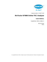
● Instrument Card (→ page 20, Figure 1)
● Dimensioned drawing
● Layout drawing
● Substance flow diagram
● Wiring diagram
● Parts list for components

Important Information
20 TOCOR700 Operating Instructions V4.1 8011462 © SICK AG
Figure 1 Instrument card (example)
5043- 11090045221210
1
#
#
20 +- 10% l/h
67 ml / 100 g
Na2S2O8
10
l
ml
0
comments
basic meas. Range
(ppm CO2)
part No. / serial No.
100
100
08123456
Company
1029673
800
material of pump
hose
place for nameplate
sample to drain
640416
purchase order No.
PO 123456
order No
ZTA 1234567
VUdrac tnemurtsni TOCOR 700
Code
customer No.
123456
drawing No.
.oN lairesremotsuc
10. Sep 08
date of delivery
10. Sep 08
part No.:
1203079
QT 70011
rain water
T
OC
(i
nc
l
u
d
es
TIC
st
ri
ppe
r
)
salt conc. < 2 g/l
1,42
max. salt conc.
component to be
measured
place of installation
consumption
application
Kumm
TAG No:
power supply
checkout
10. Sep 08
Utermark
0
release
dosing pump M10
classication
cabinet / dimensions
reactor
basic meas. range mg/l
2nd output range
output signals
no. of sampling points
meas. range 50 mg/lC
12 rpm - 6027110
pump hose 2 V02
0
ml/h
ISM-3 bk-bk id=0,76mm
none
1 point
carrier gas
ml/h
pump hose 4 V04
20
ml/h
none
ISM-3 or-wh id=0,64mm
0
pump hose 1 V01
without 2nd output range
4-20 mA
No Ex zone
PS 1200x500x290 mm
UV-reactor
internal UV-version
30
ml/h
ambient temp.
sample to reactor
230V / 50Hz
400 VA
indoors
+5 - 35 °C
g
sample to stripperISM-3 wh-wh id=1,02mm
reagent consumption
50
ml/h
H2SO4 (98%)
demin. water
pump hose 3 V03
pump hose 5 V05
ml/h
30,2 % H2SO4 (pH1)+ 20 g/l Na2S2O8
17
dosing pump M11
pump hose set SR25
reagent for operation
reagent to reactor
reagent to stripper
l /
week
receipe
X - NN
conguration TOC:CO2
/
5
19
CO2-analyser
S715 UNOR
gas ow
Tygon LFL (PVC-transparent)
manual
SR25 10 rpm - 6032012
SR25 DI=4,8x1,6 opaque
manual
1 / 18002.60.81 slx.5-1-8V-ROCOTetraketäreG
SICK|MAIHAK
Maihak AG
22399 Hamburg
/