Page is loading ...

Your new tool has been engineered and manufactured to WEN’s highest standards for dependability,
ease of operation, and operator safety. When properly cared for, this product will supply you years
of rugged, trouble-free performance. Pay close attention to the rules for safe operation, warnings,
and cautions. If you use your tool properly and for intended purpose, you will enjoy years of safe,
reliable service.
IMPORTANT:
NEED HELP? CONTACT US!
Have product questions? Need technical support?
Please feel free to contact us at:
800-232-1195
WENPRODUCTS.COM
(M-F 8AM-5PM CST)
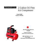
Model # 2281
bit.ly/wenvideo
For replacement parts visit
WENPRODUCTS.COM
1-GALLON
AIR COMPRESSOR
224876

TECHNICAL DATA
Model Number:
Motor:
Capacity:
Max PSI:
Approximate Cut-in Pressure:
Approximate Cut-out Pressure:
Air Outlet:
Air Flow:
Compression Process:
Product Dimensions:
Weight:
2281
120V, 3.5A, 60 Hz
1 Gallon
125 PSI
95 PSIG
125 PSIG
Quick-Coupler, 1/4˝ NPT
0.6 CFM at 90 PSI
0.8 CFM at 40 PSI
Single Stage
13.3 x 11.5 x 11.2 inches
24.25 pounds
2
TABLE OF CONTENTS
Technical Data
2
3
4
6
7
8
10
11
12
14
General Safety Rules
Specific Rules for Air Compressors
Know Your Compressor
Operation
Warranty
Parts List & Exploded View
Maintenance
Electrical Information
Troubleshooting

3
WARNING: Dust generated from certain materials can be hazardous to your health. Always operate
the tool in a well-ventilated area and wear dust mask. Use dust collection systems when processing
wood and plastics. Dust extractors or dust bags must not be connected when processing metals.
PERSONAL SAFETY
1. Stay alert. Watch what you are doing and use common sense when operating a power tool. Do not use a power
tool while you are tired or under the influence of drugs, alcohol or medication. A moment of inattention while op-
erating power tools may result in serious personal injury.
2. Do not wear loose clothing, gloves, neckties, or jewelry (rings, watches, etc.) when operating the tool. Inappropri-
ate clothing and items can get caught in moving parts and draw you in. Always wear non-slip footwear and tie back
long hair.
3. Use personal protective equipment. Always wear safety goggles at all times that comply with ANSI Z87.1. Use ear
protection such as plugs or muffs during extended periods of operation. Wear work gloves to protect your hands.
Wear a face mask or dust mask to fight the dust.
4. Keep proper footing and balance at all times and do not overreach when operating the power tool.
Safety is a combination of common sense, staying alert and knowing how your item works.
SAVE THESE SAFETY INSTRUCTIONS.
WARNING! Read all safety warnings and all instructions. Failure to follow the warnings and instruc-
tions may result in electric shock, fire and serious injury. To avoid mistakes and serious injury, do not
plug in your tool until the following steps have been read and understood.
WORK AREA SAFETY
1. Keep work area clean and well lit. Cluttered or dark areas invite accidents. Do not work on floor surfaces that are
slippery with sawdust or wax. Keep the ground clear of tripping hazard.
2. Do not operate power tools in explosive atmospheres, such as in the presence of flammable liquids, gases or dust.
Power tools create sparks which may ignite the dust or fumes.
3. Keep bystanders at a safe distance from the work area. Never allow children or pets near the tool.
ELECTRICAL SAFETY
1. Do not expose power tools to rain or wet conditions. Water entering a power tool will increase the risk of electric
shock.
2. Power tool plugs must match the outlet. Never modify the plug in any way. Modified plugs with non-matching
outlets will increase the risk of electric shock.
3. Check all power supplies periodically. Do not use defective cords. Damaged or entangled cords increase the risk
of electric shock.
4. Do not abuse the cord. Never use the cord for carrying, pulling or unplugging the power tool. Keep cord away
from heat, oil, sharp edges or moving parts.
GENERAL SAFETY RULES

4
GENERAL SAFETY RULES
WARNING: To avoid mistakes and serious injury, do not plug in your tool until the following steps have
been read and understood.
1. Use your air compressor in accordance with these instructions, taking into account working conditions and the
task at hand. Use of the compressor for operations other than its intended use could result in personal injury.
2. Always operate the compressor in a well ventilated area away from combustible materials, gasoline, or solvent
vapors. Your air compressor must be kept at least 20 feet away from explosive vapors.
3. Do not use your air compressor if the pressure switch does not turn on and off. An air compressor that cannot
be controlled with the switch is dangerous and must be repaired.
4. Check for misalignment or binding of moving parts, breakage of parts and any other condition that may affect
your air compressor’s operation. If damaged, have your air compressor repaired by a qualified service technician
before using it again. Many accidents are caused by poorly maintained compressors.
SPECIFIC RULES FOR AIR COMPRESSORS
POWER TOOL USE AND CARE
1. Avoid accidental start-ups. Make sure the power switch is in the OFF position before connecting the plug to a
power source or carrying the tool.
2. Check power tool for damaged parts. Check for misalignment of moving parts, jamming, breakage, improper
mounting, or any other conditions that may affect the tool’s operation. Do not use the power tool if the switch does
not turn ON/OFF. Any part that is damaged should be properly repaired or replaced before use.
3. Do not force the tool to do a job for which it was not designed. Use the correct power tool and accessories and
follow the instructions for your application to prevent hazardous situations.
4. Remove adjustment tools. Always make sure all adjustment tools or wrenches are removed from the tool before
turning on the power tool.
5. Keep guards in place and in working order before operating the tool. All protection and safety devices must be
in place after completing repair and maintenance procedures
6. Never leave a running tool unattended. Do not leave the tool until it has come to a complete stop.
POWER TOOL MAINTENANCE
1. Always disconnect the power cord plug from the electrical outlet when making adjustments, changing parts, or
storing power tools. Such preventive safety measures reduce the risk of starting the power tool accidentally.
2. Maintain power tools properly. Safely store power tools out of the reach of children. Always keep tools clean and
in good working order. Follow instructions for lubricating and changing accessories.
3. Only have your power tool serviced by a qualified repair person using only identical replacement parts. Use of
any other part can cause personal injury and damage to the tool.

5
SPECIFIC RULES FOR AIR COMPRESSORS
5. Keep your air compressor in a well-ventilated area. Do not cover during use.
6. Do not spray flammable liquids in a confined area or towards a hot surface. The spray area must be well-ventilat-
ed. Do not smoke while spraying. Do not spray when a spark or flame is present.
7. Do not adjust the regulator higher than the marked maximum pressure of any attached pneumatic tools or equip-
ment.
8. Do not direct the air stream at people or animals.
9. Do not use your air compressor to supply breathing air.
10. To prevent burns or other injuries, do not touch any exposed metal parts on compressor during or immediately
after operation. The air compressor’s cylinder head and air lines get hot during operation and will remain hot for
several minutes after operation.
11. Do not leave your air compressor unattended for an extended period while plugged in. Unplug compressor and
detach hoses and accessories after use.
12. Drain tank daily or after use. Internal rust causes tank failures and explosions.
13. Do not use the air hose to move your air compressor.
14. Do not grind, puncture, torch or in any way modify the compressor’s tank.
15. Disconnect the plug from the power source and drain all air from the tank before making any adjustments,
changing accessories, or storing your air compressor. This reduces the risk of starting your air compressor acciden-
tally.
16. Maintain your air compressor. Keep your air compressor clean for maximum performance. Follow the instruc-
tion for maintenance and changing accessories if necessary. Keep your air compressor dry, clean and free from oil
and grease.
17. Store your air compressor out of the reach of children and do not allow people unfamiliar with either the com-
pressor or these instructions to operate it. An air compressor is dangerous in the hands of an untrained user.
18. Ignoring any of the above rules and guidelines automatically voids the warranty for the unit.

ELECTRICAL INFORMATION
GROUNDING INSTRUCTIONS
IN THE EVENT OF A MALFUNCTION OR BREAKDOWN, grounding provides the path of least resistance
for an electric current and reduces the risk of electric shock. This tool is equipped with an electric cord that has an
equipment grounding conductor and a grounding plug. The plug MUST be plugged into a matching outlet that is
properly installed and grounded in accordance with ALL local codes and ordinances.
DO NOT MODIFY THE PLUG PROVIDED. If it will not fit the outlet, have the proper outlet installed by a
licensed electrician.
IMPROPER CONNECTION of the equipment grounding conductor can result in electric shock. The conduc-
tor with the green insulation (with or without yellow stripes) is the equipment grounding conductor. If repair or
replacement of the electric cord or plug is necessary, DO NOT connect the equipment grounding conductor to a
live terminal.
WARNING: This tool is for indoor use only. Do not expose to rain or use in damp locations.
GUIDELINES AND RECOMMENDATIONS FOR EXTENSION CORDS
Make sure your extension cord is in good condition. When using an extension cord, be sure to use one heavy
enough to carry the current your product will draw. An undersized cord will cause a drop in line voltage resulting
in loss of power and overheating. The table below shows the correct size to be used according to cord length and
nameplate ampere rating. When in doubt, use a heavier cord. The smaller the gauge number, the heavier the cord.
Make sure your extension cord is properly wired and in good condition. Always replace a damaged extension cord
or have it repaired by a qualified person before using it. Protect your extension cords from sharp objects, excessive
heat and damp/wet areas.
Use a separate electrical circuit for your tools. This circuit must not be less than a #12 wire and should be protected
with a 15 A time-delayed fuse. Before connecting the motor to the power line, make sure the switch is in the OFF
position and the electric current is rated the same as the current stamped on the motor nameplate. Running at a
lower voltage will damage the motor.
WARNING: This tool must be grounded while in use to protect the operator from electric shock.
AMPERAGE
REQUIRED GAUGE FOR EXTENSION CORDS
25 ft. 50 ft. 100 ft. 150 ft.
3.5 A 18 gauge 16 gauge 16 gauge 14 gauge
CHECK with a licensed electrician or service personnel if you do not com-
pletely understand the grounding instructions or whether the tool is properly
grounded.
USE ONLY THREE-WIRE EXTENSION CORDS that have three-pronged
plugs and outlets that accept the tool’s plug as shown in Figure A. Repair or
replace a damaged or worn cord immediately.
CAUTION: In all cases, make certain the outlet in question is properly ground-
ed. If you are not sure, have a licensed electrician check the outlet.
6
Figure A

KNOW YOUR AIR COMPRESSOR
Tank
Tank Drain Valve
Motor
Air Line Outlet
Rubber Foot
Pressure Switch
Pressure Relief Valve
(Behind Switch Box)
Tool Pressure Gauge
Tool Pressure
Regulator
Tank Pressure Gauge
Handle
Carefully unpack the air compressor from the box. Check all components and compare against the graph below.
If any part is damaged or missing, please contact our customer service at (800) 232-1195, M-F 8-5 CST.
7

5. Turn the pressure switch (Fig. 3 - 2) to the ON/AUTO position (to the left) to allow the compressor to auto-
matically start up and shut down depending on its need for air. NOTE: Make sure this switch is set to OFF before
unplugging, plugging in, or storing the compressor.
WARNING: To prevent burns or other injuries, DO NOT touch the compressor while it is running. Al-
low it to cool before handling or servicing. Keep children away from the compressor at all times.
6. Allow the compressor to reach the desired PSI on the tank pressure gauge before turning off the compressor.
If left on, the compressor will reach its maximum PSI of 125 and turn off automatically. Then once the tank PSI
lowers to 95 PSI, the compressor will automatically turn back on until it reaches its max PSI again. Check the tank
pressure gauge (Fig. 3 - 3). DO NOT ALLOW THE COMPRESSOR TO FILL UP TO MORE THAN 125 PSI.
7. Turn the tool pressure regulator (Fig. 3 - 4) to control the output of air flow from the compressor. The tool pres-
sure gauge (Fig. 3 - 5) will show you the current pressure from the air line outlet. Make sure that this pressure is not
higher than the working pressure of any pneumatic tools hooked up to the compressor. Using a pressure higher
than the rated pressure of an attached tool creates the possibility of damaging or, in worse case scenarios, bursting
said power tool. Using a pressure that is too low for a tool can result in misfires and improper function.
OPERATION
STARTING THE COMPRESSOR
1. Before each use, inspect the general condition of the machine. Any dam-
aged parts should be replaced using identical replacement parts by a quali-
fied service technician before operation.
2. Check that the pressure switch is switched to the OFF position (to the
right) and the tank drain valve is closed (perpendicular to the drain tube).
3. Connect an air hose (not included) to the air line outlet (Fig. 3 - 1). Make
sure the air hose is rated high enough to handle the max PSI of the com-
pressor (125 PSI).
NOTE: All connections should be made with thread seal tape (not includ-
ed) properly wrapped around the threads of the accessory connections.
4. Connect the electrical plug to a power supply. NOTE: The compressor
must be at least one foot from any wall or obstruction in a well-ventilated
area to maximize proper air flow. Do not cover the compressor.
1
2
3
4
5
Fig. 1
Fig. 2
Fig. 3
AUTO
OFF
OPEN
CLOSED
TURNING THE COMPRESSOR ON & OFF (Fig. 1)
1. Move the switch to the left to set the tool to ON/AUTO mode.
2. Move the switch to the right to set the tool OFF mode.
CLOSING & OPENING THE TANK DRAIN VALVE (Fig. 2)
1. Before operation, close the tank drain valve by moving the valve clock-
wise (perpendicular to the drain tube).
2. After operation, drain the tank by moving the tank drain valve counter-
clockwise (in line with the drain tube) to open.
8

WARNING: Wear safety goggles when opening drain valve as escaping air and moisture may propel de-
bris that may cause eye injury. Wear ear protection as it can be very loud when the relief valve ring is open.
THERMAL OVERLOAD PROTECTOR
The thermal overload protector shuts down the motor when it is overloaded. When the thermal overload trips,
the air compressor will stop working. Let the motor cool down for a few minutes. To restart the motor, unplug the
power cord and plug it back in. Put the pressure switch to ON/AUTO position.
OPERATION
Fig. 4
SHUTTING DOWN THE COMPRESSOR
1. Turn the pressure switch to the OFF position. Then unplug the power
cord.
2. Reduce pressure in the tank through the outlet hose or by pulling the
pressure relief valve ring (Fig. 4 - 1). This is an emergency overpressure
relief. When pulled open, it will lower the pressure down to 75 PSI and
close automatically. To lower the pressure below 75 PSI or to drain the
tank, pull on the ring and hold it open.
3. Drain water from the tank by opening the tank drain valve (counter-
clockwise) on the bottom of the tank (Fig. 2).
1
9

MAINTENANCE
WARNING: Always shut off and unplug the compressor and relieve all air pressure from the system before
performing any cleaning or inspection on the air compressor.
CLEAN AND INSPECT DAILY
1. Pull the pressure release valve ring to open the valve after each operation (Fig. 4).
2. Open the tank drain valve (Fig. 2) underside the compressor to drain the tank daily after each operation. To mini-
mize moisture inside of the unit, tilt the compressor during drainage so that the drain valve is aimed directly towards
the ground. This will allow all moisture to drain completely and prevent the tank from corroding.
NOTE: Make sure to drain in before making adjustments or doing maintenance on the compressor.
3. Wipe the tool clean. Blow the tool clean using high compressed air, then use non-flammable cleaning solutions to
wipe exterior of the tool as necessary, particularly before storage. Do not soak tool with cleaning solutions. Such so-
lutions can damage internal parts. Keep the handle clean, dry and free from slippery substances such as oil or grease.
4. Inspect the machine components before operation to make sure that there are no damaged or worn parts. Re-
place any damaged parts immediately. Do not operate if there are any damaged components. Only repair using
identical replacement parts.
5. Do not overtighten connections to avoid creating leaks.
TESTING FOR LEAKS
Make sure all connections are tight and secure before testing for leaks. A small leak in any hoses or connectors will
greatly reduce the abilities of the compressor. To locate a leak, simply spray a mixture of soap and water across the
entire surface of both the tank and the hose (wherever the leak is believed to be). Bubbles will begin to appear if a
leak is indeed present. Fix immediately. Try to avoid getting soapy water near any of the inlets on the tank or the
pump.
STORAGE
Before storing the compressor, drain the tank by opening tank drain valve on the underside of the compressor (Fig.
2). This will drain the compressor to prevent moisture from collecting and rusting the inside of the tank. Pull on and
hold open the pressure release valve ring (Fig. 4) located next to the tank pressure gauge to relieve the remaining
pressure inside the tank. Do not store the air compressor in cold climates, as cold climates may create problems
with the motor while possibly freezing water condensation.
10

TROUBLESHOOTING
Problem Common Causes Solution
Air leaks from the regulator. Regu-
lator does not regulate pressure any
more.
The regulator has become damaged
or dirty.
Replace the regulator/internal parts.
Low PSI pressure and/or compres-
sor does not stop.
1. Tank drain valve is open.
2. Leaks in the unit.
3. Using too much air.
4. Air intake is obstructed.
5. Compressor is too small.
6. Blown gaskets/seals or leaking
valves/piston rings.
1. Close the drain valve (see Fig. 2
on page 8).
2. Check the unit for leaks (see
“Testing for Leaks” on page 10).
3. Use less air.
4. Make sure the unit is away from
the wall and that the air inlets are
not obstructed.
5. Check the requirements of the
pneumatic tool. Make sure the
specifications of this compressor
meet the requirements.
6. Replace necessary parts.
A large drop in the regulated pres-
sure gauge occurs once a pneumatic
tool or other air accessory is being
used.
The compressor is too small. Check the requirements of the
pneumatic tool. Make sure the
specifications of this compressor
meet the requirements.
Motor won’t run. 1. Tank pressure is too high.
2. Thermal overload protection on
the motor has been tripped.
3. Power source isn’t working.
4. The check valve (part 61 on page
12) is stuck open.
1. Motor will start automatically
once the tank pressure drops.
2. Let the motor cool down for a
few minutes. Unplug the unit and
plug it back in.
3. Examine the power source. Make
sure that your extension cord is of
the proper gauge.
4. Clean or replace the check valve.
Pressure relief valve opens. 1. Tank pressure is too high
2. Pressure switch is stuck.
1. Let the tank pressure drop.
2. Replace the pressure switch.
If problems still exist after consulting this list, or if you have any questions about the solutions provided above, feel
free to contact the WEN help line at 800-232-1195 (M to F, 8 to 5 CST) or email [email protected].
CAUTION: Stop using the tool immediately if any of the following problems occur or risk serious
personal injury. Have the repair or replacement performed by a qualified service technician before
operating this tool.
11

12
EXPLODED VIEW AND PARTS LIST

13
EXPLODED VIEW AND PARTS LIST
No. Part No. Description Qty.
1 2281-001
Cross Recess Pan Head
Screw M4X8
4
2 2281-002 Washer 4 11
3 2281-003 Shroud 1
4 2281-004 Circlip For Shaft 12 1
5 2281-005 Connecting Rod 1
6 2281-006 Deep Groove Ball Bearing 6201 2
7 2281-007 Crankshaft 1
8 2281-008
Cross Recess Pan Head Screw
M4X10
7
9 2281-009 Spring Washer 4 7
10 2281-010 Crankcase 1
11 2281-011 Stator Assembly 1
12 2281-012 Sleeve 1
13 2281-013 Rotator Assembly 1
14 2281-014 Deep Groove Ball Bearing 6200 1
15 2281-015 Wave Washer 30 1
16 2281-016 Bearing Cover 1
17 2281-017 Hex Head Cap Screw M6*30-8.8 4
18 2281-018 Washer Φ6 4
19 2281-019 Cushion Blocking 4
20 2281-020 Bushing I 4
21 2281-021 Washer 6 4
22 2281-022 Spring Washer 6 4
23 2281-023 Hex Nut M6 4
24 2281-024 Washer 5 8
25 2281-025 Spring Washer 8
26 2281-026 Hex Bolt 8.8 4
27 2281-027 Fan Assembly 1
28 2281-028 Circlip For Shaft 9 1
29 2281-029 Air Duct 1
30 2281-030 Washer Φ4 1
31 2281-031 Spring Washer Φ4 1
32 2281-032
Cross Recessed Pan Head Screw
M4X8
1
33 2281-033 O Ring Φ37*Φ2.5N41 2
34 2281-034 Capacitor 30Uf 1
35 2281-035 Thermal Protector-Ma 1
36 2281-036 Power Cord 1
37 2281-037 Strength Relief 3
38 2281-038 Capacitor Case 1
39 2281-039 Air Filter 1
40 2281-040 Air Filter Housing 1
No. Part No. Description Qty.
41
2281-041
Cord Cussion 1
42
2281-042
Cylinder Adjusting Pad 1
43
2281-043
Cylinder 1
44
2281-044
Cylinder Seal 1
45
2281-045
Cross Recessed Pan Head M3*6 2
46
2281-046
Washer Φ3 1
47
2281-047
Inlet Valve 1
48
2281-048
Valve Plate 1
49
2281-049
Outlet Valve 1
50
2281-050
Valve Stopper 1
51
2281-051
Elbow 1
52 2281-052
Hexagon Socket Head Cap
Screws
4
53
2281-053
Cylinder Cap 1
54
2281-054
Cylinder Cap Seal 1
55
2281-055
Piston Compression Ring 1
56
2281-056
Piston Ring 1
57
2281-057
Hex Socket Head Screw 1
58
2281-058
Tank Assembly 1
59
2281-059
Taper Sleeve 4
60
2281-060
Ferrule Nut 1
61
2281-061
Check Valve 1
62
2281-062
T Joint 1
63
2281-063
Nut 3
64
2281-064
Inlet Tube Φ6*1mm 1
65
2281-065
Exhaust Tube Φ6*1mm 1
66
2281-066
Coupler 1
67
2281-067
Regulator 1
68
2281-068
Pressure Gauge Axial Direction 1
69
2281-069
1/4” Straight Joint 1
70
2281-070
Pressure Switch 1
71
2281-071
Pressure Gauge Axial Direction 1
72
2281-072
Power Cord With Plug 1
73
2281-073
Safety Valve 1
74
2281-074
Rubber Grip 1
75
2281-075
Roll Bar Cap 2
76
2281-076
Drain Valve 1
77
2281-077
Rubber Feet 4
78
2281-078
Washer Φ4 4
79
2281-079
Socket Head Cap Screw 4
80
2281-080
Thermal Protector 1

14
WEN Products is committed to building tools that are dependable for years. Our warranties are consistent with
this commitment and our dedication to quality.
LIMITED WARRANTY OF WEN CONSUMER POWER TOOLS PRODUCTS FOR HOME USE
GREAT LAKES TECHNOLOGIES, LLC (“Seller”) warrants to the original purchaser only, that all WEN con-
sumer power tools will be free from defects in material or workmanship for a period of two (2) years from date of
purchase. Ninety days for all WEN products, if the tool is used for professional use.
SELLER’S SOLE OBLIGATION AND YOUR EXCLUSIVE REMEDY under this Limited Warranty and, to
the extent permitted by law, any warranty or condition implied by law, shall be the repair or replacement of parts,
without charge, which are defective in material or workmanship and which have not been misused, carelessly
handled, or misrepaired by persons other than Seller or Authorized Service Center. To make a claim under this
Limited Warranty, you must make sure to keep a copy of your proof of purchase that clearly defines the Date of
Purchase (month and year) and the Place of Purchase. Place of purchase must be a direct vendor of Great Lakes
Technologies, LLC. Third party vendors such as garage sales, pawn shops, resale shops, or any other secondhand
merchant void the warranty included with this product. Contact [email protected] or 1-800-232-
1195 to make arrangements for repairs and transportation.
When returning a product for warranty service, the shipping charges must be prepaid by the purchaser. The prod-
uct must be shipped in its original container (or an equivalent), properly packed to withstand the hazards of ship-
ment. The product must be fully insured with a copy of the warranty card and/or the proof of purchase enclosed.
There must also be a description of the problem in order to help our repairs department diagnose and fix the
issue. Repairs will be made and the product will be returned and shipped back to the purchaser at no charge.
THIS LIMITED WARRANTY DOES NOT APPLY TO ACCESSORY ITEMS THAT WEAR OUT FROM
REGULAR USAGE OVER TIME INCLUDING BELTS, BRUSHES, BLADES, ETC.
ANY IMPLIED WARRANTIES SHALL BE LIMITED IN DURATION TO TWO (2) YEARS FROM
DATE OF PURCHASE. SOME STATES IN THE U.S., SOME CANADIAN PROVINCES DO NOT AL-
LOW LIMITATIONS ON HOW LONG AN IMPLIED WARRANTY LASTS, SO THE ABOVE LIMITA-
TION MAY NOT APPLY TO YOU.
IN NO EVENT SHALL SELLER BE LIABLE FOR ANY INCIDENTAL OR CONSEQUENTIAL DAM-
AGES (INCLUDING BUT NOT LIMITED TO LIABILITY FOR LOSS OF PROFITS) ARISING FROM
THE SALE OR USE OF THIS PRODUCT. SOME STATES IN THE U.S. AND SOME CANADIAN
PROVINCES DO NOT ALLOW THE EXCLUSION OR LIMITATION OF INCIDENTAL OR CON-
SEQUENTIAL DAMAGES, SO THE ABOVE LIMITATION OR EXCLUSION MAY NOT APPLY TO
YOU.
THIS LIMITED WARRANTY GIVES YOU SPECIFIC LEGAL RIGHTS, AND YOU MAY ALSO HAVE
OTHER RIGHTS WHICH VARY FROM STATE TO STATE IN THE U.S., PROVINCE TO PROVINCE
IN CANADA AND FROM COUNTRY TO COUNTRY.
THIS LIMITED WARRANTY APPLIES ONLY TO PORTABLE ELECTRIC TOOLS, BENCH POW-
ER TOOLS, OUTDOOR POWER EQUIPMENT AND PNEUMATIC TOOLS SOLD WITHIN THE
UNITED STATES OF AMERICA, CANADA AND THE COMMONWEALTH OF PUERTO RICO. FOR
WARRANTY COVERAGE WITHIN OTHER COUNTRIES, CONTACT THE WEN CUSTOMER SUP-
PORT LINE.
LIMITED TWO YEAR WARRANTY


THANKS FOR
REMEMBERING
/