
RM-2 1.1 REV. A EN.doc www.roger.pl 06-01-05
R
ELAY
M
ODULE
RM-2
V
1.1
D
ESCRIPTION
The RM-2 is usually used to increase a power switched by an output line and/or for
electrical separation between output (e.g. signal output of an access controller) and
load (e.g. door lock, siren etc.).
The RM-2 relay module provides two power relays along with transistor type
triggering circuits. Each relay can be triggered either by low or high voltage level
applied to adequate input. Using jumpers, installer can select the triggering
methods independently for each relay. The triggering inputs of RM-2 are
characterized by relatively high input resistance (app. 15kΩ) so the majority of the
transistor type outputs (even a very week 5mA open collector line) can successfully
trigger the relay’s coil. Each relay offers single, dry type, contact (COM/NO/NC -
Form C) 1.5A rated. If needed the common contact (COM) of a relay can be
internally (biased) connected to supply minus or plus alternatively it can be left
unconnected (dry). Either NO-COM or NC-COM pairs of contacts are protected
from spikes through over voltage elements (Metal Oxide Varistors – MOV). The use
of MOVs significantly extends the live time of contacts and improve overall
switching performance provided by the relays. The activation of each relay is
indicated on relevant LED (red color) located on printed board.
I
NSTALLATION
Locate module in adequate compartment or installation box, far from sources of
heat and moisture. All electrical connections and jumper settings must be carried
out prior to power up. Once wiring is complete, power up the device and perform
testing. When module is installed in adequate housing which deliver sufficient
protection against outdoor conditions it may be located in external locations (RM-2
offers -25/+60 °C operation).
Note: The maximum voltage switched by relay contacts must not exceed 28V
AC/DC.
T
ECHNICAL
S
PECIFICATION
Supply input: 10.0 ...16VDC
Current consumption : ~40mA per each triggered relay @12VDC
Load :
1.5A/28V
AC
/
DC
Input resistance:
15
K
Ω
Triggering level HIGH :
>
5V
Triggering level LOW: < 4V
Temperature: -25/+60 °C
Relative Humidity: 10-95% (without condensation)
Dimensions : 81 x 60
Weight :
46
G
.
O
RDERING
C
ODES
RM - 2 Electronic module (board)
M2 - Box Plastic case for RM-2 module

89
29
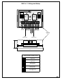
RM-2 v1.1 Wiring and Setup
COM NO2IN2IN112V NC1 TAMPER COMNO1 NC2
REL 2REL 1
Tamper
loop
LOW
HIGH
+12V
NC
GND
OUTPUT1
Settings
LOW
HIGH
+12V
NC
GND
OUTPUT2
Settings
Relay Module RM-2 v1.1
REL1 contacts REL2 contacts
DC input
(12V DC)
REL1
triggering input
REL2
triggering input
LOW
LOW
HIGH
HIGH
+12V
+12V
+12V
NC
NC
NC
GND
GND
GND
LOW level voltage (supply minus)
triggers relay
HIGH level voltage (supply minus)
triggers relay
Jumper settings
(refer to both REL1 and REL2 outputs)
COM contact
shorted internally
with supply plus
COM contact
shorted internally
with supply minus
Isolated COM contact
(dry)
Plastic case
(optional)
cdr191
-
 1
1
-
 2
2


Ask a question and I''ll find the answer in the document
Finding information in a document is now easier with AI
Related papers
-
Roger HRC102DR/HRC402DR Installation guide
-
-
-
-
-
-
-
-
-

