Page is loading ...

Dell EMC PowerSwitch S4810–ON Installation
Guide
August 2020
August 2020
Rev. A02

Notes, Cautions, and Warnings
NOTE: A NOTE indicates important information that helps you make better use of your computer.
CAUTION: A CAUTION indicates either potential damage to hardware or loss of data and tells you how to avoid the
problem.
NOTE: A WARNING indicates a potential for property damage, personal injury, or death.
© 2014 - 2020 Dell Inc. or its subsidiaries. All rights reserved. Dell, EMC, and other trademarks are trademarks of Dell Inc. or its subsidiaries. Other
trademarks may be trademarks of their respective owners.

Chapter 1: About this Guide............................................................................................................. 5
Information symbols.............................................................................................................................................................. 5
Related Documents...............................................................................................................................................................5
Chapter 2: The S4810–ON System................................................................................................... 6
Introduction............................................................................................................................................................................ 6
Orderable S4810–ON Components...............................................................................................................................7
Prerequisite.............................................................................................................................................................................7
Features.................................................................................................................................................................................. 8
Ports........................................................................................................................................................................................8
System Status........................................................................................................................................................................8
LED Displays..................................................................................................................................................................... 8
Chapter 3: Site preparations........................................................................................................... 11
Site Selection.........................................................................................................................................................................11
Cabinet Placement................................................................................................................................................................11
Rack Mounting...................................................................................................................................................................... 11
Grounding (Optional)...........................................................................................................................................................12
Fans and Airflow...................................................................................................................................................................12
Power.....................................................................................................................................................................................12
Storing Components............................................................................................................................................................12
Chapter 4: Install the S4810–ON..................................................................................................... 13
Installing the S4810–ON Chassis in a Rack or Cabinet................................................................................................... 13
Two-post mounting brackets....................................................................................................................................... 13
Two-post installation......................................................................................................................................................14
Attach the mounting brackets......................................................................................................................................15
Four-post installation..................................................................................................................................................... 16
Ground cable.........................................................................................................................................................................17
Installing the SFP+ and QSFP+ Optics............................................................................................................................. 18
Remove the SFP+ and QSFP+ Optics........................................................................................................................ 18
Splitting QSFP+ Ports to SFP+ Ports...............................................................................................................................18
System power-on.................................................................................................................................................................19
AC Power........................................................................................................................................................................ 19
After installation................................................................................................................................................................... 19
Chapter 5: Power supplies............................................................................................................. 20
Components.........................................................................................................................................................................20
AC power supply installation...............................................................................................................................................21
AC power supply replacement............................................................................................................................................21
Chapter 6: Fans............................................................................................................................ 23
Components.........................................................................................................................................................................23
Fan module installation........................................................................................................................................................24
Contents
Contents 3

Fan module replacement.................................................................................................................................................... 24
Chapter 7: Console Ports...............................................................................................................25
Accessing the RJ-45 console port (RS-232).................................................................................................................. 25
RJ-45 console port..............................................................................................................................................................26
Before you install an operating system.............................................................................................................................26
ONIE Service Discovery................................................................................................................................................26
Chapter 8: Specifications.............................................................................................................. 28
Chassis Physical Design......................................................................................................................................................28
IEEE Standards.............................................................................................................................................................. 29
Agency Compliance.............................................................................................................................................................29
USA Federal Communications Commission (FCC) Statement............................................................................... 29
European Union EMC Directive Conformance Statement.......................................................................................29
Japan: VCCI Compliance for Class A Equipment...................................................................................................... 30
Korean Certification of Compliance............................................................................................................................ 30
Safety Standards and Compliance Agency Certifications........................................................................................30
Electromagnetic Compatibility (EMC).........................................................................................................................31
Product Recycling and Disposal................................................................................................................................... 31
Removing the SD card.................................................................................................................................................. 32
Replacing the battery....................................................................................................................................................32
Chapter 9: Technical support......................................................................................................... 35
Support................................................................................................................................................................................. 35
4
Contents

About this Guide
This guide provides site preparation recommendations, step-by-step procedures for rack mounting and desk mounting, inserting optional
modules, and connecting to a power source.
.
CAUTION: To avoid electrostatic discharge (ESD) damage, wear grounding wrist straps when handling this equipment.
NOTE: Only trained and qualified personnel can install this equipment. Read this guide before you install and power up
this equipment. This equipment contains two power cords. Disconnect both power cords before servicing.
NOTE: This equipment contains optical transceivers, which comply with the limits of Class 1 laser radiation.
NOTE: When no cable is connected, visible and invisible laser radiation may be emitted from the aperture of the optical
transceiver ports. Avoid exposure to laser radiation and do not stare into open apertures.
Topics:
• Information symbols
• Related Documents
Information symbols
This book uses the following information symbols:
NOTE: The Note icon signals important operational information.
CAUTION: The Caution icon signals information about situations that could result in equipment damage or loss of data.
NOTE: The Warning icon signals information about hardware handling that could result in injury.
NOTE: The ESD Warning icon requires that you take electrostatic precautions when handling the device.
Related Documents
NOTE:
For more information about the S4810–ON system, see the
Dell Networking S4810–Open Networking (ON)
Getting Started Guide
. For the most recent documentation, go to http://www.dell.com/support/my-support.
1
About this Guide 5

The S4810–ON System
The following sections describe the Dell EMC S4810–ON system.
Topics:
• Introduction
• Prerequisite
• Features
• Ports
• System Status
Introduction
The Dell EMC S4810–ON platform is a next-generation switch/router designed to meet the requirements for distributed data center
cores.
It is a one-rack unit (U) chassis that supports 48 ports of 10 GbE small form-factor pluggable plus (SFP+) and four quad small form-factor
pluggable plus (QSFP+) ports. For system access, the S4810–ON includes an RS-232/RJ-45 console port and a management port for
system access.
The S4810–ON I/O (I/O) side contains the 48 ports of 10 GbE and four uplink ports of 40 GbE QSFP+ autosensing ports and
management ports.
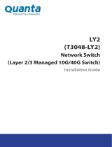
Figure 1. S4810–ON I/O-Side View
1. System LEDs
2. RS-232/RJ-45 Console Port
3. Management (Ethernet) Port
4. 40GE QSFP+ Ports
5. 10GE SFP+ Ports
The S4810–ON power supply unit (PSU) side (shown in the following figure) contains the PSU and fan modules.
2
6 The S4810–ON System

Figure 2. S4810–ON PSU-Side View
1. Mounting Bracket
2. Fan Module 1
3. Fan Module 2
4. Mounting Bracket
5. Power Supply (PSU2)
6. Power Supply (PSU1)
7. Grounding Screw
Orderable S4810–ON Components
You can order the S4810–ON system in several different configurations. You can also order optional modules and optics separately.
You can order the following supported hardware components.
• 48-port 10G SFP+ with four QSFP+, 40G ports, one AC power supply, and two fan subsystems (airflow from I/O side to power supply
side)
• 48-port 10G SFP+ with four QSFP+, 40G ports, one AC power supply, and two fan subsystems (airflow from power supply side to I/O
side)
• S4810–ON Series — Fan with airflow from the I/O side to the PSU side
• S4810–ON Series — Fan with airflow from the PSU side to the I/O side
• S4810–ON Series — AC Power supply with airflow from the I/O side to the PSU side
• S4810–ON Series — AC Power supply with airflow from the PSU side to the I/O side
For a list of supported optics, contact your Dell EMC sales representative.
Prerequisite
To successfully install the S4810–ON, ensure that you have the following components.
• S4810–ON chassis
• At least one grounded AC power source per chassis
• Cable to connect the AC power source to the chassis (US power cables included)
• Mounting brackets for rack installation (included)
• Screws for rack installation and #1 and #2 Phillips screwdrivers (not included)
• Ground cable (not included, optional)
• Ground cable screws (included)
• Copper/fiber cables
Other optional components are:
• Additional power supply unit
• Additional fan module
• Additional mounting brackets (if installing in a four-post rack or cabinet)
The S4810–ON System
7

Features
The S4810–ON offers the following features.
• S4810–ON CPU and switch processor
• Hot-swappable redundant power supply
• 19 inch rack-mountable
• Standard 1U chassis height
Ports
The S4810–ON offers the following ports.
• External Serial RS-232 port (RJ45 type)
• Remote management port
• 48–ports 10GbE and 4–ports 40GbE
• Universal serial bus (USB)-A port
• USB-B port
System Status
You can view S4810–ON status information using the light emitting diodes (LEDs).
LED Displays
The S4810–ON includes LED displays on the I/O side of the chassis (shown in the following figure).
When the S4810–ON powers up or reloads, the PSU LED is solid green. For additional LED information, see your third-party operating
software documentation.
The S4810–ON system LEDs are:
• System status (SYS)
• Stack Master indicator (MASTER)
• Fan status (FAN)
• Power status (PSU)
Also, the PSUs and fans have LEDs that indicate their individual status:
• PSU status
• Fan tray status
• System
8
The S4810–ON System

Figure 3. S4810–ON LEDs
1. SYS
2. MASTER
3. FAN
4. PSU
FAN LEDs
The top fan LED is FAN-1 LED; the bottom fan LED is FAN-0 LED.
LED Behavior on the S4810–ON System
The following S4810–ON system LED behavior is seen during U-Boot and ONIE operations.
Table 1. S4810–ON LED Behavior
LED Description
System Status LED
• Off — no power
• Blinking green — booting or system is in Diagnostic mode
• Solid green — normal operation
• Solid red — critical alarm
• Blinking red — non-critical alarm
Master LED
• Solid green — system is in Stacking Master mode
• Off — System is in Slave mode
Fan LED
• Solid green — Fan is powered on and running at the expected
RPM
The S4810–ON System 9

Table 1. S4810–ON LED Behavior (continued)
LED Description
• Solid yellow — Fan failed including incompatible airflow
direction
Power Status LED
• Off — no power
• Solid green — normal operations
• Blinking yellow — one power supply has failed
10 The S4810–ON System

Site preparations
The S4810–ON is suitable for installation as part of a common bond network (CBN).
You can install the system in:
• Network telecommunication facilities
• Data centers
• Other locations where the National Electric Code (NEC) applies.
For more information about S4810–ON specifications, see Specifications.
NOTE: Install the S4810–ON system into a rack or cabinet before installing any optional components.
Topics:
• Site Selection
• Cabinet Placement
• Rack Mounting
• Grounding (Optional)
• Fans and Airflow
• Power
• Storing Components
Site Selection
Install Dell EMC equipment in restricted access areas.
A restricted access area is one where service personnel can only gain access using a special tool, lock, key or other means of security.
Also, access is controlled by the authority responsible for the location.
Ensure that the area where you install your S4810–ON system meets the following safety requirements:
• Near an adequate power source. Connect the system to the appropriate branch circuit protection as defined by your local electrical
codes.
• The environmental temperature is between from 0° to 40°C (32° to 104°F).
• Relative humidity that does not exceed 85 percent noncondensing.
• In a dry, clean, well-ventilated, and temperature-controlled room, away from heat sources such as hot air vents or direct sunlight.
• The equipment is away from sources of severe electromagnetic noise.
• Position equipment in a rack or cabinet, or on a desktop with adequate space in the front, rear, and sides for proper ventilation and
access.
Cabinet Placement
Install the S4810–ON only in indoor cabinets that are designed for use in a controlled environment.
Do not install the S4810–ON in outside plant cabinets. For cabinet placement requirements, see Site Selection.
The cabinet must be a minimum cabinet size. Airflow must be according to the Electronic Industries Alliance (EIA) standard. Ensure that
there is a minimum of 12.7 cm (5 inches) between the intake and exhaust vents and the cabinet wall.
Rack Mounting
When you prepare your equipment rack, ensure that the rack is earth ground.
Ground the equipment rack to the same ground point the power service in your area uses. The ground path must be permanent.
3
Site preparations 11

Grounding (Optional)
Use the S4810–ON in a common bond network (CBN).
Connect the grounding cables as described in Install the S4810-ON.
Fans and Airflow
The S4810–ON fans support two airflow options.
Be sure to order the fans suitable to support your site’s ventilation. Use a single type of airflow fan in your system. Do not mix reverse and
normal airflows in a single S4810–ON chassis.
• Normal — airflow is from the I/O panel to the power supply. The grab-handle is labeled Exhaust.
• Reversed — airflow is from the power supply to the I/O panel. The grab-handle is labeled Intake.
For proper ventilation, position the S4810–ON in an equipment rack (or cabinet) with a minimum of 5 inches (12.7 cm) of clearance around
the exhaust vents. When you install two S4810–ON systems near each other, position the two chassis at least 5 inches (12.7 cm) apart to
permit proper airflow. The acceptable ambient temperature ranges are listed in Specifications.
The fan speed increases and decreases automatically based on the system’s state and temperature. The switch never intentionally turns
off the fans.
Power
To connect the chassis to the applicable power source, use the appropriate power cord with the S4810–ON. An AC power cord is included
with the system.
When installing AC systems, follow the requirements of the National Electrical Code, ANSI/NFPA 70 where applicable.
The system is powered-up as soon as the power cord is connected between the system and the power source.
CAUTION: Always disconnect the power cable before you service the power supply slots.
CAUTION: Use the power supply cord as the main disconnect device on the AC system. Ensure that the socket-outlet is
located/installed near the equipment and is easily accessible.
Storing Components
If you do not install your S4810-ON and components immediately, Dell Technologies recommends properly storing the system and all
optional components until you are ready to install them.
NOTE:
ESD damage can occur when components are mishandled. Always wear an ESD-preventive wrist or heel ground
strap when handling the S4810–ON and its accessories. After you remove the original packaging, place the S4810–ON
and its components on an anti-static surface.
Follow these storage guidelines:
• Storage temperature must remain constant ranging from -40°C to 70°C (-40° to 158°F).
• Store on a dry surface or floor, away from direct sunlight, heat, and air conditioning ducts.
• Store in a dust-free environment.
12
Site preparations

Install the S4810–ON
To install the S4810–ON system, Dell Technologies recommends completing the installation procedures in the order that is in this chapter.
Always handle the S4810–ON and its components with care. Avoid dropping the system or its field replaceable units (FRUs).
NOTE: ESD damage can occur if components are mishandled. Always wear an ESD-preventive wrist or heel ground strap
when handling the S4810–ON and its components. As with all electrical devices of this type, take all the necessary
safety precautions to prevent injury when installing this system.
Topics:
• Installing the S4810–ON Chassis in a Rack or Cabinet
• Ground cable
• Installing the SFP+ and QSFP+ Optics
• Splitting QSFP+ Ports to SFP+ Ports
• System power-on
• After installation
Installing the S4810–ON Chassis in a Rack or
Cabinet
The following sections describe how to install the S4810–ON in a rack or cabinet.
Two-post mounting brackets
The S4810–ON ships with mounting brackets (rack ears) and the required screws for a two-post rack or cabinet installation. The brackets
are sent in a package with the system.
NOTE:
Dell Technologies recommends attaching the brackets at the power supply unit (PSU) side. This set up provides
the greatest weight support for the chassis in the rack or cabinet.
To attach the brackets to the system, follow these steps.
1. Take the brackets and screws out of their packaging.
2. Attach the brackets to the PSU sides of the system using four screws for each bracket. Attach the bracket so that the “ear” is parallel
to the PSU and the outside of the system.
4
Install the S4810–ON 13

Figure 4. Attaching Mounting Brackets into a Two-Post Rack or Cabinet
1.
View from the chassis I/O side 2. Connect to the Rack or Cabinet (ears)
3. Screws 4. Screws
5. Connect to the Rack or Cabinet (ears) 6. Power Supply
Two-post installation
Ensure that there is adequate clearance surrounding the rack or within the cabinet to permit access and airflow.
To install a system into a two-post 19-inch equipment rack using the already attached mounting brackets, follow these steps.
NOTE:
Dell Technologies recommends using one person to hold the S4810–ON chassis in place while another person
attaches the brackets to the posts.
Attach the bracket “ears” to the rack or cabinet posts using the two screws for each bracket. Ensure that the screws are tightened firmly.
14
Install the S4810–ON

Figure 5. Installing the System into a Two-Post Rack or Cabinet
1. PSU1 2. PSU2
3. Rack Mounting Ears 4. Rack or Cabinet Post
Attach the mounting brackets
The S4810–ON ships with mounting brackets (rack ears) and the required screws for a two-post rack or cabinet installation.
To install the S4810–ON in a four-post rack or cabinet, you must order additional brackets separately. Use the brackets that are included
with the S4810–ON on the I/O side of system and use the brackets that you ordered separately on the PSU side of the system.
Unlike the two-post installation, the four-post installation requires attaching brackets to the rack before installing the system.
To attach the brackets to the rack or cabinet, follow these steps.
1. Ensure that there is adequate clearance surrounding the rack or within the cabinet to permit access and airflow.
2. Take the brackets and screws out of their packaging.
3. Attach the brackets to the PSU sides of the chassis using four screws for each bracket. Attach the bracket so that the “ear” is parallel
to the PSU and the outside of the chassis.
Install the S4810–ON
15

Figure 6. Attaching the Mounting Brackets into a Four-Post Rack or Cabinet
1.
View from the chassis I/O side 2. Connect to the rack or cabinet
3. Screws 4. Screws
5. Connect to the rack or cabinet (ears) 6. Power Supply
4. Attach the long bracket to each side of the chassis using the provided countersink screws. Use two screws on each side of the
chassis.
5. Install the rack mount ears into the I/O-facing posts using rack mount screws (not included with the system).
NOTE: Mount the rack mount ears so that the system is level when fully installed.
6. Using the provided pan head screws, attach the rack ears on the I/O facing posts to the long bracket (attached to the system). To
secure, tighten the pan head screws.
Four-post installation
To install a system into a four-post equipment rack using the already attached mounting brackets, follow these steps.
1. Ensure that there is adequate clearance surrounding the rack or within the cabinet to permit access and airflow.
2. Install the system into the rack. Ensure the long brackets dock into the previously installed rack ears.
3. Fasten the system to the PSU-facing posts using rack mount screws (not included with the system).
16
Install the S4810–ON

Figure 7. Installing the System into a Four-Post Rack or Cabinet
1.
I/O Side 2. Rack Ears
3. Long Brackets 4. Rack Ears
5. PSU Side
4. Use the provided pan head screws to attach the rack ears on the I/O-facing posts to the long bracket previously attached to the
system. Tighten the pan head screws to secure the system.
Ground cable
To attach the ground cable to the chassis, use a single M4x0.7 screw.
The cable itself is not included with the S4810–ON. To properly ground the chassis, Dell Technology recommends using a 6AWG one-hole
lug, #10 hole size, 63" spacing (not in shipping). The one-hole lug must be a UL recognized, crimp-type lug.
NOTE: The rack installation “ears” are not suitable for grounding.
CAUTION: Grounding conductors
must
be made of copper. Do not use aluminum conductors.
To connect the ground cable to the system, follow these steps.
NOTE:
Coat the one-hole lug with an antioxidant compound before crimping. Also, bring any unplated mating surfaces
to a shiny finish and coat with an antioxidant before mating. Plated mating surfaces must be clean and free from
contamination.
1. Take one M4x0.7 screw from the package.
2. Cut the cable to the needed length. The cable length must facilitate proper operation of the fault interrupt circuits. Dell Technologies
recommends using the shortest cable route allowable.
3. Attach the one-hole lug to the chassis using the supplied 10 to 32 screw with the captive internal tooth lock washer. Torque the screw
to 20 in-lbs.
Install the S4810–ON
17

Figure 8. Attaching the Ground Cable
a. Lug hole
b. Ground Screw
4. Attach the other end of the ground cable to a suitable ground point. The rack installation ears are not a suitable grounding point.
Installing the SFP+ and QSFP+ Optics
The S4810–ON has 48 SFP+ optical ports and four QSFP+ optical ports.
NOTE:
ESD damage can occur if components are mishandled. Always wear an ESD-preventive wrist or heel ground strap
when handling the S4810–ON and its components.
NOTE: When working with optical fibers, follow all warning labels and always wear eye protection. Never look directly
into the end of a terminated or unterminated fiber or connector as it may cause eye damage.
To install SFP+ or QSFP+ optics into an open port, follow these steps:
1. Position the optic so it is in the correct position. The optic has a key that prevents it from being inserted incorrectly.
2. Insert the optic into the port until it gently snaps into place.
NOTE: Both rows of QSFP+ ports require that the 40G optics be inserted with the tabs facing up.
Remove the SFP+ and QSFP+ Optics
Remove an optic by pushing the tab on the optic and sliding the optic from the port.
When removing optics with direct attach cables (DACs) from the port, pull the release tab firmly and steadily. Prior to pulling the release
tab, you may need to gently push the optic into the port to ensure it is seated properly. Do not jerk or tug repeatedly on the tab.
Splitting QSFP+ Ports to SFP+ Ports
The S4810–ON supports splitting a single 40G QSFP+ port into four 10G ports using one of the supported breakout cables.
18
Install the S4810–ON

System power-on
Supply power to the S4810–ON after it is mounted in a rack or cabinet.
Dell Technologies recommends reinspecting your system before powering up. Verify that:
• The equipment is properly secured to the rack and properly grounded.
• The equipment rack is properly mounted and grounded.
• The ambient temperature around the unit (which may be higher than the room temperature) is within the limits that are specified for
the S4810–ON.
• There is sufficient airflow around the unit.
• The input circuits are correctly sized for the loads and that you use sufficient overcurrent protection devices.
• All protective covers are in place.
• Blank panels are installed if you do not install optional modules.
NOTE: A US AC power cable is included for powering up an AC power supply. You must order all other power cables
separately.
NOTE: ESD damage can occur if components are mishandled. Always wear an ESD-preventive wrist or heel ground strap
when handling the S4810–ON system and its components.
AC Power
To add AC power, connect the power cord plug to each AC power connector. Make sure that the power cord is secure (as shown in the
following illustration).
CAUTION:
Ensure that you correctly install the PSU. When correctly installed, the AC power connector is on the left
side of the PSU and the status LED is at the top of the PSU (as shown in the following illustration).
As soon as the cable is connected between the S4810–ON and the power source, the system is powered-up; there is no on/off switch.
Figure 9. AC Power Connection
1. Power Connection
2. LED
After installation
After you have installed and powered on the S4810-ON, see your open network installation environment (ONIE)-compatible third-party
operating system documentation at http://onie.org to configure your system.
Install the S4810–ON
19

Power supplies
The S4810–ON supports two hot-swappable power supply units (PSUs) with integrated fans that provide cooling for the system.
The S4810–ON supports AC power supplies with two air-flow directions (normal and reversed). Two PSUs are required for full
redundancy, but the system can operate with a single PSU.
NOTE: If you use a single PSU, install a blank plate in the other PSU slot. Dell Technologies recommends using power
supply 2 (PSU2) as the blank plate slot.
The PSUs are field replaceable. When running with full redundancy (two power supplies installed and running), you can remove and
replace one PSU while the other PSU is running without disrupting traffic.
The power supply LED indicates the power supply status:
• Off—no power
• Solid Green—Power supply is present and working.
NOTE: ESD damage can occur if components are mishandled. Always wear an ESD-preventive wrist or heel ground strap
when handling the S4810–ON and its components.
NOTE: To prevent electrical shock, ensure that the S4810–ON is grounded properly. If you ground your equipment
incorrectly, excessive emissions may result. To ensure that the power cables meet your local electrical requirements,
use a qualified electrician.
Topics:
• Components
• AC power supply installation
• AC power supply replacement
Components
The following power supply options are available for the S4810–ON:
• AC power supply with integrated fan
• AC power supply with integrated reverse flow fan
Power supply 1 (PSU1) is on the left side of the chassis; power supply 2 (PSU2) is on the right side of the chassis.
The PSUs in the S4810–ON are field replaceable. When both power supplies are installed and running, you can remove one power supply
without interrupting traffic.
The PSUs are in a single piece with the PSU fans. You can replace the fan trays individually, but you cannot replace the fans that are
attached to the PSUs. If the fans attached to the PSU fail, you must replace the entire PSU. For fan tray replacement procedures, see
Fans.
NOTE:
Prevent exposure and contact with hazardous voltages. Do not attempt to operate this system with the safety
cover removed.
CAUTION: Remove the power cable from the PSU before removing the PSU. Also, do not connect the power cable
before you insert the PSU in the chassis.
NOTE: To comply with the GR-1089 Lightning Criteria for Equipment Interfacing with AC Power Ports, use an external
SPD at the AC input of the router.
5
20 Power supplies
/