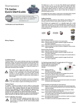
PD200 Smart Valve
Positioner Quick Start
Guide
Environmental Certications
Wiring Diagram
Installation Notes
The PD200 is suitable for use with rotary or linear, single, or double, direct,
or reverse action valve actuators. Depending on the model, the Positioner
will be supplied with a rotary NAMUR adaptor or linkages for linear valve
actuators. Always use sound mechanical practices when mounting the
Positioner.
When fastening the unit to the bracket on the actuator, tighten the fasteners
to a minimum of 11 ft·lbs (15 Nm) of torque after cycling the valve a couple
of times. This allows the shaft to self -center in the pinion slot, or coupler.
Be cautious not to allow undue axial (thrust) load on the shaft.
This product ships with plastic covers installed in the conduit and
pneumatic connection holes to protect the internal components from debris
during shipment and handling. It is the responsibility of the receiving and/
or installation personnel to provide appropriate permanent sealing devices
to prevent the intrusion of debris, or moisture, when stored outdoors or
when installed. It is the responsibility of the installer, or end user, to install
this product in accordance with the National Electrical Code (NFPA 70 or
any other national or regional code dening proper practices.)
Storage
Store the Positioner in a dry indoor environment within a relative humidity
range of 10% to 95% and within a temperature range of -40°F to 149°F (-40°C to
65°C). The Positioner will only support its IP/NEMA ratings when fully installed
with Conduit, conduit plugs and any applicable pneumatic port connections.
Easy Setup (Auto-Calibration)
The PD200 can perform auto-calibration to determine all the parameters of the
valve, such as the open and closed positions and the PID values.
After removing the outer cover, auto-calibration is performed in three easy steps:
1. Press and hold the DOWN arrow key for 5 seconds. The display will
show “FAST PID” then “FULL”.
2. Press the ENTER key and the display will change to “SURE SETUP”.
3. Press the ENTER key again to start the auto-calibration process.
Magnetic Key
The PD200 includes the ability to use a magnetic key to operate the device
locally for convenience or when it is undesirable to remove the outer cover.
The included magnetic key has two sides matching to the North and South
poles of the embedded magnet. Place the black side (North Pole) of the key
against the unit when operating the UP and DOWN arrow selections and
place the green side (South Pole) against the unit when operating the ENTER
selection.
Internal Limit Switch Calibration
The PD200 allows for the setting of Alarm Limit Switches, which are adjusted by
manipulating internal cams to trigger the switch at the specied position.
To adjust these internal cams, rst remove the outer cover by removing the
four corner screws that hold it in place on the positioner body. Once removed,
locate the two screws that fasten the inner cover which includes the display and
control buttons.
Next, remove the black cam lock by pulling on it. Pull off the two cams and
replace them in the desired positions to operate the micro switches. After repo-
sitioning the cams, replace all the covers in reverse order from removal.
The internal limit switches may be modied to act as N/C or N/O by use of a
jumper that is to the left of the left most internal limit switch. Simply position the
jumper to jump either C and N/C or C and N/O, whatever conguration is desired.
Continued:
To reduce risk of death, serious injury or property damage:
• Personnel installing, maintaining, or operang this equipment
must be qualied, must read, understand, and follow these
instrucons before proceeding.
• This document must be retained for future reference.
• Please contact local TopWorx representave for quesons,
claricaons, or comments.
UL Listed General Purpose E359150
Ingress Protection Rating: Type 4X
UL Listed Intrinsically Safe E125326
Ingress Protection rating: Type 4X, IP66
Remove Outer Cover Remove Inner Cover
Cam Lock Upper Cam
Lower Cam

Pneumatic Connection Procedure
Prior to connecting the supply air to the spool valve, ush the system to
remove debris or contaminants. Galvanized pipe can easily ake and
contaminate the system and therefore is not recommended for use with the
PD200. A 50 micron point of use lter is recommended for use with every
device an installation.
Special Conditions of Safe Use
Clean only with a damp cloth to prevent the possibility of electrostatic discharge.
Grounding the positioner is extremely important and highly recommended. Two
grounding points are provided, one internal and one external. If a shielded cable is
utilized, it is recommended to ground the shield at one end only. The non-earthed
end must be carefully insulated.
Connection Specications
About Emerson-TopWorx
Emerson TopWorx is the global leader in valve control and position
sensing for the process industries. Our product solutions manage and
control operations more intelligently and efciently under the most
demanding and extreme industry conditions. The TopWorx portfolio of
proximity sensors, discrete valve controllers, and smart valve positioners
enable automated valve feedback and control and communication via
FOUNDATION Fieldbus, Probus, DeviceNet, AS-Interface, and HART
protocols. They attach to all rotary and linear valves and actuators and
carry a variety of global certications. For more information, please visit
www.topworx.com
Global Locations
The Emerson logo is a trademark and service mark of Emerson Electric Co. ©2022 Emerson
Electric Co . ©2022 TopWorx. All rights reserved. TopWorx, GO Switch, and VIP are all
trademarks of TopWorx. All other marks used in this document are the property of their
respective owners. Information contained herein is subject to change without notice.
ES-09367-1 AC
Americas
3300 Fern Valley Road
Louisville, Kentucky
40213 USA
+1 502 969 8000
Asia-Pacic
1 Pandan Crescent
Singapore 128461
+65 6891 7550
Europe, Middle East, Africa
Horseld Way
Bredbury Industrial Estate
Stockport SK6 2SU United
Kingdom
+44 0 161 406 5155
Electrical Connections
Number of Entry Ports 1
Cable Gland Entry Ports ½ inch NPT female
Pneumatic Connections
Medium Dried, ltered air
Filter Size 50 microns
Operating Pressure 40 to 116 psi (2.8 to 8 bar)
Pneumatic Ports ¼ inch NPT Female
OUT 1
1/4-18 NPT
SUPPLY
1/4-18 NPT
OUT 2²
1/4-18 NPT
Pneumatic Hose Coupling¹
End View of Manifold
Air Filters
Pressure Gauges
0 –160 psi (x2)
Notes
1. Pneumatic hose couplings are not supplied with the positioner.
2. The second OUT port is normally supplied plugged.
NOTICE
-
 1
1
-
 2
2
Ask a question and I''ll find the answer in the document
Finding information in a document is now easier with AI
Related papers
-
 TopWorx PD100 Owner's manual
-
Fisher TopWorx D-Series Quick start guide
-
 TopWorx D-Series Discrete Valve Controllers Owner's manual
-
 TopWorx D Series IOM Owner's manual
-
Fisher T-Series IOM Owner's manual
-
 TopWorx TX-Series Valve Controllers Owner's manual
-
Fisher TopWorx D-Series Asi Interface IOM Owner's manual
-
 TopWorx TX-Series Quick start guide
-
Fisher TopWorx T-Series Quick start guide
-
Fisher TopWorx TVF TVH TVL Quick start guide


