DS1150

Escea DS1150, DS1400, DS1650 Installation guide

  • Hello! I am an AI chatbot trained to assist you with the Escea DS1150 Installation guide. I’ve already reviewed the document and can help you find the information you need or explain it in simple terms. Just ask your questions, and providing more details will help me assist you more effectively!
Installation / Service Instructions
DS 1150, DS1400, DS1650
Gas Fireplace
630358_16
For the latest documentation, visit www.escea.com
Important:
The appliance shall be installed in accordance with;
This installation instruction booklet
Local gas fitting regulations
Municipal building codes
Electrical wiring regulations
Any other relevant statutory regulations
AS/NZS 5601.1:2013 Gas Installations
WARNING:
This appliance must be installed by a qualified person.
DO NOT SPRAY AEROSOLS IN THE VICINITY OF THIS APPLIANCE WHILE IT IS IN
OPERATION.
DO NOT USE OR STORE FLAMMABLE MATERIALS IN OR NEAR THIS APPLIANCE.
DO NOT PLACE ARTICLES ON OR AGAINST THIS APPLIANCE.
DO NOT MODIFY THIS APPLIANCE.
This appliance is not intended for use by young children or infirm persons unless they have been
adequately supervised by a responsible person to ensure that they can use the appliance safely.
Young children should be supervised to ensure that they do not play with the appliance.
Failure to follow these instructions could cause a malfunction of the heater, which could result in
death, serious bodily injury, and/or property damage. Failure to follow these instructions may also
void your fire insurance and/or warranty.
Who can install this product:
Installation must be carried out by a registered installer who, on completion of the installation, must
issue a:
AUS: Certificate of Compliance
NZ: Certificates that comply with the latest legislation in accordance with national and/or local
codes. If these are not issued then the Escea warranty may be void.
Warranty Repair and Annual Servicing:
Please contact Escea if you require warranty work. Warranty repair work must be carried out by a
recognised gas fire technician. It is recommended that recognised Escea Gas Fire Technicians are
also used to carry out annual servicing requirements (particularly during the warranty period). For
contact details of recognised Escea Gas Fire Technicians in your area, or for replacement parts,
please contact the retailer from whom the appliance was purchased our visit our website.
The heater must be installed according to these instructions and in compliance with all relevant:
building, gas fitting, electrical and other statutory regulations (eg. AS/NZS 5601). Any
shortcomings in the appliance and flue installation will be the responsibility of the installer, and
Escea will not be accountable for any such failings or their consequences.
Manufactured by: Escea Ltd, PO Box 5277 Dunedin NZ, Ph: +64 3 478 8220. For contact details
of your local Escea distributor or dealer in New Zealand, please visit: www.escea.com or
email: [email protected]. From Australia, please visit www.escea.com.au, call AU: 1800 460 832 or
WA: 1800 730 140, or email us at [email protected]
DS1150 PRODUCT SPECIFICATION
MODEL NAME
DS1150
Description of Appliance Gas Fire Heater
Star Rating 4.4 Stars
Max. Heat Output 8.2kW
A/NZ Approval No. AS/NZS 5263.1.3:2016
Gas Type Natural Propane ULPG
Gas input
High 34 MJ/hr 34 MJ/hr 34 MJ/hr
Low 25 MJ/hr 25 MJ/hr 25 MJ/hr
Inlet Pressure
Max 5 kPa 5 kPa 5 kPa
Min 1.13 kPa 2.75 kPa 2.75 kPa
Operating Pressure on High 0.68 kPa 1.8 kPa 1.8 kPa
Operating Pressure on Low 0.3 kPa 0.9 kPa 0.9 kPa
Burner Jet Size
LH & RH: 1.5mm
Middle: 1.95mm
LH & RH: 0.85mm
Middle: 1.3mm
LH & RH: 0.85mm
Middle: 1.3mm
Burner Aeration
LH & RH: Closed
Middle: 1 x 3.5mm
LH & RH: 2 x 4mm
Middle: 2 x 12mm
LH & RH: 2 x 7mm
Middle: Spacer
(no restriction)
Pilot injector #37 #27 #27
Appliance Dimensions (mm)
Width 1401mm
Height 788 mm
Depth 350 mm
Weight Kg 130 kg
Ignition System
Electronic Ignition to pilot system
Escea PCB
Ignition Activation 20 secs (approx)
Flame Safeguard Flame Rectication
Consumption 160W @ 0.69A 230V
Remote controls Yes
Timers Yes
Clock Yes
Function lock / child Yes
Temperature control Yes
Connections
Electric 230V AC
Gas 1/2" BSPP female lower centre of replace chassis
Flue Type Aluminium Flexi Flue
Flue Size 75mm and 100mm Flexi Flue & PolyPro
Spigot
Location
Right hand top
Data badge location On Chassis Base
DS1400 PRODUCT SPECIFICATION
MODEL NAME
DS1400
Description of Appliance Gas Fire Heater
Star Rating 5.1 Stars
Max. Heat Output 9.7kW
A/NZ Approval No. AS/NZS 5263.1.3:2016
Gas Type Natural Propane ULPG
Gas input
High 40 MJ/hr 40 MJ/hr 37 MJ/hr
Low 30 MJ/hr 28 MJ/hr 28 MJ/hr
Inlet Pressure
Max 5 kPa 5 kPa 5 kPa
Min 1.13 kPa 2.75 kPa 2.75 kPa
Operating Pressure on High 0.82 kPa 1.98 kPa 1.68 kPa
Operating Pressure on Low 0.4 kPa 0.93 kPa 1.04 kPa
Burner Jet Size
LH & RH: 1.70mm
Middle: 1.95mm
LH & RH: 1.02mm
Middle: 1.3mm
LH & RH: 1.02mm
Middle: 1.25mm
Burner Aeration
LH & RH: 1 x
3.5mm Middle: 1
x 6mm
LH & RH: 2 x 7mm
(identication
grooves present)
Middle: 2 x 13mm
LH & RH: 2 x 8mm
Middle: Spacer
(no restriction)
Pilot injector #37 #27 #27
Appliance Dimensions (mm)
Width 1693 mm
Height 788 mm
Depth 350 mm
Weight Kg 150 kg
Ignition System
Electronic Ignition to pilot system
Escea PCB
Ignition Activation 20 secs (approx)
Flame Safeguard Flame Rectication
Consumption 160W @ 0.69A 230V
Remote controls Yes
Timers Yes
Clock Yes
Function lock / child Yes
Temperature control Yes
Connections
Electric 230V AC
Gas 1/2" BSPP female lower centre of replace chassis
Flue Type Aluminium Flexi Flue
Flue Size 75mm and 100mm Flexi Flue
Spigot
Location
Right hand top
Data badge location On Chassis Base
DS1650 PRODUCT SPECIFICATION
MODEL NAME DS1650
Description of Appliance Gas Fire Heater
Star Rating 5.0 Stars
Max. Heat Output 10.2kW
A/NZ Approval No. AS/NZS 5263.1.3:2016
Gas Type Natural Propane ULPG
Gas input
High 44 MJ/hr 44 MJ/hr 44 MJ/hr
Low 32 MJ/hr 32 MJ/hr 32 MJ/hr
Inlet Pressure
Max 5 kPa 5 kPa 5 kPa
Min 1.13 kPa 2.75 kPa 2.75 kPa
Operating Pressure on High 0.67 kPa 1.67 kPa 1.67 kPa
Operating Pressure on Low 0.34 kPa 0.82 kPa 0.82 kPa
Burner Jet Size
LH & RH: 1.95mm
Middle: 1.95mm
LH & RH: 1.1mm
Middle: 1.2mm
LH & RH: 1.1mm
Middle: 1.2mm
Burner Aeration
All collars (Coals/
Crystalight): Closed
All collars (Logs
and Woodland): 1 x
3.5mm
LH & RH: 2 x 4mm
Middle: 2 x 12mm
LH & RH: 2 x 7mm
Middle: Spacer
(no restriction)
Pilot injector #37 #27 #27
Appliance Dimensions (mm)
Width 1987mm
Height 788 mm
Depth 350 mm
Weight Kg 130 kg
Ignition System
Electronic Ignition to pilot system
Escea PCB
Ignition Activation 20 secs (approx)
Flame Safeguard Flame Rectication
Consumption 160W @ 0.69A 230V
Remote controls Yes
Timers Yes
Clock Yes
Function lock / child Yes
Temperature control Yes
Connections
Electric 230V AC
Gas 1/2" BSPP female lower centre of replace chassis
Flue Type Aluminium Flexi Flue
Flue Size 75mm and 100mm Flexi Flue
Spigot
Location
Right hand top
Data badge location On Chassis Base
A Product Description and Installation Process 8
A1 Product Description 8
A2 Recommended Install Process 8
A3 Product Dimensions 9
B Creating the Cavity 10
B1 Cavity Shape 10
B2 Designing the Cavity 10
B3 Hearth 11
B4 Cavity Base 11
B5 Wall lining 11
B6 Television & Mantel Clearances 11
C Installing the Flue 12
C1 Flue Configuration (If less than 8m flue length is required) 12
C2 Flue Configuration (If more than 8m flue length is required) 14
C3 Installing the Horizontal Powerflue Wall Terminal option 14
C4 Installing the Universal Vertical Powerflue (Internal Install) 17
C5 Installing an Universal Vertical Powerflue (External Install) 19
C6 Installing in Accordance with Relevant Codes 20
C7 Running the Flue 21
C8 Running the Powerflue Electrical Cable 22
D Installing the Electricity and Gas to the Appliance 23
D1 Power Supply 23
D2 Network Cable 23
D3 Gas Pipe Sizing 24
D4 Gas Pipe Position 24
D5 Gas Isolating Valve 25
E Installing the Appliance 26
E1 Connecting the Flue 26
E2 Installation 26
E3 Double Sided Conversion 26
E4 Single Sided Front to Back Conversion (only for single sided fires) 29
E5 Removing (and Replacing) the Glass 30
E6 Remove the Infill & Burners 30
E7 Gas Type Conversion 30
E8 Operating the Appliance 34
E9 Checking the Gas Operating Pressure 34
E10 Auxiliary On/O button 36
E11 Home Automation Setup 37
F Finishing the Installation 38
F1 Coal, Crystalight or Driftwood Fuelbed Installation 38
F2 Log and Woodland Log Fuelbed Retainer Setup 38
F3 Log Fuelbed Installation 39
F4 Woodland Fuelbed Installation 41
F5 Flame Picture 43
F6 Wall Linings 44
F7 Fitting the Bevelled Lite Fascia 45
F8 Locating Wall Mount Cradle for Wireless Control 46
F9 Operating the Appliance 47
F10 Normal Operating Sounds and Smells 48
G Installation Checklist 49
S Service Manual 50
S1 Annual service procedure 50
S2 Error Codes 51
S3 Cleaning the Fuel bed and Glass 53
S4 Cleaning the Fascia 53
S5 Checking Operating Pressure 53
S6 Replacing a Remote Control 53
S7 Replacing the Burners 54
S8 Serial Number 54
S9 Removing or Cleaning Fan 54
S10 Removing the Control Tray 55
S11 Pressure Switch Removal 55
S12 Replacing the Thermal Cut Out (TCO) 56
S13 Servicing the Horizontal/Universal Vertical Powerflue 58
S14 Wiring Diagram 59
B
A C D E F G SERVICE
8
A
Product Description and Installation Process
A1 Product Description
The Escea DS-Series gas fire is a room sealed gas appliance designed to be built into a false cavity. The
appliance is flued using co-linear flexible aluminium flue. The user will control their fire with the Radio
Frequency (RF) remote that will normally be located in its wall mount cradle. In addition to the RF
remote the appliance has a single auxiliary On/O button on the unit. When not in operation it is in a
standby mode unless it is physically isolated from the mains supply.
A2 Recommended Install Process
The following diagram illustrates the steps required to install your gas fire. The sequence in which you
choose to do these tasks will vary depending on your individual scenario. Please read these instructions
fully before proceeding with the installation.
Important: Installations that are not specifically outlined in this manual
should be referred to the Escea Architectural Advisory Team.
Please email [email protected]
i.e. Hutch, under bench, recessed, and joinery enclosed installations.
i.e. Use of heat sensitive materials such as resin stone or laminated timber.
i.e. Flue installations between 8m and 40m.
To ensure that your installation is fully complete, please use the “Installation Checklist” on page 49.
False Cavity Installation
Create the Cavity Install electrical / gas
connections, ue
system, and replace
Finish installation
and t fascia
Section B Section C, D Section F
B
ACDEFGSERVICE
9
A3 Product Dimensions
NOT TO BE MISTAKEN FOR CAVITY DIMENSIONS
All dimensions are in mm.
For more detail, view architectural drawings at www.escea.com or www.escea.com.au
Model A B C D E F G
DS1150 1401 1067 788 408 203 411 350
DS1400 1693 1359 788 408 203 411 350
DS1650 1987 1653 788 408 203 411 350
A
B
C
D
E
F
G
B
A C D E F G SERVICE
10
B
Creating the Cavity
B1 Cavity Shape
The DS Range is suitable for timber framed cavities.
Most existing masonry cavities will not be suitable.
B2 Designing the Cavity
The following aspects must be considered when designing this installation:
Appliance physical size
Single sided or double sided
Wall finishing and interaction with appliance
Positioning of appliance in regards to wall lining (depth into wall)
Use of a fascia - one side or two sides?
Exhaust termination aspect – horizontal / vertical and flue configuration
Flue exhaust fan noise - Is there a direct noise path along the flue, especially for short flue
runs?
Exhaust cowl access for maintenance
Gas pipe layout
Gas isolation valve / pressure test point position
Electrical isolation switch
Home automation network connections - ethernet cable layout
The cavity and wall linings may be constructed from standard timber framing materials and do not need
to be non-combustible.
It is not necessary to line the sides or back of the cavity.
Minimum Framing Dimensions
These DS Series fires are to be installed prior to any wall lining.
The wall lining is the very last task to be completed in this installation.
B
min*
D min*
Side
Single Sided
Side
Double Sided
Front
A
min*
C
min*
*Dimensions shown do not include allowances for
clearance to combustibles to the ue
B
ACDEFGSERVICE
11
Model A B C D
DS1150 364 350 850 1408
DS1400 364 350 850 1700
DS1650 364 350 850 1994
B3 Hearth
A hearth is not required. If a hearth is installed below the fire, it must be at least
100mm below the bottom of the glass or be composed entirely of non-combustible materials.
B4 Cavity Base
This appliance MUST be fully supported on its base, over the entire area of the
underside of the appliance. The base must also be level and strong enough to
support the total product weight, which is approximately 150kg.
The fireplace can be recessed into the ground but must maintain clearances
detailed in the diagram (shown right) for any combustible flooring materials.
NOTE: A recessed floor is required to install the fire with the opening less than
200mm above the floor.
B5 Wall lining
Only after all applicable sections up to section F5 on page 43have been completed is it permissible
to commence with the final wall linings detailed in section F6 on page 44. Wall lining cutout
dimensions around the glass must be adhered to.
Please refer to section F6 on page 44 for wall finishing dimensions surrounding glass.
B6 Television & Mantel Clearances
Television
The diagram (shown right) shows the recommended minimum
clearances for the location of any electrical equipment (such as
Plasma TV, LCD TV or home theatre) above a DS Series gas fire. A
mantel/recess is not required to comply with our recommendation of
TV installation.
NOTE: Dimensions are from the top edge of the glass frame.
NOTE: The television clearance recommendations are to be treated as a
suggestion of a suitable installation only. It is the responsibility of the end
user to check the installation instructions of their electrical appliances to
ensure that the location in relation to the gas fire is suitable. Escea in no
way guarantees or takes responsibility that the recommended installation
suggestion will be suitable for all electrical or home entertainment
appliances.
Mantel
Please refer to the diagram (shown right). Mantels or protruding
ledges above the heater must not be installed lower than the
dimension shown.
NOTE: Dimension are from the top edge of the glass frame.
Fireplace Glass
Fireplace
100mm
Min.
Flooring or Hearth
Fireplace
Fireplace Glass
B
A C D E F G SERVICE
12
C
Installing the Flue
C1 Flue Configuration (If less than 8m flue length is required)
If your flue system is less than 8m long (as shown in diagrams below), then a simple aluminium flexible
flue is required. If you wish to install a longer flue run of up to 40 metres, please contact the Escea
Advisory Team at [email protected].
Horizontally Terminated: Utilises the Escea horizontal power flue enclosure kit.
The horizontal oset of the terminal can be any amount up to the total flue length listed below. Please
consult with Escea’s technical sta if your intended flue configuration falls outside of the bounds of
the flue configurations shown below.
NOTE: When flueing above the fire, the pipe must slope towards fire - NOT towards the terminal. Also when
flueing below the fire, the pipe must slope towards the terminal - NOT towards the fire.
X
Y
X + Y Maximum = 8m
Y Maximum = 1.5m
Y Minimum = 0m
X Maximum = 8m
X Minimum = 0m
X + Y Minimum = 0.4m
8m MAX
Y
X
X + Y = 8m MAX
= 0.4m MIN*
1.2m Co-axial Flue
* Excess noise may be present at this distance
B
ACDEFGSERVICE
13
Vertically Terminated: Utilises the Escea universal vertical power flue enclosure kit.
0.4m Min.
8m Max.
Overall ue length:
8m MAX
1.2m Co-axial Flue
8m MAX
1.2m F-F Liner
UVP Cowl
Vertical PowerFlue
Cowl (Duravent)
Internal
Liner
UVP Unit
8m MAX
1.2m Co-axial Flue
8m MAX
Vertical PowerFlue
Cowl (Duravent)
External
B
A C D E F G SERVICE
14
C2 Flue Configuration (If more than 8m flue length is required)
If your flue system is greater than 8m long (up to 40m long), then please contact the Escea Advisory
Team at [email protected] for further guidelines.
C3 Installing the Horizontal Powerflue Wall Terminal option
The horizontal powerflue wall terminal must be installed in the correct
orientation (the small horizontal slot should be at the bottom). This
allows for the correct operation of the flue system and prevents the
ingress of water.
The horizontal powerflue wall terminal must be weather-tight when
installation is complete to prevent damage to the dwelling. It must be
installed by a suitably qualified person.
Fit the horizontal powerflue wall terminal into the hole and fix in place, making sure the installation is
sealed appropriately to prevent the ingress of water from outside the wall cladding. Take notice of the
label on the termination which shows the correct orientation of the terminal.
Note: It is the responsibility of the installer to ensure the horizontal powerflue wall terminal is installed to all
relevant building codes to ensure weather tightness.
B
ACDEFGSERVICE
15
Creating the Hole in the Outside Wall
When cutting the hole in the outside wall, be mindful of how the installation of
the horizontal powerflue wall terminal will be finished; the installation must be
weatherproof.
Ideal Hole/Cavity Size for Horizontal Powerflue
Without Side Brackets With Side Brackets
X 298mm 360mm
Y 298mm 298mm
Z 175mm Excluding allowance for flue which exits here
The horizontal powerflue wall terminal can be attached to the wall in two ways:
A) From the front of the terminal:
B) By attaching the optional wall terminal installation brackets to the sides of the cavity and attaching
the horizontal powerflue wall terminal to these, from the front:
Attach the Ø100mm and Ø75mm flexible aluminium flues to the spigots on the rear of the horizontal
powerflue wall terminal using the hose band clamps supplied. Plug the powerflue electrical cable into
the back of the horizontal powerflue wall terminal.
Ensure that the electrical cable is firmly secured to the wall terminal or building to prevent damage or
disconnection if pulled.
B
A C D E F G SERVICE
16
Fit the horizontal powerflue wall terminal into the hole and fix it in place, making sure the installation is
sealed appropriately to prevent the ingress of water from outside the wall cladding.
Note: It is the responsibility of the installer to ensure the horizontal powerflue wall terminal is installed to
all relevant building codes to ensure weather tightness. This may necessitate the use of appropriate flashing
material where appropriate.
IMPORTANT: Ensure that flashings do not restrict the air intake slot around the periphery of the
cowl.
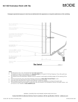
How to Flash the Horizontal Powerflue
The following diagrams are excerpts from the Escea architect drawings and are available in full on our
website. These diagrams are recommendations, and your installation must comply with any local or
national building codes.
Head and Sill scale 1:5
Jamb scale 1:5
framing member with
wall wrap and flashing
tape over
cladding on cavity
batten
typical head flashing with
stop ends to comply with
relevant building code
horizontal powerflue
unit
terminal fixing brackets
(shown dashed) fixed
to framing
flashing tape over wall
wrap to opening
seal air gap to opening
terminal screw fixed to flange
with flange fixed to studs at
fixing brackets
packer to lift terminal off
sill
sill cover to cladding to comply
with relevant building code
300 min
360 min
10
cladding on cavity
batten
10
horizontal powerflue
unit
terminal screw fixed to flange
with flange fixed to studs at
fixing brackets
terminal fixing
brackets screw fixed
into framing
framing member with
wall wrap and flashing
tape over
continuous sealant strip
to jambs
scriber or plug may be
required - dependent on
cladding type
seal air gap to opening
cowl
198
138 60
scale: date:
ecn:
drawn:
drawing no:
revision:file:
Horizontal Powerflue Detail
as shown ECN-2155 EDA-0006 MGD-Series FLUE Master File.dwg
V. 02 08.12.2017
Head and Sill scale 1:5
Jamb scale 1:5
framing member with
wall wrap and flashing
tape over
cladding on cavity
batten
typical head flashing with
stop ends to comply with
relevant building code
horizontal powerflue
unit
terminal fixing brackets
(shown dashed) fixed
to framing
flashing tape over wall
wrap to opening
seal air gap to opening
terminal screw fixed to flange
with flange fixed to studs at
fixing brackets
packer to lift terminal off
sill
sill cover to cladding to compl
y
with relevant building code
300 min
360 min
10
cladding on cavity
batten
10
horizontal powerflue
unit
terminal screw fixed to flange
with flange fixed to studs at
fixing brackets
terminal fixing
brackets screw fixed
into framing
framing member with
wall wrap and flashing
tape over
continuous sealant strip
to jambs
scriber or plug may be
required - dependent on
cladding type
seal air gap to opening
cowl
198
138 60
scale: date:
ecn:
drawn:
drawing no:
revision:file:
Horizontal Powerflue Detail
as shown ECN-2155 EDA-0006 MGD-Series FLUE Master File.dwg
V. 02 08.12.2017
B
ACDEFGSERVICE
17
C4 Installing the Universal Vertical Powerflue (Internal Install)
Note: For information regarding an external install of the UVP, go to section C5 on
page 19.
The Universal Vertical Powerflue (UVP) internal configuration is designed to
have the fan, mounted within the roof space of the house, and the vertical
Ø225mm diameter liner, containing a Ø100mm flexi, penetrate through
the roof. The UVP internal conversion kit comes with a 1200mm liner that is
specific to the internal installation and must always be used.
Note: The flue setup must comply with either section C1 on page 12 or C2 on
page 14.
Use standard methods to flash the roof penetration. The installation must be
weatherproof and conform to all local council standards including powered flue
termination rules.
Mount the fan mount bracket (1) to the roof framing and strapping using
timber ensuring that the flue is rigid and vertical. Ensure that the mounting
timber does not obstruct access to the 3xM5 screw threads on the side of the
fan unit.
Aim to have the fan enclosure (2) mounted as high as possible, mainly to allow
sucient fall for condensation drainage if the flexi-flue is to run horizontally.
Ensure there is sucient space below fan enclosure (2) to have access to fit the
flexi-flue tubes (3) and allow flowing bends if required.
Note: The UVP-Internal and the flexi flue connections must be installed in
a location accessible for service or replacement; a service hatch or removable
flashing to allow access may be required.
Note: When installing the unit onto a flue liner, ensure the length of flue liner above the roof is the minimum
required length. ENSURE the Ø25mm restriction plate is installed on the inlet.
290
229.1
ø226.8
31.6
221.8
250.2
31.6
103.4
TIMBER MUST NOT
OBSTRUCT THESE ZONES
Head and Sill scale 1:5
Jamb scale 1:5
framing member with
wall wrap and flashing
tape over
cladding on cavity
batten
typical head flashing with
stop ends to comply with
relevant building code
horizontal powerflue
unit
terminal fixing brackets
(shown dashed) fixed
to framing
flashing tape over wall
wrap to opening
seal air gap to opening
terminal screw fixed to flange
with flange fixed to studs at
fixing brackets
packer to lift terminal off
sill
sill cover to cladding to compl
y
with relevant building code
300 min
360 min
10
cladding on cavity
batten
10
horizontal powerflue
unit
terminal screw fixed to flange
with flange fixed to studs at
fixing brackets
terminal fixing
brackets screw fixed
into framing
framing member with
wall wrap and flashing
tape over
continuous sealant strip
to jambs
scriber or plug may be
required - dependent on
cladding type
seal air gap to opening
cowl
198
138 60
scale: date:
ecn:
drawn:
drawing no:
revision:file:
Horizontal Powerflue Detail
as shown ECN-2155 EDA-0006 MGD-Series FLUE Master File.dwg
V. 02 08.12.2017
B
A C D E F G SERVICE
18
The UVP-Internal kit is intended for use within an accessible roof space or ‘chimney’ construction.
Service access must be provided.
Ensure installation complies with relevant building codes and regulations
To appliance
Typical Installation UVP Cowl
‘Decktite’ or similar ashing
1.2m F-F Liner
Hose band clamps
Ø75mmØ100mm
Ensure Power Flue unit
is securely braced using
integral brackets.
Roof Space
Power cord to
appliance
UVP Fan Unit
B
ACDEFGSERVICE
19
C5 Installing an Universal Vertical Powerflue (External Install)
Note: For information regarding an internal install of the UVP, go to section C4 on page 17.
The UVP is designed to have the enclosure containing the fan unit mounted externally.
The cowl surround should be fixed in place as shown.
Mount the UVP kit to the top of a chimney flashing plate or penetrate the roof with an optional flue
liner accessory and fit the UVP kit over the flue liner, sealing the penetration with a decktite or similar
flashing. Ensure the terminal is vertical and rigidly mounted, the flexi flue attached below is fixed to
the terminal spigots using the supplied hose clamps. The flexi flue is held in place by drilling 3 holes and
screwing 3 self tapping screws evenly around each hose band clamp (as shown in the picture below).
Note: When installing the unit onto a flue liner, ensure the length of flue liner above the roof is the minimum
required length. ENSURE the Ø25mm restriction plate is installed on the inlet.
B
A C D E F G SERVICE
20
C6 Installing in Accordance with Relevant Codes
The location of the horizontal powerflue wall terminal must be installed in accordance with AS/NZS
5601 and any other relevant building codes. If possible, avoid installing the horizontal powerflue wall
terminal in areas exposed to high winds and extreme weather.
Some of the minimum clearances for a fan assisted wall terminal are listed below; please refer to
AS/NZS 5601 Gas installation standard for full guidance on the design of the flue system. Where
possible allow a greater clearance.
A Below eaves, balconies and other projections 200mm
B From the oor, above a balcony or other surface 300mm
C From a return wall or external corner 300mm
D From a gas meter or regulator vent 1000mm
E From electricity meter or fuse box 500mm
F From a drain pipe or soil stack 75mm
G Horizontally from any building structure or obstruction 500mm
H From any other ue terminal or combustion air intake 300mm
J Horizontally from any moving window, door, non-mechanical air inlet, or any other
opening into a building with the exception of sub oor ventilation
300mm
K From a mechanical air inlet or spa blower 1000mm
L Vertically below any moving window, door, non-mechanical air inlet, or any other
opening into a building with the exception of sub oor ventilation
300mm
N Horizontally from a roof light 600mm
O Vertically from a roof light 500mm
Q Vertically from a flat roof 500mm
R Horizontally from a vertical structure 500mm
S Below a roof window 2000mm
T Above or either side of a roof window 600mm
U From a dormer window 1500mm
V Above the apex of the roof (see note 1 on following page) 300mm
W From an open flue 1500mm
N
R
F
S
W
U
A
V
K
Q
E
J
J
A
H
E
D
C
C
A
O
G
J
L
B
M
P
Prohibited area for ues is
below or Distance 'E' to
the left and right of the
Electricity meter
or fuse box
M = Gas Meter
P = Electricity meter or Fuse box
H
/