Page is loading ...

P/N: 600C002605010
ADE-6050
Intel Core Duo/Solo
945GM Mini ITX Board
User’s Manual
Rev. 1.0
2007/1/8

ADE-6050 User’s Manual
2 / 48
Copyright
All rights reserved. The information contained in this guide has been validated and
reviewed for accuracy. No patent liability is assumed with respect to the use of the
information contained herein. While every precaution has been taken in the preparation of
this guide, the Manufacturer assumes no responsibility for errors or omissions.
No part of this publication may be reproduced, stored in a retrieval system, or transmitted in
any form or by any means, electronic, mechanical, photocopying, recording, or otherwise,
without the prior written permission of Manufacturer.
Trademark
Intel
®
, Pentium
®
and Celeron
®
are registered trademarks of Intel
®
Corporation.
Microsoft
®
and Windows
®
are registered trademarks of Microsoft Corporation.
All products and company names are trademarks or registered trademarks of their
respective holders.
These specifications are subject to change without notice.
Technical Support
We hope you to get the maximum performance from your products and be willing to help if
running into technical difficulties. For the most frequently asked questions, it’s easily found
answers from the product documentation and usually a lot more detailed, so please take
reference to this manual first. If the answer still can not be found, gather all the information
or questions applying to the problem, and with the product on hand, contact your distributor,
sales representative, or customer service center for technical support. Most problems
reported are minor and able to be easily solved over the phone. In addition, free technical
support is available and always ready to give advices on application requirements or
specific information on the installation and operation of any of our products.
Please have the following information ready before you call:
1. Product name and serial number
2. Description of your peripheral attachments
3. Description of your software (operating system, version, application software, etc.)
4. A complete description of the problem
5. The exact wording of any error messages

ADE-6050 User’s Manual
3 / 48
How to Use This Manual
This manual is written for the system integrator, PC technician and knowledgeable PC end
user. It describes how to configure your system board to meet various operating
requirements. The user’s manual is divided into four chapters, with each chapter
addressing a basic concept and operation of the server board.
Chapter 1: Introduction - presents what you have inside the box and gives you an
overview of the product specifications and basic system architecture for the system board.
Chapter 2: Hardware Configuration Setting - shows the definitions and locations of
Jumpers and Connectors so that you can easily configure your system.
Chapter 3: System Installation - describes how to properly mount the CPU and main
memory for a safe installation. It will also introduce and show you the driver installation
procedure for the Graphics Controller and Ethernet Controller.
Chapter 4: BIOS Setup Information - specifies the meaning of each setup parameter, how
to get advanced BIOS performance.

ADE-6050 User’s Manual
4 / 48
Table of Content
1. Introduction..........................................................................................................................8
1.1 Description.......................................................................................................................8
1.2 Packing Check List.........................................................................................................9
1.3 Specifications................................................................................................................10
1.4 System Architecture.....................................................................................................12
1.5 Dimensions.....................................................................................................................13
2. Hardware Configuration Setting.............................................................................15
2.1 Board Layout..................................................................................................................16
2.2 Jumpers & Connectors...............................................................................................17
2.3 Jumpers- Setting & Connectors description.........................................................18
2.3.1 LCD power setting select: JP1..............................................................................18
2.3.2 Clear CMOS setting select: JP2...........................................................................18
2.3.3 Auto power on select: JP3.....................................................................................18
2.3.4 BIOS write protection setting: JP4........................................................................18
2.3.5 Audio connector: CN1 ............................................................................................18
2.3.6 COM2/1 RS232 connectors: CN2 ........................................................................18
2.3.7 PS/2 mouse & keyboard connectors: CN3 .........................................................18
2.3.8 VGA / DVI Connector: CN4 ...................................................................................18
2.3.9 LAN 1 + USB 0/1 & LAN 2 + USB 2/3 Connectors: CN6 & CN5.....................19
2.3.10 Internal USB 4/5 & 6/7 Connectors: CN12 & CN11...........................................19
2.3.11 External K/B & M/S Connector: CN7 ...................................................................19
2.3.12 CD-In Connector: CN8 ...........................................................................................19
2.3.13 Line out Connector: CN9 .......................................................................................20
2.3.14 LVDS Connector: CN10.........................................................................................20
2.3.15 System Fan Connector: CN14..............................................................................20
2.3.16 CPU Fan Connector: CN15...................................................................................20
2.3.17 ATX power Connector: CN16................................................................................20
2.3.18 COM3 / COM4 Connectors: CN18/CN19............................................................20
2.3.19 8-bit Digital I/O Connector: CN20.........................................................................21
2.3.20 Front Panel Connector: CN21...............................................................................21
2.3.21 Primary IDE Connector: IDE1...............................................................................21
2.3.22 Serial ATA Connectors: SATA1, SATA2...............................................................21

ADE-6050 User’s Manual
5 / 48
3. System Installation.........................................................................................................23
3.1 Socket 478 Processors................................................................................................23
3.1.1 Installing CPU..........................................................................................................23
3.2 Installing Cooling Fan..................................................................................................23
3.3 Main Memory..................................................................................................................24
3.4 Installations....................................................................................................................24
4. BIOS Setup..........................................................................................................................26
4.1 Entering Setup...............................................................................................................26
4.2 Main Menu.......................................................................................................................26
4.2.1 Standard CMOS Features .....................................................................................27
4.2.2 Advanced BIOS Features......................................................................................28
4.2.3 Advanced Chipset Features..................................................................................33
4.2.4 Integrated Peripheral..............................................................................................36
4.2.5 Power Management Setup....................................................................................41
4.2.6 PnP/PCI/PCI-E Configurations .............................................................................44
4.2.7 PC Health Status.....................................................................................................45
4.2.8 Load Fail-Safe Default............................................................................................46
4.2.9 Load Optimized Defaults........................................................................................46
4.2.10 Supervisor/User Password Setting ......................................................................47
4.2.11 Exit Selecting ...........................................................................................................48

ADE-6050 User’s Manual
6 / 48

ADE-6050 User’s Manual
7 / 48
CHAPTER 1

ADE-6050 User’s Manual
8 / 48
1. Introduction
1.1 Description
The ADE-6050 all-in-one Mini-ITX is designed to fit a high performance Intel Core
TM
Duo
based processor and compatible for high-end computer system applications with PCI bus
architecture to meet today’s demanding pace and keep complete compatibility with
hardware and software designed. The onboard devices support one PCI Express x1 and
one PCI slot, integrated graphics, and onboard dual Marvell Gigabit Ethernet controllers.
It’s beneficial to build up a high performance and high data availability system for VARs, or
system integrators.
The ADE-6050 supports Intel Core
TM
Duo socket M processors built Intel 945GM and
ICH7M chipset integrated GMA 950 graphics with DVMT 3.0 display memory up to 224 MB
for dual display function by VGA/LVDS, VGA/DVI, and DVI/LVDS. The board supports two
SODIMMs up to 2 GB with dual channel DDR2 533/667, enhanced onboard one PCI-IDE
interface supporting one drive up to PIO mode 4 timing and Ultra ATA 33/66/100
synchronous mode feature, one CF socket interface, and two SATAII high-speed data
transferring at up to 3 GB/s, integrated Realtek ALC655 AC97 codec. The onboard Super
I/O chipsets support four serial ports: two RS-232 serial port interfaces and two RS-232 pin
headers, Hardware Monitor function, eight Hi-speed USB 2.0 ports offering up to 40X
greater bandwidth over USB 1.1, and two 6-pin Mini-DIN connectors for PS/2 mouse and
keyboard. Besides, high precision Real Time Clock built to support Y2K for accurate
scheduling and storing configuration information, one 20-pin standard connector designed
to support ATX power function, and a feature of CPU overheat protection will provide user
more security and stability.
Target for key embedded applications such as Point of Sales (POS), automated KIOSKs,
medical instruments, advanced automation for buildings and homes, and gaming machines.
All of these features make ADE-6050 excellent in all-in-one applications.

ADE-6050 User’s Manual
9 / 48
1.2 Packing Check List
The ADE-6050 package includes the following basic items accompany with this manual.
Ø One Mini ITX ADE-6050 SBC
Ø One Installation Guide for ADE-6050
Ø One 40-pin IDE cable
Ø One Serial ATA cable
Ø One USB cable
Ø One Serial port for RS232 cable
Ø One I/O Shield cover
Ø One Supporting CD Driver contains internal VGA display driver, Ethernet network
controller driver and on board devices drivers
If any of these items is damaged or missed, please contact your vendor and save all
packing materials for future replacement and maintenance.

ADE-6050 User’s Manual
10 / 48
1.3 Specifications
System
CPU
Intel
®
Core™ Duo / Solo and Celeron
®
M processor (Yonah Core)
Intel
®
Core™ 2 Duo Mobile processor on Napa refresh (Merom/Socket M)
FSB FSB 533/667 MHz
BIOS Award BIOS with 4 Mb Flash ROM
System Chipset Intel
®
945GM + ICH7M
I/O Chip ITE
®
IT8712F
System Memory
2 x 200-pin SODIMM sockets support dual-channel DDR2 533/667
SDRAM up to 2GB
Storage
1 x Ultra DMA33 supports two IDE devices by 40-Pin IDE connector,
2 x Serial ATA connectors high-speed data transfer at up to 300 MB/s
SSD 1 x CompactFlash™ Type I/II Socket
Watchdog Timer Reset: 1 sec.~255 min. and 1 sec. or 1 min./step
H/W Status Monitor
Monitoring system temperature, voltage, and cooling fan status.
Auto throttling control when CPU overheats.
MIO
Internal I/O 2 x RS-232, 4 x USB 2.0, 1 x IrDA, 1 x external KB/MS
Rear I/O
1 x KB/MS, 1 X VGA, 1 x DVI, 2 x RS-232, 2 x LAN, 4 x USB,
1 x Audio Jack
Display
Chipset Intel
®
945GM + ICH7M
Display Memory Intel
®
DVMT 3.0 supports up to 224 MB video memory
Resolution
Analog Display : up to 2048 x 1536 @ 75MHz video memory(QXGA)
Digital LVDS : up to 2048 x 1536 (QXGA)
VGA/LCD Interface DSUB-15 & DVI connectors
LVDS Dual Channel (2 x 18-bit) LVDS
DVI Chrontel
®
CH7307 DVI transmitter

ADE-6050 User’s Manual
11 / 48
Audio
AC97 Codec Realtek
®
ALC655 5.1CH 3D audio codec
Audio Interface Line in, Line out, Mic in by jack, CD-in by pin header
Ethernet
Chipset Dual Marvell
®
88E8053 PCI-E Gigabit Ethernet controllers
Ethernet Interface IEEE 802.3 10/100/1000 BASE-TX
Mechanical & Environmental
Power Requirement [email protected], [email protected], [email protected]. [email protected]
Power Type 20-pin ATX power connector
Operating Temperature 0~60°C (32~140°F)
Operating Humidity 0%~90% relative humidity, non-condensing
Size (L x W) 6.69" x 6.69" (170 mm x 170 mm)
Weight 0.94lbs (430g)

ADE-6050 User’s Manual
12 / 48
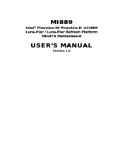
1.4 System Architecture
All of details operating relations are shown in ADE-6050 system block diagram.
Micro FCPGA
for Intel CoreDuoSolo
Processor
CK-410M
IMVP6
GMCH (945GM)
1466 FCBGA
ICH7M
652 mBGA
DDR2SODIMM
533/667 X2
CRT & LCD
Super I/O
IT8712F
ATA100
USB2.0
Keyboard
Mouse
COM 1 / 2
PCI BUS
LVDS
&
VGA
533/667 MHz FSB
AC97 Audio Codec
SATAII
Super I/O
IT8712F
COM 3 / 4
DVI
Marvell 88E8053x2
10/100/1000 Base-TX
PCI-E BUS
DMIBus
PCISLOT
FWH
IDE Primary
USB Port 1/2/3/4
USB Port 5/6/7/8
SATAPort12
DigitalIO
PCIEby1SLOT

ADE-6050 User’s Manual
13 / 48
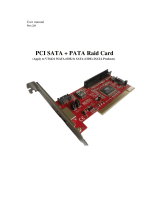
1.5 Dimensions
33.0
10.2
132.1
6
.
2
1
6
3
.
7
1
7
0
170
10.51
0
39.5
78.51
106.17
128.61
146.35
6.5 22.0
35.5
G G
Unit: mm

ADE-6050 User’s Manual
14 / 48
CHAPTER 2

ADE-6050 User’s Manual
15 / 48
2. Hardware Configuration Setting
This chapter gives the definitions and shows the positions of jumpers, headers and
connectors. All of the configuration jumpers on the board are in the proper position. The
default settings shipped from factory are marked with an asterisk («).
In general, jumpers on the board are used to select options for certain features. Some of
the jumpers are designed to be user-configurable, allowing for system enhancement. The
others are for testing purpose only and should not be altered. To select any option, cover
the jumper cap over (SHORT) or remove (NC) it from the jumper pins according to the
following instructions. Here, NC stands for “Not Connect”.

ADE-6050 User’s Manual
16 / 48
2.1 Board Layout
CN12
CN2
CN8
CN11
95P08
EXT. KB/MS
KB/MS
COM1
USB45USB67
LVDS-CONN
LINEOUT
CN3
CN4
CRT
DVI
CN7
COM2
CN6CN5
CN1
AUDIO
CN9
SATA2
SATA1
IDE1
P
C
I
1
P
C
I
E
X
1
CN18
COM3
CN19
COM4
CF
CN20
CN21
JP2
JP4
CN14
CN15
CN16
JP3
DIMM1
DIMM2
CN10
JP1
LINEOUT
CDIN
LAN2USB23 LAN1USB01
ATXPOWER

ADE-6050 User’s Manual
17 / 48
2.2 Jumpers & Connectors
JUMPERS FUNCTION REMARK
JP1
LVDS power select 1 x 3 header
JP2
Clear CMOS select 1 x 3 header
JP3
Auto power on select 1 x 2 header
JP4
BIOS write protection select 1 x 3 header
CONNECTORS
FUNCTION REMARK
CN1
Audio connector
CN2
COM1/2 RS232 serial port connectors
CN3
PS/2 mouse & keyboard connectors
CN4
D-sub 15-pin VGA & DVI 24-pin connectors
CN5
USB 2, 3 & LAN 2 connectors
CN6
USB 0, 1 & LAN 1 connectors
CN7
External keyboard & mouse connector 1 x 6 wafer
CN8
CD-In connector 1 x 4 header
CN9
Line out connector 1 x 4 wafer
CN10
LVDS connector HIROSE
CN11
Internal USB connector 6 & 7 2 x 5 header
CN12
Internal USB connector 4 & 5 2 x 5 header
CN14
System fan connector 1 x 3 wafer
CN15
CPU fan connector 1 x 3 wafer
CN16
ATX power connector 2 x 10 connector
CN18
COM3 RS-232 serial port pin-header 2 x 5 header
CN19
COM4 RS-232 serial port pin-header 2 x 5 header
CN20
8-bit Digital I/O pin-header 2 x 5 header
CN21
Front panel connector 2 x 13 header
IDE1
Primary IDE connector 2 x 20 header
SATA1, SATA2
Serial ATA1/2 connectors
CFII
Type II CompactFlash™ connector
DIMM1/2
200-pin DDR2 SODIMM sockets
PCI
PCI slot
PCIEX1
PCI-E by 1 slot

ADE-6050 User’s Manual
18 / 48
2.3 Jumpers- Setting & Connectors description
2.3.1 LCD power setting select: JP1 2.3.2 Clear CMOS setting select: JP2
PIN No. Description
1-2 3.3V«
2-3 5V
PIN No. Description
1-2 Normal operation «
2-3 Clear CMOS
2.3.3 Auto power on select: JP3 2.3.4 BIOS write protection setting: JP4
PIN No. Description
1-2 Auto power on
Open Disabled«
PIN No. Description
1-2 Write-protection (Default) «
2-3 Disable
2.3.5 Audio connector: CN1 2.3.6 COM2/1 RS232 connectors: CN2
PIN No. Description
Blue Line-in
Green Speaker out
Pink MIC-in
PIN No.
Description PIN No.
Description
1
DCD
6
DSR
2
RXD
7
RTS
3
TXD
8
CTS
4
DTR
9
RI
5
Ground
2.3.7 PS/2 mouse & keyboard connectors: CN3
PS/2 Mouse
PIN No. Description
1 Mouse data
2 NC
3 Ground
4 +5V
5 Mouse clock
6 NC
PS/2 Keyboard
PIN No. Description
1 Keyboard data
2 NC
3 Ground
4 +5V
5 Keyboard clock
6 NC
2.3.8 VGA / DVI Connector: CN4
VGA
PIN No. Description
PIN No. Description
1
Red Signal
9
+5V
2
Green Signal
10
Ground
3
Blue Signal
11
NC
4
NC
12
DCC_DATA
5
Ground 13 HSYNC
6
Ground 14 VSYNC
7
Ground 15 DCC_CLK
8
Ground
DVI
PIN No.
Description PIN No.
Description
1
TDC2#
13
NC
2
TDC2
14
DVI_5V
3
GND
15
GND
4
NC
16
DVI_DET
5
NC
17
TDC0#
6
SC_DDC
18
TDC0
7
SD_DDC
19
GND
8
NC
20
NC
9
TDC1#
21
NC
10
TDC1
22
GND
11
GND
23
TLC
12
NC
24
TLC#

ADE-6050 User’s Manual
19 / 48
2.3.9 LAN 1 + USB 0/1 & LAN 2 + USB 2/3 Connectors: CN6 & CN5
LAN 1/2
PIN No.
Description PIN No.
Description
1 MDI0+ 5 MDI2+
2 MDI0- 6 MDI2-
3 MDI1+ 7 MDI3+
4 MDI1- 8 MDI3-
USB 0/1/2/3
PIN No.
Description PIN No.
Description
1 +5 V (fused) 5 +5 V (fused)
2 USBP0-/2- 6 USBP1-/3-
3 USBP0+/2+ 7 USBP1+/3+
4 Ground 8 Ground
2.3.10 Internal USB 4/5 & 6/7 Connectors: CN12 & CN11
Description
PIN No. PIN No. Description
VCC 1 2 VCC
USBP4-/6- 3 4 USBP5-/7-
USBP4+/6+
5 6 USBP5+/7+
Ground 7 8 Ground
NC 9 10 NC
Note :
1) If you are using a USB 2.0 device with Windows
2000/XP, you will need to install the USB 2.0 driver
from the Microsoft
®
website. If you are using Service
pack 1 (or later) for Windows
®
XP, and using Service
pack4 (or later) for Windows
®
2000, you will not have
to install the driver.
2.3.11 External K/B & M/S Connector: CN7 2.3.12 CD-In Connector: CN8
PIN No. Description
1 MS Clock
2 MS Data
3 KB Clock
4 KB Data
5 Ground
6 VCC
PIN No. Description
1 CD-L
2 CD-Ground
3 CD-Ground
4 CD-R

ADE-6050 User’s Manual
20 / 48
2.3.13 Line out Connector: CN9 2.3.14 LVDS Connector: CN10
PIN No. Description
1 LOUT_L
2 Ground
3 Ground
4 LOUT_R
Description
PIN
No.
PIN
No.
Description
NC 2 1 NC
Ground 4 3 Ground
LVDS_YAM1 6 5 LVDS_YAM0
LVDS_YAP1 8 7 LVDS_YAP0
Ground 10 9 Ground
LVDS_CLKAM
12 11 LVDS_YAM2
LVDS_CLKAP
14 13 LVDS_YAP2
Ground 16 15 Ground
LVDS_YBM0 18 17 NC0
LVDS_YBP0 20 19 NC
Ground 22 21 Ground
LVDS_YBM2 24 23 LVDS_YBM1
LVDS_YBP2 26 25 LVDS_YBP1
Ground 28 27 Ground
NC 30 29 LVDS_CLKBM
NC 32 31 LVDS_CLKBP
+12V 34 33 NC
+12V 36 35 NC
VCC_LCD 38 37 NC
VCC_LCD 40 39 LCD_BKL
Signal
Type
Description
LDDC_CLKL
I/O
EDID support for flat panel display
LDDC_DATAL
I/O
EDID support for flat panel display
2.3.15 System Fan Connector: CN14 2.3.16 CPU Fan Connector: CN15
PIN No. Description
1 Ground
2 +12V
3 Fan Speed Control
PIN No. Description
1 Ground
2 +12V
3 Fan Speed Control
2.3.17 ATX power Connector: CN16 2.3.18 COM3 / COM4 Connectors: CN18/CN19
PIN No.
Description PIN No.
Description
1 +3.3V 11
+3.3V
2 +3.3V 12
-12V
3 Ground 13
Ground
4 +5V 14
PS-ON
5 Ground 15
Ground
6 +5V 16
Ground
7 Ground 17
Ground
8 NC 18
-5V
9 5VSB 19
+5V
10 +12V 20
+5V
Description
PIN
No.
PIN
No.
Description
DCD
1
2
DSR
RXD
3
4
RTS
TXD
5
6
CTS
DTR
7
8
RI
Ground
9
10
V
CC
/