
PCI-6886
PCI Intel
®
Celeron
®
M 600MHz
0L2 Half-sized SBC with VGA/
LVDS/LAN/USB2.0/SATA and
SDD
User’s Manual

PCI-6886 User’s Manual ii
Copyright
This document is copyrighted, © 2005. All rights are reserved. The origi-
nal manufacturer reserves the right to make improvements to the products
described in this manual at any time without notice.
No part of this manual may be reproduced, copied, translated or transmit-
ted in any form or by any means without the prior written permission of
the original manufacturer. Information provided in this manual is
intended to be accurate and reliable. However, the original manufacturer
assumes no responsibility for its use, nor for any infringements upon the
rights of third parties that may result from such use.
Acknowledgements
Award is a trademark of Award Software International, Inc.
VIA is a trademark of VIA Technologies, Inc.
IBM, PC/AT, PS/2 and VGA are trademarks of International Business
Machines Corporation.
Intel and Pentium are trademarks of Intel Corporation.
Microsoft Windows® is a registered trademark of Microsoft Corp.
RTL is a trademark of Realtek Semi-Conductor Co., Ltd.
ESS is a trademark of ESS Technology, Inc.
UMC is a trademark of United Microelectronics Corporation.
SMI is a trademark of Silicon Motion, Inc.
Creative is a trademark of Creative Technology LTD.
All other product names or trademarks are properties of their respective
owners.
For more information on this and other Advantech products, please visit
our websites at: http://www.advantech.com
http://www.advantech.com/epc
For technical support and service, please visit our support website at:
http://service.advantech.com.tw/eservice/
This manual is for the PCI-6886.
Part No.200K688610
1st Edition, Mar, 2005

iii
Packing List
Before you begin installing your card, please make sure that the following
materials have been shipped:
• 1 PCI-6886 all-in one single board computer
• 1 startup manual
• 1 CD-ROM or disks for utility, drivers, and manual (in PDF format)
• 1 power cable p/n:1700000265
• 1 Y cable for PS/2 Keyboard, PS/2 Mouse p/n:1700060202
• 1 FDD cable(600mm) p/n:1701340603
• 1
Parallel port cable p/n:17002600250
• 1 EIDE (HDD) cable p/n:1701400452
• 1 ATX feature cable p/n: 1700001276
• Mini Jumper p/n:1653302122
If any of these items are missing or damaged, contact your distributor or
sales representative immediately.
Optional Items:
• 1701140201 COM2 cable (2.00mm)
• 1700001166 COM3&COM4 cable with bracket (2.00mm)
• 1703100260 USB cable adapter (2.00mm)
• CF-HDD-ADP CompactFlash 50-pin to IDE 44-pin adapter
• PCM-231A-00A1 Audio module with Line-in, Line-out, mic

PCI-6886 User’s Manual iv
Model No. List Description
PCI-6886F-M0A1 PCI Celeron M 600M 0L2 Slot PC
W/852GM
PCI-6886FG-M0A1 PCI Celeron M 600M 0L2 Slot PC
W/852GM,Giga LAN
Additional Information and Assistance
Visit the Advantech web site at www.advantech.com where you can find
the latest information about the product.
Step 1. Contact your distributor, sales representative, or Advantech's cus-
tomer service center for technical support if you need additional
assistance. Please have the following information ready before
you call:
• Product name and serial number
• Description of your peripheral attachments
• Description of your software (operating system, version, application
software, etc.)
• A complete description of the problem
• The exact wording of any error messages

v
FCC
This device complies with the requirements in
part 15 of the FCC rules: Operation is subject to
the following two conditions:
1.This device may not cause harmful interfer-
ence, and
2. This device must accept any interference
received, including interference that may cause
undesired operation
This equipment has been tested and found to
comply with the limits for a Class A digital device,
pursuant to Part 15 of the FCC Rules. These lim-
its are designed to provide reasonable protection
against harmful interference when the equipment
is operated in a commercial environment. This
equipment generates, uses, and can radiate
radio frequency energy and, if not installed and
used in accordance with the instruction manual,
may cause harmful interference to radio commu-
nications. Operation of this device in a residential
area is likely to cause harmful interference in
which case the user will be required to correct
the interference at his/her own expense. The
user is advised that any equipment changes or
modifications not expressly approved by the
party responsible for compliance would void the
compliance to FCC regulations and therefore,
the user's authority to operate the equipment.
Caution!
Achtung!
There is a danger of a new battery exploding if it
is incorrectly installed. Do not attempt to
recharge, force open, or heat the battery.
Replace the battery only with the same or equiv-
alent type recommended by the manufacturer.
Discard used batteries according to the manufac-
turer’s instructions.

PCI-6886 User’s Manual vi

vii
Contents
Chapter 1 General Information ........................................2
1.1 Introduction ....................................................................... 2
1.2 Features ............................................................................. 2
1.3 Specifications .................................................................... 3
1.3.1 Standard SBC Functions................................................. 3
1.3.2 Display Interface............................................................. 4
1.3.3 DVI ................................................................................. 4
1.3.4 Solid State Disk .............................................................. 4
1.3.5 PCI bus Ethernet interface .............................................. 4
1.3.6 Mechanical and Environmental ...................................... 4
1.4 Board layout: dimensions.................................................. 5
Chapter 2 Installation ........................................................8
2.1 Jumpers.............................................................................. 8
2.2 Connectors......................................................................... 9
2.3 Locating Connectors(component side)............................ 10
2.4 Locating Connectors(solder side).................................... 11
2.5 Setting Jumpers ............................................................... 12
2.6 COM2 RS232/422/485 Select(JP1) ............... 13
2.7 Clear CMOS (JP2) .......................................................... 13
2.8 LVDS Panel Power Select(JP3) ...................................... 14
2.9 PCI Card Power Select(JP4) ........................................... 14
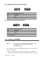
2.10 Installing SODIMMs.............. ............. 14
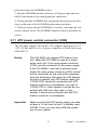
2.11 ATX power control connector (CN5) ............................. 15
2.12 Printer port connector (CN6)........................................... 16
2.13 CompactFlash Card Socket ............................................. 16
2.13.1 CompactFlash(CN21) ................................................... 16
2.14 Floppy drive connector (CN4) ........................................ 16
2.14.1 Connecting the floppy drive ......................................... 16
2.15 IDE connector(CN3,CN7)............................................... 17
2.15.1 Connecting the hard drive............................................. 17
2.16 VGA/LVDS interface connections.................................. 18
2.16.1 CRT display connector (CN11) ................................... 18
2.16.2 LVDS LCD panel connector(CN15) ............................ 18
2.16.3 LCD inverter connector(CN20) .................................... 18
2.16.4 DVI connector (CN16) ................................................. 18
2.17 USB connectors (CN9,CN10)......................................... 18
2.18 Ethernet configuration..................................................... 19
2.18.1 LAN connector (CN12) ................................................ 19
2.18.2 Network boot ................................................................ 19

PCI-6886 User’s Manual viii
2.19 Front Panel Connector (CN1) ......................................... 19
2.19.1 Reset (Pin7&Pin8) ....................................................... 19
2.19.2 HDD LED (Pin1&Pin2)................................................ 19
2.19.3 Power LED (Pin 3 & Pin 4) .......................................... 20
2.19.4 Suspend LED(Pin 5 & Pin 6)........................................ 20
2.19.5 Power Button (Pin 9 & Pin10)...................................... 20
2.20 COM port connector (CN8,CN13,CN14) ....................... 20
2.21 MINI PS/2, KB/Mouse connector (CN19)...................... 20
2.22 External KB Connector(CN18)....................................... 20
2.23 AC'97 interface Connector (CN17)................................. 21
2.24 DIO connector (CN2)..................................................... 21
2.25 SATA Connector (SA1, SA2)........................................ 21
Chapter 3 Software Configuration .................................24
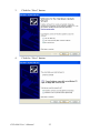
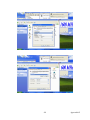
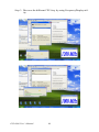
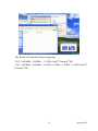
3.1 Introduction ..................................................................... 24
3.2 VGA display firmware configuration ............................. 24
Figure 3.1:VGA setup screen........................................ 25
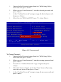
Chapter 4 Award BIOS Setup.........................................28
4.1 System test and initialization........................................... 28
4.1.1 System configuration verification................................. 28
4.2 Award BIOS setup .......................................................... 29
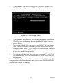
4.2.1 Entering setup .............................................................. 29
Figure 4.1:BIOS setup program initial screen .............. 29
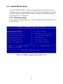
4.2.2 Standard CMOS Features setup.................................... 30
Figure 4.2:Standard CMOS Features setup .................. 30
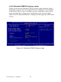
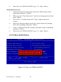
4.2.3 Advanced BIOS Features setup .................................... 31
Figure 4.3:Advanced BIOS Features setup................... 31
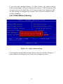
4.2.4 Advanced Chipset Features setup ................................. 32
Figure 4.4:Advanced Chipset Features setup ............... 32
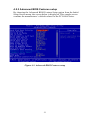
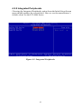
4.2.5 Integrated Peripherals ................................................... 33
Figure 4.5:Integrated Peripherals.................................. 33
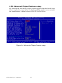
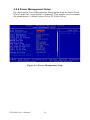
4.2.6 Power Management Setup ............................................ 34
Figure 4.6:Power Management Setup........................... 34
4.2.7 PnP/PCI Configurations................................................ 35
Figure 4.7:PnP/PCI Configurations .............................. 35
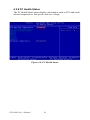
4.2.8 PC Health Status ........................................................... 36
Figure 4.8:PC Health Status.......................................... 36
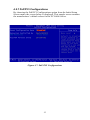
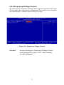
4.2.9 Frequency/Voltage Control........................................... 37
Figure 4.9:Frequency/Voltage Control ......................... 37
4.2.10 Load Optimized Defaults.............................................. 38
Figure 4.10:Load BIOS defaults screen........................ 38
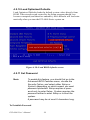
4.2.11 Set Password ................................................................. 38
Figure 4.11:Set password.............................................. 39
4.2.12 Save & Exit Setup......................................................... 40
Figure 4.12:Save to CMOS and EXIT.......................... 40

ix
4.2.13 Exit Without Saving...................................................... 41
Figure 4.13:Quit without saving ................................... 41
Chapter 5 PCI SVGA Setup ............................................44
5.1 Introduction ..................................................................... 44
5.1.1 Chipset .......................................................................... 44
5.1.2 Display memory............................................................ 44
5.1.3 Display types................................................................. 44
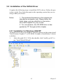
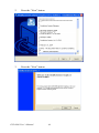
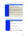
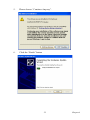
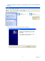
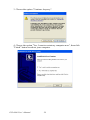
5.2 Installation of the SVGA Driver ..................................... 45
5.2.1 Installation for Windows 2000/XP ............................... 45
5.3 Further Information......................................................... 48
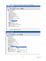
Chapter 6 PCI Bus Ethernet Interface...........................50
6.1 Introduction ..................................................................... 50
6.2 Installation of Ethernet driver ......................................... 50
6.2.1 Installation for Windows XP ........................................ 50
Chapter 7 Audio Setup.....................................................56
7.1 Introduction ..................................................................... 56
7.2 Driver installation............................................................ 56
7.2.1 Before you begin.......................................................... 56
7.2.2 Windows XP driver ..................................................... 56
Appendix A Programming GPIO & Watchdog Timer ....60
A.1 Supported GPIO Register................................................ 60
A.1.1 GPIO Registers ............................................................. 60
A.1.2 GPIO Example program-1........................................... 61
A.2 Watchdog programming................................................. 62
Appendix B Pin Assignments ............................................66
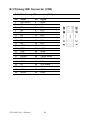
B.1 ATX power connector (CN5)......................................... 66
Table B.1:ATX power connector(CN5) ....................... 66
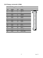
B.2 Floppy .................................................. connector (CN4)67
Table B.2:Floppy Connector (CN4) ............................. 67
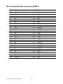
B.3 Primary IDE Connector (CN3) ....................................... 68
Table B.3:Primary IDE connector (CN3)..................... 68
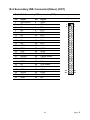
B.4 Secondary IDE Connector(Slave) (CN7)........................ 69
Table B.4:Secondary IDE connector (CN7)................. 69
B.5 CompactFlash connector(CN21)..................................... 70
Table B.5:CompactFlash Connector (CN21)................ 70
B.6 LAN,RJ45 connector(CN12) .......................................... 71
Table B.6:LAN,RJ45 connector(CN12) ....................... 71
B.7 USB1, 2 connector(CN10) .............................................. 71
Table B.7:USB 1, 2 connector(CN10).......................... 71
B.8 USB 3, 4 connector(CN9) ............................................... 72
Table B.8:USB 3, 4 connector(CN9)............................ 72
B.9 LCD INV power connector(CN20)................................. 72

PCI-6886 User’s Manual x
Table B.9:LCD INV power connector (CN20) ............ 72
B.10 DIO connector(CN2)....................................................... 73
Table B.10:DIO connector(CN2) ................................. 73
B.11 LVDS connector(CN15) ................................................. 74
Table B.11:LVDS connector (CN15) ........................... 74
B.12 LPT connector(CN6)....................................................... 75
Table B.12:LPT connector(CN6) ................................. 75
B.13 COM 1, 2 Connector (CN13, CN14) .............................. 76
Table B.13:COM connector (CN 13, CN14)................ 76
B.14 COM 3, 4 Connector (CN8)............................................ 77
Table B.14:COM3,4 Connector(CN8).......................... 77
B.15 Audio I/F connector(CN17) ............................................ 77
Table B.15:Audio I/F connector(CN17)....................... 77
B.16 D-SUB VGA connector(CN11) ...................................... 78
Table B.16:D-SUB VGA connector(CN11)................. 78
B.17 MINI PS/2_KB/Mouse connector(CN19)....................... 78
Table B.17:MINI Keyboard connector(CN19)............. 78
B.18 EXT_KB connector(CN18)............................................. 79
Table B.18:EXT_KB/Mouse connector(CN18) ........... 79
B.19 HDD LED/Reset/Power Button(CN1)............................ 79
Table B.19:HDD LED/Reset/Power Button(CN1)....... 79
B.20 DVI connector (CN16).................................................... 80
Table B.20:DVI connector(CN16) ............................... 80
B.21 CPU FAN connector (FAN1).......................................... 80
Table B.21:CPU FAN connector (FAN1) .................... 80
B.22 Serial ATA (SA1,SA2) ................................................... 81
Table B.22:Serial ATA (SA1, SA2) ............................. 81
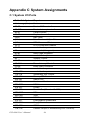
Appendix C System Assignments ......................................84
C.1 System I/O Ports.............................................................. 84
Table C.1:System I/O ports .......................................... 84
C.2 1st MB memory map....................................................... 85
Table C.2:1st MB memory map ................................... 85
C.3 DMA channel assignments.............................................. 85
Table C.3:DMA channel assignments .......................... 85
C.4 Interrupt assignments ...................................................... 86
Table C.4:Interrupt assignments ................................... 86
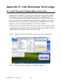
Appendix D Intel Speedstep Technology...........................88
D.1 Intel® Pentium® M SpeedStep instruction..................... 88

1 Chapter 1 General Information
1
General Information
This chapter gives background
information on the PCI-6886.
Sections include:
• Introduction
• Features
• Specifications
• Board layout and dimensions
CHAPTER

PCI-6886 User’s Manual 2
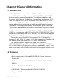
Chapter 1 General Information
1.1 Introduction
The PCI-6886 series is a half-sized PCI bus CPU card designed with
powerful Intel Celeron M processor, with Intel 852GM and 6300ESB
chipset, which supports enhanced Intel "SpeedStep" technology and
Dynamic Video Memory Technology. For maximum performance, PCI-
6886 also supports two 200PIN SODIMM socket that Non-ECC DDR
memory up to 2GB. These chipsets are specifically for embedded com-
puting and provide an optimized on-board integrated graphics solution.
"SpeedStep" technology intelligently focuses system power where the
CPU needs it and automatically regulates power usage to preserve battery
life.
Other on-board features include 2 EIDEs, 2 SATAs, 1 FDD, 1 LPT, 4
USB2.0s, 4 serial ports(3 x RS-232 and 1 x RS-232/422/485), PS/2 Key-
Board/mouse, watchdog, and a DIO interface. The SSD solution supports
Type I/II CompactFlash cards.
This product uses a Intel 852GM supports VGA/LVDS interface, 2
channel (36-bit) LVDS LCD panel . PCI-6886 supports AC97 audio with
the addition of the optional PCM-231A-00A1 audio module.
The Ethernet interface supports 10/100M Base-T by Intel
82551ER(82551QM optional), and 1000M Base-T by Intel 82540EM
(PCI-6886FG-M0A1).Its dimension is follow standard PCI slot PC, this
make it can match with all half-sized chasis and can operate in high vibra-
tion environment.
1.2 Features
• Intel new generation Celeron M 600MHz 0L2 cache Processor
Embedded
• Fanless operation at 0~60°C (PCI-6886F-M0A1 & PCI-6886FG-
M0A1)
• On board PCI VGA/LVDS/DVI display
• 1000BASE-T Ethernet on board(PCI-6886FG-M0A1)
• Supports 2 SATA

3 Chapter 1 General Information
• Supports 4 x USB2.0 port
• Supports 2 Channel 36bits LVDS for LCD
• Supports 400MHz Front Side Bus
• Supports 200-MHz, and 266-MHz DDR SDRAM
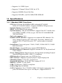
1.3 Specifications
1.3.1 Standard SBC Functions
• CPU:Intel Celeron M 600MHz(0 KB) onboard:(PCI-6886F-
M0A1,PCI-6886FG-M0A1). Supports 400MHz FSB processors
• System chipsets: Intel 852GM + 6300ESB
• BIOS: Award 4Mbit Flash memory
• System memory: 200 pin SODIMMx2, support Non-ECC double data
rate (DDR) 128MB to 2GB, accepts 128/256/512/1000MB DDR
200/266 DRAM
• 2nd cache memory: N/A
• Enhanced IDE Interface: Supports two enhanced IDE channels. Pri-
mary channel supports ATA-100 mode; Secondary channel only
supports ATA-33 and PIO mode. CFC card occupies secondary
master
• Serial Ports: Four serial ports: COM1, COM3, COM4: RS232, COM2:
RS232/422/485
• Parallel Ports: one parallel port, support SPP/EPP/ECP
• Keyboard/Mouse Connector:Supports standard PC/AT Keyboard and
a PS/2 Mouse
• Power Management: Supports Power Saving Mode including Normal/
Standard/Suspend modes. APM 1.2 compliant.
• FDD interface: Support up to two FDD devices
• DIO interface: Supports 8 general purpose input/output ports
• Watchdog Timer: 0~255 Sec, System reset
• Expansion Interface: 32-bit PCI Slot, support PCI 2.2
• Battery: Lithium 3V/195 mAH
• USB: 4 USB ports, USB 2.0 compliant
• SATA Chip: Intel 6300ESB
• SATA Connector: Two COMAX C504C (180 angle) connectors, sup-
ports data transfer rates up to 150 Mbyte/s, support RAID 0.1

PCI-6886 User’s Manual 4
1.3.2 Display Interface
• Chipset: Intel 852GM
• Memory size: Optimized Shared Memory Architecture,supports up to
64 MB frame buffer using system memory
• Display modes:
CRT Modes: up to 1600 x 1200 @32bpp (85Hz);
LCD Modes: up to UXGA panel resolutipn with frequency
range from 25-MHz to 112-MHz
• LCD Interface: 2 Channel LVDS (up to 36-bit)
• LVD S: Hirose connector support dual channel LVDS panel
1.3.3 DVI
• Chipset: Chrontel CH7009
• Drives a DVI display at a pixel rate of up to 165MHz, supporting
UXGA resolution displays
• DVI hot plug detection
• Compliant with DVI Specification 1.0
1.3.4 Solid State Disk
• Supports CompactFlash Type I/II disks
1.3.5 PCI bus Ethernet interface
• Chipset: Intel 82540EM(Gigabit), Intel 82551ER/82551QM(optional)
• Connection: on-board RJ-45
• Interface: IEEE 802.3 z/ab(1000BASE-T) or IEEE 802.3u(100BASE-
T) protocol compatible
•
BootROM:
build-in-system(Supported by 82540EM and
82551QM(optional))
1.3.6 Mechanical and Environmental
• Dimensions (L x W): 185 x 122 mm(7.3” x 4.8”)
• Power supply voltage: +5 V, +5V STB, +12V
• Power requirements:
Max:(Run Kpower under Win2000+SP4)
2.42A@5V,0.32A@12V,(w/CeleronM 600M0L2+512M)
Typical:(Run Kpower under Win2000+SP4)
1.91A@5V,0.31A@12V,(w/CeleronM 600M0L2+512M)
• Operating temperature: 0 ~ 60°C (32 ~ 140°F),operation
• Operating humidity: 0% ~ 90% Relative Humidity, Non condensing

5 Chapter 1 General Information
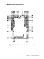
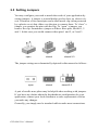
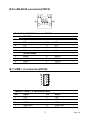
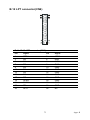
1.4 Board layout: dimensions
Figure 1.1: Board layout: dimensions (component side)

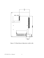
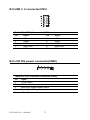
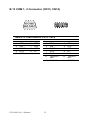
PCI-6886 User’s Manual 6
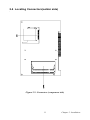
Figure 1.2: Board layout: dimensions (solder side)

7 Chapter 2 Installation
2
Installation
This chapter explains the setup procedures
of PCI-6886 hardware, including instruc-
tions on setting jumpers and connecting
peripherals, switches and indicators. Be
sure to read all safety precautions before
you begin the installation procedure.
CHAPTER

PCI-6886 User’s Manual 8
Chapter 2 Installation
2.1 Jumpers
The PCI-6886 has a number of jumpers that allow you to configure your
system to suit your application. The table below lists the functions of the
various jumpers.
Table 2.1: Jumpers
Label Function
JP1 COM2 RS232/422/485 Selection
JP2 CMOS Clear
JP3 LVDS Panel Power Selection
JP4 PCI Card Power Selection

9 Chapter 2 Installation
2.2 Connectors
On-board connectors link the PCI-6886 to external devices such as hard
disk drives, a keyboard, or floppy drives. The table below lists the func-
tion of each of the board’s connectors.
Table 2.2: Connectors
Label Function
CN1 Front Pannel Connector
CN2 Digital I/O Connector
CN3 Primary IDE Connector
CN4 Floppy Connector
CN5 ATX power Connector
CN6 Printer port Connector
CN7 Secondary IDE Connector
CN8 COM port 3, 4
CN9 USB port 3, 4
CN10 USB port 1, 2
CN11 D-SUB VGA Connector
CN12 LAN RJ45 Connector
CN13 COM port1
CN14 COM port 2
CN15 LVDS Connector
CN16 DVI Connector
CN17 AC'97 interface Connector
CN18 External KeyBoard Connector
CN19 MINI PS/2_KB/Mouse Connector
CN20 LCD inverter power connector
CN21 CompactFlash Socket
SA1 SATA Connector
SA2 SATA Connector
FAN1 CPU FAN Connector

PCI-6886 User’s Manual 10
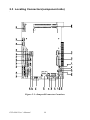
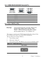
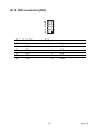
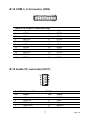
2.3 Locating Connectors(component side)
Figure 2.1: Jumper&Connector Locations
Page is loading ...
Page is loading ...
Page is loading ...
Page is loading ...
Page is loading ...
Page is loading ...
Page is loading ...
Page is loading ...
Page is loading ...
Page is loading ...
Page is loading ...
Page is loading ...
Page is loading ...
Page is loading ...
Page is loading ...
Page is loading ...
Page is loading ...
Page is loading ...
Page is loading ...
Page is loading ...
Page is loading ...
Page is loading ...
Page is loading ...
Page is loading ...
Page is loading ...
Page is loading ...
Page is loading ...
Page is loading ...
Page is loading ...
Page is loading ...
Page is loading ...
Page is loading ...
Page is loading ...
Page is loading ...
Page is loading ...
Page is loading ...
Page is loading ...
Page is loading ...
Page is loading ...
Page is loading ...
Page is loading ...
Page is loading ...
Page is loading ...
Page is loading ...
Page is loading ...
Page is loading ...
Page is loading ...
Page is loading ...
Page is loading ...
Page is loading ...
Page is loading ...
Page is loading ...
Page is loading ...
Page is loading ...
Page is loading ...
Page is loading ...
Page is loading ...
Page is loading ...
Page is loading ...
Page is loading ...
Page is loading ...
Page is loading ...
Page is loading ...
Page is loading ...
Page is loading ...
Page is loading ...
Page is loading ...
Page is loading ...
Page is loading ...
Page is loading ...
Page is loading ...
Page is loading ...
Page is loading ...
Page is loading ...
Page is loading ...
Page is loading ...
Page is loading ...
Page is loading ...
Page is loading ...
Page is loading ...
Page is loading ...
Page is loading ...
-
 1
1
-
 2
2
-
 3
3
-
 4
4
-
 5
5
-
 6
6
-
 7
7
-
 8
8
-
 9
9
-
 10
10
-
 11
11
-
 12
12
-
 13
13
-
 14
14
-
 15
15
-
 16
16
-
 17
17
-
 18
18
-
 19
19
-
 20
20
-
 21
21
-
 22
22
-
 23
23
-
 24
24
-
 25
25
-
 26
26
-
 27
27
-
 28
28
-
 29
29
-
 30
30
-
 31
31
-
 32
32
-
 33
33
-
 34
34
-
 35
35
-
 36
36
-
 37
37
-
 38
38
-
 39
39
-
 40
40
-
 41
41
-
 42
42
-
 43
43
-
 44
44
-
 45
45
-
 46
46
-
 47
47
-
 48
48
-
 49
49
-
 50
50
-
 51
51
-
 52
52
-
 53
53
-
 54
54
-
 55
55
-
 56
56
-
 57
57
-
 58
58
-
 59
59
-
 60
60
-
 61
61
-
 62
62
-
 63
63
-
 64
64
-
 65
65
-
 66
66
-
 67
67
-
 68
68
-
 69
69
-
 70
70
-
 71
71
-
 72
72
-
 73
73
-
 74
74
-
 75
75
-
 76
76
-
 77
77
-
 78
78
-
 79
79
-
 80
80
-
 81
81
-
 82
82
-
 83
83
-
 84
84
-
 85
85
-
 86
86
-
 87
87
-
 88
88
-
 89
89
-
 90
90
-
 91
91
-
 92
92
-
 93
93
-
 94
94
-
 95
95
-
 96
96
-
 97
97
-
 98
98
-
 99
99
-
 100
100
-
 101
101
-
 102
102


Intel PCI-6886 User manual
- Type
- User manual
- This manual is also suitable for
Ask a question and I''ll find the answer in the document
Finding information in a document is now easier with AI
Related papers
-
Intel MB875 User manual
-
Advantech PCM-9387 User manual
-
-
-
-
-
-
Intel PCM-9452 User manual
-
-
Other documents
-
Sharkoon 4044951006403 Datasheet
-
-
PEAK 259220FBPK Datasheet
-
protech PCI-531LF Operating instructions
-
-
-
 JS Automation JD50SHB120 User manual
-
-
-
