Dell PowerEdge 2650 User manual

Category
Server barebones
Type
User manual

This manual is also suitable for

Dell™PowerEdge™2650SystemsServiceManual
System Overview
Basic Troubleshooting
Indicators, Codes, and Messages
Removing and Replacing Parts
Jumpers and Connectors
Using the System Setup Program
Notes, Notices, and Cautions
Information in this document is subject to change without notice.
©2002DellComputerCorporation.Allrightsreserved.
Reproduction in any manner whatsoever without the written permission of Dell Computer Corporation is strictly forbidden.
Trademarks used in this text: Dell, the DELL logo, PowerEdge, and Dell OpenManage are trademarks of Dell Computer Corporation; Intel is a registered trademark and Xeon is a
trademark of Intel Corporation; Microsoft, MS-DOS, Windows NT, and Windows are registered trademarks of Microsoft Corporation.
Other trademarks and trade names may be used in this document to refer to either the entities claiming the marks and names or their products. Dell Computer Corporation
disclaims any proprietary interest in trademarks and trade names other than its own.
Initial release: 24 Apr 2002
NOTE: A NOTE indicates important information that helps you make better use of your computer.
NOTICE: A NOTICE indicates either potential damage to hardware or loss of data and tells you how to avoid the problem.
CAUTION: A CAUTION indicates a potential for property damage, personal injury, or death.
Back to Contents Page
Basic Troubleshooting
Dell™PowerEdge™2650SystemsServiceManual
Initial User Contact
External Visual Inspection
Observing the Boot Routine
Internal Visual Inspection
Running the System Diagnostics
Obtaining Technical Assistance
The basic troubleshooting procedures can help you diagnose a system problem. These procedures can often reveal the source of a problem or indicate the
correct starting point for servicing the system. See your Installation and Troubleshooting Guide for more detailed instructions for troubleshooting your system.
A brief explanation of how to load and start the system diagnostics can be found in "Running the System Diagnostics."
Perform the following procedures in the order presented.
Initial User Contact
When you first contact a user who has a problem, ask the user to describe the problem and the conditions under which it occurs. After the user describes the
problem, perform the following steps:
1. Ask the user to back up any data on the hard drive if the system's condition permits. See the documentation provided with the operating system or
applications software for information about backing up data.
2. Ask the user to try to duplicate the problem by repeating the operations he or she was performing at the time the problem occurred.
Can the user duplicate the problem?
Yes. Proceed to step 3.
No. Proceed to the next section, "External Visual Inspection."
3. Observe the user to determine if he or she is making an error, such as typing an incorrect key combination or entering a command incorrectly.
Is the problem a result of user error?
Yes. Instruct the user in the proper procedure or direct the user to the appropriate user documentation for the correct procedure.
No. Proceed to "External Visual Inspection."
External Visual Inspection
Improperly set switches and controls and loose or improperly connected cables are the most likely source of problems for the system, monitor, or other
peripherals (such as a keyboard, mouse, or other external equipment). A quick check of all the switches, controls, and cable connections can easily solve these
problems.
The external visual inspection consists of a quick inspection of the exterior of the system, the monitor, (if attached), the keyboard (if attached), any
peripherals, and cables. While performing the visual inspection, make any necessary corrections.
To perform the external visual inspection, perform the following steps:
1. Inspect the status indicators that can signify component malfunction.
2. Turn off the system, the monitor (if attached), and all peripherals.
3. Verify that all power cables are properly connected to the system, the monitor and peripherals, and their power sources.
4. Inspect connections to any attached devices including network cables, keyboard, monitor, mouse (if used), or keyboard/video/mouse (KVM) switch (if
used), as well as any devices attached to the serial port.
5. Inspect all external monitor controls for any obvious damage or improper settings (if used). For proper settings of the video monitor controls, see the
documentation for the monitor.
6. Inspect the keyboard (if used) to ensure that no keys are sticking. If keys are sticking, it may be necessary to replace the keyboard.
7. Inspect the exterior of the system, including all controls and indicators, and all user- accessible data storage devices for any signs of physical damage.
Does the inspection reveal any problems?
Yes. Proceed to the appropriate procedure in "Removing and Replacing Parts."
No. Proceed to "Observing the Boot Routine."
Observing the Boot Routine
After you have performed an external visual inspection, boot the system and, while the boot routine is running, observe the system for any indications of
problems.
To observe problem indications during the boot routine, perform the following steps:
1. If the system is off, turn on all peripherals and the system.
During the POST, the following message appears:
<F10> = Utility Mode
2. Press <F10> to access the utility mode.
The utility partition provides a text-based interface from which you can run the partition's utilities. To select a menu option, you can either use the arrow
keys to highlight the option and press <Enter>, or type the number of the menu option. To exit the utility partition, press <Esc> from the Main Menu.
Exiting the utility from the setup mode causes the system to reboot to the standard operating-system boot partition.
3. Check the power-supply indicators.
Is the red fault indicator lit?
Yes. Troubleshoot the system power supply (see your Installation and Troubleshooting Guide).
No. Proceed to step 4.
4. Watch the <Num Lock>, <Caps Lock>, and <Scroll Lock> indicators on the upper-right corner of the keyboard. After all three indicators flash
momentarily, and following a long pause (approximately 30 seconds), the <Num Lock> indicator should light up and remain on (unless the Num Lock
option is set to off in the System Setup Program).
Do these indicators flash on and off within approximately 10 seconds after the boot routine starts?
Yes. Proceed to step 5.
No. Replace the keyboard with a known working keyboard. If the problem persist, troubleshoot the system power supply. If the troubleshooting
procedure indicates that the system power supply is operational, troubleshoot the memory.
5. During the boot routine, observe the system for any of the following indications:
l Beep codes A beep code is a series of beeps that indicates an error condition. See "System Beep Codes."
l System error messages These messages can indicate problems or provide status information. If a system error message appears, see "System
Messages."
l Diskette-drive and hard drive access indicators These indicators light up in response to data being transferred to or from the drives. If either if
these indicators fails to light up during the boot routine, troubleshoot the diskette drive or hard drive subsystem, as appropriate.
6. From the utility partition's main menu, select the Run System Diagnostics option from Run System Utilities and observe the monitor screen for the
Diagnostics menu.
Does the Diagnostics menu appear?
Yes. See "Running the System Diagnostics."
No. Proceed to step 7.
7. Insert a copy of the diagnostics diskette into the diskette drive, and reboot the system.
Does the Diagnostics menu appear?
Yes. See "Running the System Diagnostics."
No. Proceed to "Internal Visual Inspection."
Internal Visual Inspection
A simple visual inspection of a system's interior hardware can often lead to the source of a problem, such as a loose expansion card, cable connector, or
mounting screw. When you perform the visual inspection, see "Jumpers and Connectors" to locate components referenced in the inspection procedure.
NOTE: Most of the steps in this procedure require observation of system functions and indications, some of which can occur simultaneously. It may be
necessary to reboot the system several times to complete all of these steps.
NOTE: You can run the system diagnostics from the utility partition by pressing <F10> during startup (this is the suggested method in most situations)
or from a set of diskettes created from the Dell OpenManage Server Assistant CD.
NOTICE: Before you proceed with the internal visual inspection described in this section, ensure that the user has saved all open files and exited all
open application programs, if possible.
CAUTION: Before you perform this procedure, read the safety instructions in your System Information document.
CAUTION: See "Protecting Against Electrostatic Discharge" in the safety instructions in your System Information document.
1. Remove the bezel (see "Removing the Bezel").
2. Turn off the system, including any attached peripherals, and disconnect all the power cables from electrical outlets.
3. Remove the cover (see "Removing the Cover").
4. Verify that the memory modules, expansion cards, and microprocessors are fully seated in their sockets or connectors.
l To remove and reseat microprocessors, perform the steps described in "Microprocessors."
l To remove and reseat a memory module, perform the steps described in "Memory Modules."
l To remove and reseat an expansion card, perform the steps described in "Expansion Cards."
5. Verify that all jumpers are set correctly (see Figure5-2).
6. Check all cable connectors inside the system to verify that they are firmly attached to their appropriate connectors.
7. Replace the cover (see "Replacing the Cover").
8. Reconnect the system and any attached peripherals to their power sources, and turn them on.
Does the problem appear to be resolved?
Yes. No further steps are necessary
No. Proceed to "Obtaining Technical Assistance."
Running the System Diagnostics
You can run system diagnostics from either the utility partition on your hard drive or from a set of diskettes that you create from the Dell OpenManage Server
AssistantCD.
To run the diagnostics from the utility partition, perform the following steps:
1. Start the utility partition by pressing <F10> during POST.
2. From the utility partition's main menu, select the Run System Diagnostics option from Run System Utilities.
See "Using the Dell OpenManage Server Assistant CD" in the User's Guide for additional information about the utility partition.
To run the system diagnostics from the diskettes, perform the following steps:
1. Create a set of diagnostics diskettes using the Dell OpenManage Server Assistant CD.
See "Using the Dell OpenManage Server Assistant CD" in the User's Guide for information on creating diskettes.
2. Boot the system from the first diagnostics diskette.
If the system fails to boot, see "Obtaining Technical Assistance."
When you start the diagnostics, a message is displayed telling you that the diagnostics is loading. The Diagnostics menu appears. The menu allows you to
run all or specific diagnostic tests or to exit system diagnostics.
For a quick check of the system, select Test All Devices and then select Quick Tests. This option runs only the device tests that do not require user
interaction and that do not take a long time to run. Dell recommends that you choose this option first to increase the chance of tracing the source of the
problem quickly. To test a particular device, select Test One Device. For a complete check of the system, select Test All Devices and then select Extended
Tests.
To check a particular area of the system, choose Advanced Testing. When you select Advanced Testing, the main screen of the diagnostics appears. This
screen includes a listing of the various device groups in the system and the system's service tag.
To view data on test results, select Information and Results. Select Program Options to view the program options screen, which lets you set various test
parameters.
By selecting the Device Configuration option, you can see an overview of the devices in the system.
Selecting Exit to MS-DOS exits the diagnostics and returns you to the MS-DOS®operating system environment.
To select an option from the Diagnostics menu, highlight the option and press <Enter>, or press the key that corresponds to the highlighted letter in the
option you choose.
Obtaining Technical Assistance
If at any time you do not understand a procedure described in this guide or if your system does not perform as expected, there are a number of tools are
CAUTION: The microprocessor and heat-sink assembly can get extremely hot during system operations. Be sure that it has had sufficient time to
cool before touching it.
CAUTION: When handling the microprocessor and heat-sink assembly, take care to avoid sharp edges on the heat sink.
provided to assist you. For more information on these help tools, see "Getting Help" in your Installation and Troubleshooting Guide.
Back to Contents Page
Indicators, Codes, and Messages
Dell™PowerEdge™2650SystemsServiceManual
The system indicators and features are illustrated in this section. This section also describes each type of message, and lists the possible causes and actions
you can take to resolve any problems indicated by a message.
System-Status Indicators
The system's bezel has an indictor that can represent system status when the bezel is installed (see Figure3-1). The indicator signifies when the system is
operating properly or when the system needs attention. The back-panel indicator functions the same as the bezel indicator. The back-panel indicator
connector allows an indicator to be attached that will also function the same as the bezel indicator (see Figure3-3).
A caution code signifies a problem with microprocessors, power supply, system or power-supply fans, system temperature, hard drives, system memory,
expansion cards, or integrated SCSI controller.
Table3-1 lists the system's status indicator codes.
Figure 3-1. System-Status Indicators
System Identification Indicators
The identification buttons on the front and back panels can be used to identify a particular system within a rack. See Figure3-2 to locate the front-panel
system identification button. See Figure3-3 to locate the back-panel system identification button and indicator.
When either of the identification buttons is pushed, the identification indicator on the back blinks until one of the buttons is pushed again. If the bezel is
installed, the system status indicator will also blink. If an indicator is connected to the back-panel system status indicator connector, that indicator will also
blink.
Systems management software can also be used to cause the status and identification indicators to blink to identify a particular system. For more information,
see the systems management software documentation.
Front-Panel Indicators and Features
System-Status Indicators
System Identification Indicators
Front-Panel Indicators and Features
Back-Panel Indicators and Features
Power Indicator Codes
Hard-Drive Indicator Codes
NIC Indicator Codes
Cooling Fan Indicator Codes
LCD Status Messages
System Messages
System Beep Codes
Warning Messages
Diagnostics Messages
Alert Messages
Table 3-1. System-StatusIndicatorCodes
Bezel Indicators
Back-Panel Indicators
Indicator Code
Status
Caution
Off
Off
Off
No power is available to the system, or the system is not powered on.
On
Off
Blue
The system is operating normally.
Off
Blinking
Amber blinking
The system has detected an error and requires attention.
Blinking
Off
Blue blinking
The system is identifying itself (see "System Identification Indicators").
Additional indicators are located behind the bezel. The front-panel status LCD provides information using an alphanumeric character display (see "LCD Status
Messages"). See Figure3-2 for the front-panel indicators and features.
Figure3-2 shows the front-panel features of the system. Table3-2 describes the front-panel features.
Figure 3-2. Front-Panel Features
Back-Panel Indicators and Features
Figure3-3 shows the back-panel features of the system. Table3-3 describes the back-panel features.
Figure 3-3. Back-Panel Features
Table 3-2. Front-PanelFeatures
Component
Description
Power button
Turns system power off and on.
l If you turn off the system using the power button and the system is running an ACPI-compliant operating system (such as
Microsoft®Windows®2000), the system can perform an orderly shutdown before power is turned off.
l If the system is not running an ACPI-compliant operating system, power is turned off immediately after the power button is
pressed.
The button is enabled in the System Setup program. When disabled, the button can only turn system power on. For more information,
see your User's Guide and the operating system's documentation.
Power indicator
Provides information on power status (see "Power Indicator Codes").
CD and diskette
drive indicators
Indicates read or write access to the respective drive.
hard-drive
indicators
Provide information on the status of the respective hard drive (see "Hard-Drive Indicator Codes").
NIC indicators
Indicate whether the NIC has a valid link to the network (see "NIC Indicator Codes").
Status LCD
Can signify when the system is operating correctly or when the system needs attention (see "LCD Status Messages").
System
identification button
Can be used to identify a particular system (see "System Identification Indicators").
NMI button
Can be used to troubleshoot software and device driver errors when using certain operating systems. This button is often referred to
as a "force dump switch" and can be pressed using the end of a paper clip. When the option is enabled in the System Setup program
and the button is pressed, an NMI alerts the system.
Use this button only if directed to do so by qualified support personnel or by the operating system's documentation. For more
information, see your User's Guide and the operating system's documentation.
Bezel connector
Transmits logic signals for the system-status indicator on the bezel (see "System-Status Indicators").
I/O ports and
connectors
Attach peripheral devices to the system. For more information, see "I/O Ports and Connectors" in your User's Guide.
Power Indicator Codes
The system has indicators on the front panel and the power supplies that signify system power status.
Power-Button Indicator Codes
The power button controls the power input to the system's power supplies. The power button indicator can provide information on power status (see Figure3-
2).
Table3-4 lists the power button indicator codes.
Power-Supply Indicator Codes
Each hot-pluggable AC or DC power supply has indicators that can provide information on power status, fault, and the presence of power (see Figure3-4).
Table3-5 lists the power-supply indicator codes.
Figure 3-4. Power-Supply Indicators
Table 3-3. Back-PanelFeatures
Component
Description
Power supply indicators
Provides information on power status (see "Power Indicator Codes").
NIC indicators
Provides information on NIC status (see "NIC Indicator Codes").
System status indicator connector
Connects to an indicator that can signify when the system is operating correctly or when the system needs attention
(see "System-Status Indicators").
System identification indicator
Signifies when the system is operating correctly or when the system needs attention, and can identify a particular
system (see "System Identification Indicators").
System identification button
Can be used to identify a particular system (see "System Identification Indicators").
Expansion slots
The expansion cards are installed on the system's riser board (see Figure5-4 to identify the expansion slots).
I/O ports and connectors
Attach peripheral devices to the system. For more information, see "I/O Ports and Connectors" in your User's Guide.
Embedded remote access Ethernet
connector
Used for remote system administration. For more information, see your systems management documentation.
Power connectors and grounding
post
Connects the system's power supplies to a power source (see "Power Supplies").
Table 3-4. Power-ButtonIndicatorCodes
Indicator
Indicator Code
On
Indicates that power is supplied to the system, and the system is operational.
Off
Indicates that no power is supplied to the system.
Blinking
Indicates that power is supplied to the system, but the system is in a standby state. For more information on standby states, see your operating
system documentation.
Hard-Drive Indicator Codes
Each hard-drive carrier has two indicators: a busy indicator and a status indicator (see Figure3-5). The indicators provide information on the status of the
respective hard drive. Table3-6 lists the drive indicator codes.
Figure 3-5. Hard-Drive Indicators
Table3-6 lists the drive indicator codes. Different codes display as drive events occur in the system. For example, in the event of a hard-drive failure, the "drive
failed" code appears. After the drive is selected for removal, the "preparing for removal" code appears. After the replacement drive is installed, the "preparing
for operation, drive online" code appears.
Table 3-5. Power-SupplyIndicatorCodes
Indicator
Indicator Code
Power-on
Green indicates that the power supply is operational.
Fault
Red indicates a problem with the power supply (fan failure, voltage error, etc.).
Power present
Green indicates that power is present at the power supply and that the system is connected to a power source.
Table 3-6. Hard-DriveIndicatorCodes
Indicator
Indicator Code
Drive bay empty, ready for insertion or removal
Off
Drive being prepared for operation, drive online
Steady green
Drive being identified
Blinks green four times per second
Drive being prepared for removal
Blinks green twice per second at equal intervals
Drive rebuilding
Blinks green twice per second at unequal intervals
Drive failed
Blinks amber four times per second
NIC Indicator Codes
Each NIC on the back panel has an indicator that provides information on network activity and link status (see Figure3-6). Table3-7 lists the NIC indicator
codes on the back panel.
The front panel has a link indicator for each NIC (see Figure3-2). Each indicator signifies whether the corresponding NIC is connected to a valid link partner on
the network.
Figure 3-6. NIC Indicators
Cooling Fan Indicator Codes
Each individual fan has a status indicator on the system board adjacent to the respective fan's connector (see Figure3-7). To locate the fan connectors on the
system board, see Figure5-3. Table3-8 lists the fan indicator codes.
Figure 3-7. Cooling Fan Indicators
LCD Status Messages
The system's bezel indictor can signify when the system is operating correctly or when the system needs attention (see Figure3-1). When the bezel indicator
signifies an error condition, remove the bezel to see further information provided by the status LCD.
The LCD can display two lines of alphanumeric characters. The display codes are presented in two color combinations:
l White characters on a blue background Information only; no action is required.
l Amber characters on a black background The system needs attention.
Table3-9 lists the LCD status messages that can occur and the probable cause for each message. The LCD messages refer to events recorded in the SEL. For
information on the SEL and configuring system management settings, see the systems management software documentation.
Predicted failure for the drive
Blinks green, then amber, and then off, repeating this sequence every two seconds
NOTE: The "drive busy" indicator signifies whether the hard drive is active on the SCSI bus. This indicator is controlled by the hard drive.
Table 3-7.NICIndicatorCodes
Indicator
Indicator Code
Link and activity indicators are off
The NIC is not connected to the network.
Link indicator is green
The NIC is connected to a valid link partner on the network.
Activity indicator is amber blinking
Network data is being sent or received.
Table 3-8.CoolingFanIndicatorCodes
Indicator
Indicator Code
Off
The fan is not required.
Green
The fan is functioning properly.
Amber blinking
The fan is malfunctioning.
Table 3-9.LCDStatusMessages
Line 1
Message
Line 2
Message
Causes
Corrective Actions
SYSTEM
ID
SYSTEM NAME
SYSTEM ID is a unique name, five
characters or less, defined by the user.
SYSTEM NAME is a unique name, 16
characters or less, defined by the user.
The system ID and name display under
the following conditions:
l The system is powered on.
l The power is off and active POST
errors are displayed.
This message is for information only.
You can change the system ID and name in the System Setup program (see "Using
the System Setup Program").
E0000
OVRFLW CHECK
LOG
LCD overflow message.
A maximum of three error messages can
display sequentially on the LCD. The
fourth message displays as the standard
overflow message.
Check the SEL for details on the events.
E0119
TEMP AMBIENT
Ambient system temperature is out of
acceptable range.
Ensure that the system cooling fans are properly installed. If the problem persists,
replace the faulty fan(s) (see "System Fans").
E0119
TEMP BP
Backplane board is out of acceptable
temperature range.
Ensure that the system cooling fans are properly installed. If the problem persists,
replace the faulty fan(s) (see "System Fans"). If the problem persists, replace the
backplane board (see "SCSI Backplane Board").
E0119
TEMP CPU n
Specified microprocessor is out of
acceptable temperature range.
Ensure that the system cooling fans are properly installed. If the problem persists,
replace the faulty fan(s) (see "System Fans"). If the problem persists, ensure that the
specified microprocessor's heat sink is properly installed. If the problem persists,
replace the faulty microprocessor (see "Microprocessors").
E0119
TEMP SYSTEM
System board is out of acceptable
temperature range.
Ensure that the system cooling fans are properly installed. If the problem persists,
replace the faulty fan(s) (see "System Fans"). If the problem persists, replace the
system board (see "System Board").
E0212
VOLT 3.3
System power supply is out of acceptable
voltage range; faulty or improperly
installed power supply.
Ensure that the power supplies are properly installed. If the problem persists, replace
the faulty power supply(s) (see "Power Supplies").
E0212
VOLT 5
E0212
VOLT 12
E0212
VOLT BATT
Faulty battery; faulty system board.
Ensure that the system battery is properly installed. If the problem persists, replace
the battery (see "System Battery"). If the problem persists, replace the system board
(see "System Board").
E0212
VOLT BP 12
Backplane board is out of acceptable
voltage range.
Ensure that the power cables are securely connected to the backplane board (see
"SCSI Backplane Board"). Ensure that the power supplies are properly installed. If the
problem persists, replace the faulty power supply(s) (see "Power Supplies").
E0212
VOLT BP 3.3
E0212
VOLT BP 5
E0212
VOLT CPU VRM
Microprocessor VRM voltage is out of
acceptable range; faulty or improperly
installed microprocessor VRM; faulty
system board.
Ensure that supported VRMs of the same type are properly installed. If the problem
persists, replace the VRMs (see Figure4-29). If the problem persists, replace the
system board (see "System Board").
E0212
VOLT NIC
1.8V
Integrated NIC voltage is out of
acceptable range; faulty or improperly
installed power supply; faulty system
board.
Ensure that the power supplies are properly installed. If the problem persists, replace
the faulty power supply(s) (see "Power Supplies"). If the problem persists, replace
the system board (see "System Board").
E0212
VOLT NIC
2.5V
E0212
VOLT PLANAR
REG
System board is out of acceptable voltage
range; faulty or improperly installed
system board.
E0276
CPU VRM n
Specified microprocessor VRM is faulty,
unsupported, improperly installed, or
missing.
Ensure that supported VRMs of the same type are properly installed. If the problem
persists, replace the VRM (see Figure4-29).
E0276
MISMATCH VRM
n
E0280
MISSING VRM
n
E0319
PCI OVER
CURRENT
Faulty or improperly installed expansion
card.
Ensure that the expansion cards are properly installed. If the problem persists,
replace the faulty expansion card(s) (see "Expansion Cards").
E0412
RPM FAN n
Specified cooling fan is faulty, improperly
installed, or missing.
Ensure that the system cooling fans are properly installed. If the problem persists,
replace the faulty fan(s) (see "System Fans").
E0780
MISSING CPU
n
Microprocessor is not installed in the
specified socket.
A microprocessor must be installed in socket 1, and a VRM must be installed for each
installed microprocessor. Install a microprocessor in the specified socket or remove
the VRM for the specified microprocessor if that microprocessor is not installed (see
"Microprocessors"). To identify the microprocessors and VRMs, see Figure5-3.
E07F0
CPU IERR
Faulty or improperly installed
microprocessor.
Ensure that the microprocessors are properly installed. If the problem persists,
replace the faulty microprocessor(s) (see "Microprocessors").
E07F1
TEMP CPU n
HOT
Specified microprocessor is out of
acceptable temperature range and has
halted operation.
Ensure that the system cooling fans are properly installed. If the problem persists,
replace the faulty fan(s) (see "System Fans"). If the problem persists, ensure that the
microprocessor heat sinks are properly installed. If the problem persists, replace the
faulty microprocessor (see "Microprocessors").
E07F4
POST CACHE
Faulty or improperly installed
microprocessor.
Ensure that the microprocessors are properly installed. If the problem persists,
replace the faulty microprocessor(s) (see "Microprocessors").
E07F4
POST CPU REG
E07F4
POST CPU SMI
SMI handler failed to initialize; faulty
system board.
Replace the system board (see "System Board").
E07FA
TEMP CPU n
THERM
Specified microprocessor is out of
acceptable temperature range and is
operating at a reduced speed, or
frequency.
Ensure that the system cooling fans are properly installed. If the problem persists,
replace the faulty fan(s) (see "System Fans"). If the problem persists, ensure that the
microprocessor heat sinks are properly installed. If the problem persists, replace the
faulty microprocessor (see "Microprocessors").
E0876
POWER PS n
No power available from the specified
power supply; specified power supply is
improperly installed or faulty.
Ensure that the power supplies are properly installed. If the problem persists, replace
the faulty power supply(s) (see "Power Supplies").
E0880
INSUFFICIENT
PS
Insufficient power is being supplied to the
system; power supplies are improperly
installed, faulty, or missing.
E0CB2
MEM SPARE
BANK
Correctable errors threshold was met in a
memory bank: errors were remapped to
the spare bank.
Ensure that the memory modules are properly installed. If the problem persists,
replace the faulty memory module(s) (see "Memory Modules").
E0CF1
MBE DIMM
Bank n
Memory modules installed in the specified
bank are not the same type and size;
faulty memory module(s).
Ensure that all banks contain memory modules of the same type and size and that
they are properly installed. If the problem persists, replace the faulty memory module
(s) (see "Memory Modules").
E0CF1
POST MEM 64K
Parityfailureinthefirst64KBofmain
memory.
Ensure that the memory modules are properly installed. If the problem persists,
replace the faulty memory module(s) (see "Memory Modules").
E0CF1
POST NO
MEMORY
Main-memory refresh verification failure.
Ensure that all banks contain memory modules of the same type and size and that
they are properly installed. If the problem persists, replace the faulty memory module
(s) (see "Memory Modules").
E0CF5
LOG DISABLE
SBE
Multiple single-bit errors on a single
memory module.
Ensure that the memory modules are properly installed. If the problem persists,
replace the faulty memory module(s) (see "Memory Modules").
E0D76
DRIVE FAIL
Faulty or improperly installed hard drive or
RAID controller.
Ensure that the hard drives are properly installed. If the problem persists, replace the
faulty hard drive(s) (see "Hard Drives"). If the problem persists, replace the RAID
controller (see "Integrated RAID Controller" and "RAID Controller Card").
E0F04
POST CMOS
CMOS write/read failure; faulty system
board.
Replace the system board (see "System Board").
E0F04
POST CPU
SPEED
Microprocessor speed control sequence
failure.
Ensure that the microprocessors are properly installed. If the problem persists,
replace the faulty microprocessor(s) (see "Microprocessors").
E0F04
POST DMA
INIT
DMA initialization failure; DMA page
register write/read failure.
Ensure that the memory modules are properly installed. If the problem persists,
replace the faulty memory module(s) (see "Memory Modules").
E0F04
POST DMA REG
Faulty system board.
Replace the system board (see "System Board").
E0F04
POST KYB
CNTRL
Faulty keyboard controller; faulty system
board.
Replace the system board (see "System Board").
E0F04
POST MEM
RFSH
Main-memory refresh verification failure.
Ensure that the memory modules are properly installed. If the problem persists,
replace the faulty memory module(s) (see "Memory Modules").
E0F04
POST PIC REG
Master or slave PIC register test failure.
Replace the system board (see "System Board").
E0F04
POST SHADOW
BIOS-shadowing failure.
Ensure that the memory modules are properly installed. If the problem persists,
replace the faulty memory module(s) (see "Memory Modules").
E0F04
POST SHD
TEST
Shutdown test failure.
E0F04
POST SIO
Super I/O chip failure; faulty system
board.
Replace the system board (see "System Board").
E0F04
POST TIMER
Programmable interval timer test failure;
faulty system board.
Replace the system board (see "System Board").
E0F0B
POST ROM
CHKSUM
Faulty or improperly installed expansion
card.
Ensure that the expansion cards are properly installed. If the problem persists,
replace the faulty expansion card(s) (see "Expansion Cards").
E0F0C
VID MATCH
CPU n
Specified microprocessor is faulty,
unsupported, improperly installed, or
missing.
Ensure that the microprocessors are properly installed. If the problem persists,
replace the faulty microprocessor(s) (see "Microprocessors").
E10F3
LOG DISABLE
BIOS
BIOS disabled logging errors.
Check the SEL for details on the errors.
E13F2
IO CHANNEL
CHECK
Faulty or improperly installed expansion
card; faulty system board.
Ensure that the expansion cards are properly installed. If the problem persists,
replace the faulty expansion card(s) (see "Expansion Cards"). If the problem persists,
replace the system board (see "System Board").
E13F4
PCI PARITY
E13F5
PCI SYSTEM
E13F8
CPU BUS INIT
Faulty or improperly installed
microprocessor or system board.
Ensure that the microprocessors are properly installed. If the problem persists,
replace the faulty microprocessor(s) (see "Microprocessors"). If the problem persists,
replace the system board (see "System Board").
E13F8
CPU BUS
PARITY
Faulty system board.
Replace the system board (see "System Board").
E13F8
CPU MCKERR
Machine check error; faulty or improperly
installed microprocessor; faulty system
board.
Ensure that the microprocessors are properly installed. If the problem persists,
replace the faulty microprocessor(s) (see "Microprocessors"). If the problem persists,
replace the system board (see "System Board").
E13F8
HOST BUS
Faulty system board.
Replace the system board (see "System Board").
E13F8
HOST TO PCI
BUS
E13F8
MEM
CONTROLLER
Faulty or improperly installed memory
module; faulty system board.
Ensure that the memory modules are properly installed. If the problem persists,
replace the faulty memory module(s) (see "Memory Modules"). If the problem
persists, replace the system board (see "System Board").
E1580
POWER
CONTROL
Faulty system board.
Replace the system board (see "System Board").
E20F1
OS HANG
Operating system watchdog timer timed
out.
Restart your system. If the problem persists, see your operating system
documentation.
Solving Problems Described by LCD Status Messages
When a single message appears on the status LCD, locate the code in Table3-9 and perform the suggested corrective action. The code on the LCD can often
specify a very precise fault condition that is easily corrected. For example, if the code E0280MISSINGVRM2 appears, you know that a microprocessor is
installed in socket 2, but the VRM for that microprocessor is either improperly installed or missing.
In contrast, you might be able to determine the problem if multiple related errors occur. For example, if you receive a series of messages indicating multiple
voltage faults, you might determine that the problem is a failing power supply.
Removing LCD Status Messages
For faults associated with sensors, such as temperature, voltage, fans, and so on, the LCD message is automatically removed when that sensor returns to a
normal state. For example, if temperature for a component goes out of range, the LCD displays the fault; when the temperature returns to the acceptable
range, the message is removed from the LCD. For other faults, you must take action to remove the message from the display:
l Clear the SEL You can perform this task remotely, but you will lose the event history for the system.
l Chassis intrusion When you remove the cover, the system assumes that you are servicing the bad component; the LCD clears when you replace the
cover.
l Power cycle Turn off the system and disconnect it from the electrical outlet; wait approximately ten seconds, reconnect the power cable, and restart
the system.
Any of these actions will remove fault messages, and return the status indicators and LCD colors to the normal state. Messages will reappear under the
following conditions:
l The sensor returns to a normal state but fails again, resulting in a new SEL entry.
l The system is reset and new error events are detected.
l A failure is recorded from another source that maps to the same display entry.
System Messages
System messages appear on the console during POST to notify you of a possible problem with the system. If you are performing console redirection, system
messages will appear on the remote console. Table3-10 lists the system messages that can occur and the probable cause for each message.
EFFF0
RAC ERROR
Remote access controller firmware failure;
faulty system board.
Replace the expansion-card riser board (see "Expansion-Card Riser Board").
EFFF1
POST ERROR
BIOS error.
UpdatetheBIOSfirmware.DownloadthelatestfirmwarefromtheDell|Support
website at support.dell.com.
EFFF2
BP ERROR
Faulty or improperly installed backplane
board.
Ensure that the interface cables are securely connected to the SCSI backplane board.
If the problem persists, replace the backplane board (see "SCSI Backplane Board").
NOTE: If you receive a system message that is not listed in Table3-10, check the documentation for the application program that is running when the
message appears or the operating system's documentation for an explanation of the message and recommended action.
Table 3-10.SystemMessages
Message
Causes
Corrective Actions
Address mark not found
Faulty CD/diskette drive
subsystem or hard-drive
subsystem; faulty system board.
Replace the faulty drive(s) (see "CD and Diskettes Drives" and "Hard
Drives"). If the problem persists, replace the system board (see "System
Board").
Alert! Current configuration does not
support redundant memory. Redundant
memory is disabled.
Memory modules installed are not
the same type and size in all
banks; faulty memory module(s).
Ensure that all banks contain memory modules of the same type and
size and that they are properly installed. If the problem persists, replace
the faulty memory module(s) (see "Memory Modules").
Alert! Unsupported memory or incomplete
sets in the following bank(s): Bank n
Memory modules installed in the
specified bank are not the same
type and size; faulty memory
module(s).
Amount of available memory limited to 256
MB!
OS Install Mode is enabled in the
System Setup program.
Disable OS Install Mode in the System Setup program (see "Using the
System Setup Program").
Auxiliary device failure
Loose or improperly connected
mouse or keyboard cable; faulty
mouse or keyboard.
Check the mouse and keyboard cables and connectors. If the problem
persists, replace the mouse and keyboard. If the problem persists,
replace the system board (see "System Board").
BIOS Update Attempt Failed!
Remote BIOS update attempt
failed.
Retry the BIOS update. Download the latest firmware from the
Dell|Supportwebsiteatsupport.dell.com.
CD-ROM drive not found
Improperly connected or missing
CD drive.
Ensure that the CD drive is properly installed. If the problem persists,
replace the CD drive (see "CD and Diskettes Drives").
CPUs with different cache sizes detected
Microprocessors with different
cache sizes are installed.
Ensure that all microprocessors have the same cache size and that they
are properly installed (see "Microprocessors").
Decreasing available memory
Faulty or improperly installed
memory modules.
Ensure that the memory modules are properly installed. If the problem
persists, replace the faulty memory module(s) (see "Memory Modules").
Diskette drive n seek failure
Incorrect configuration settings in
the System Setup program.
Run the System Setup program to correct the settings (see "Using the
System Setup Program").
Faulty or improperly installed
diskette drive.
Ensure that the diskette drive is properly installed. If the problem
persists, replace the diskette drive (see "CD and Diskettes Drives").
Diskette read failure
Faulty or improperly inserted
diskette.
Replace the diskette.
Diskette subsystem reset failed
Faulty or improperly installed
diskette drive.
Ensure that the diskette drive is properly installed. If the problem
persists, replace the diskette drive (see "CD and Diskettes Drives").
ECC memory error
Faulty or improperly installed
memory modules.
Ensure that the memory modules are properly installed. If the problem
persists, replace the faulty memory module(s) (see "Memory Modules").
Error: Maximum PCI option ROM count
exceeded!
Too many expansion cards have
ROM enabled in the System Setup
program.
Disable ROM for some of the expansion cards (see "Using the System
Setup Program").
Gate A20 failure
Faulty keyboard controller; faulty
system board.
Replace the system board (see "System Board").
Hard disk controller failure
Incorrect configuration settings in
System Setup program;
improperly installed hard drive, or
loose interface or power cable;
faulty hard-drive controller
subsystem.
Run the System Setup program to correct the drive type (see "Using the
System Setup Program"). If the problem persists, ensure that the hard
drives are properly installed (see "Hard Drives"). If the problem persists,
replace the system board (see "System Board").
Hard disk read failure
I/O parity interrupt at address
Faulty or improperly installed
expansion card.
Ensure that the expansion cards are properly installed. If the problem
persists, replace the faulty expansion card(s) (see "Expansion Cards").
Invalid configuration information -
please run SETUP program
Incorrect configuration settings in
System Setup program;
NVRAM_CLR jumper is installed;
faulty system battery.
Check the System Setup configuration settings (see "Using the System
Setup Program"). Remove the NVRAM_CLR jumper (see Figure5-2 for
jumper location). If the problem persists, replace the system battery
(see "System Battery").
Invalid NVRAM configuration, resource re-
allocated
System configuration data has
been ignored.
Check the System Setup configuration settings (see "Using the System
Setup Program").
Invalid SCSI configuration
SCSI cable detected on connector SCSIB of
the SCSI backplane, daughter card not
present
A SCSI cable is connected to the
channel B connector on the SCSI
backplane board; SCSI backplane
daughter card is not installed.
If a cable is connected to the SCSIB backplane board connector, the
SCSI backplane daughter card must be installed. Ensure that the
backplane daughter card is properly installed (see "SCSI Backplane
Daughter Card").
Keyboard controller failure
Faulty keyboard controller; faulty
system board.
Replace the system board (see "System Board").
Keyboard clock line failure
Loose or improperly connected
keyboard cable; faulty keyboard;
faulty keyboard controller.
Check the keyboard cable and connector. If the problem persists, replace
the keyboard. If the problem persists, replace the system board (see
"System Board").
Keyboard data line failure
Keyboard failure
Keyboard stuck key failure
Memory address line failure at address,
read value expecting value
Faulty or improperly installed
memory modules.
Ensure that the memory modules are properly installed. If the problem
persists, replace the faulty memory module(s) (see "Memory Modules").
Memory double word logic failure at
address, read value expecting value
Memory high address line failure at start
address to end address
Memory high data line failure at start
address to end address
Memory odd/even logic failure at start
address to end address
Memory parity failure at start address to
end address
Memory parity error at address
Memory write/read failure at address,
read value expecting value
No boot device available
Faulty or missing CD/diskette
drive subsystem, hard drive, or
hard-drive subsystem.
Check the configuration settings in the System Setup program for
Integrated Devices (see "Using the System Setup Program"). If booting
from a SCSI controller, ensure that the controller is properly connected.
If the problem persists, replace the faulty drive(s) (see "CD and
Diskettes Drives" and "Hard Drives"). If the problem persists, replace the
system board (see "System Board").
No boot sector on hard- disk
No operating system on hard
drive.
Check the hard-drive configuration settings in the System Setup program
(see "Using the System Setup Program").
No PXE-capable device available
<F12> pressed during POST and
no PXE devices are detected.
Check the configuration settings in the System Setup program for the
NICs (see "Using the System Setup Program").
No timer tick interrupt
Faulty system board.
Replace the system board (see "System Board").
Not a boot diskette
No operating system on diskette.
Use a bootable diskette.
PCI BIOS failed to install
Loose cables to expansion card
(s); faulty or improperly installed
expansion card.
Ensure that cables to expansion cards are properly connected. Ensure
that the expansion cards are properly installed. If the problem persists,
replace the faulty expansion card(s) (see "Expansion Cards").
Plug & Play Configuration Error Embedded
xxx
Error encountered in initializing
PCI device; faulty system board.
Install the NVRAM_CLR jumper and reboot the system (see Figure5-2 for
jumper location). If the problem persists, ensure that the expansion
cards are properly installed. If the problem persists, replace the faulty
expansion card(s) (see "Expansion Cards"). If the problem persists,
update the BIOS firmware. Download the latest firmware from the
Dell|Supportwebsiteatsupport.dell.com.
Plug & Play Configuration Error PCI_n
Error encountered in initializing
PCI adapter.
Primary backplane is not present
Faulty or improperly installed SCSI
backplane board.
Ensure that the SCSI backplane board is properly installed. If the
problem persists, replace the backplane board (see "SCSI Backplane
Board").
System Beep Codes
When an error that cannot be reported on the monitor occurs during a boot routine, the system may emit a series of beeps that identifies the problem.
When a beep code is emitted, record it on a copy of the Diagnostics Checklist (see "Getting Help" in your Installation and Troubleshooting Guide) and then look it
up in Table3-11. If you are unable to resolve the problem by looking up the meaning of the beep code, use the system diagnostics to identify a more serious
cause.
Processor n internal error
Faulty microprocessor; faulty
system board.
Ensure that the microprocessors are properly installed. If the problem
persists, replace the faulty microprocessor(s) (see "Microprocessors"). If
the problem persists, replace the system board (see "System Board").
Processor bus parity error
Processor in socket 1 not installed!
No microprocessor installed in
primary microprocessor socket.
Install a microprocessor in the primary microprocessor socket. Also,
ensure that a VRM for processor 1 is installed (see "Microprocessors").
Remote access controller error
Embedded remote access memory
may be temporarily corrupted.
To clear the embedded remote access memory, shut down the system,
disconnect the power cords, wait approximately 30 seconds, reconnect
the power cords, and restart the system. If the problem persists, ensure
that the expansion-card riser board is properly installed. If the problem
persists, replace the expansion-card riser board (see "Expansion-Card
Riser Board"). If the problem persists, replace the system board (see
"System Board").
Remote access controller is not present
SCSI cable not present on connector A or
B of the primary backplane
SCSI cable is loose, improperly
connected, or faulty.
Ensure that the SCSI cables are properly installed. If problem persists,
add or replace the cables.
Shutdown failure
Shutdown test failure.
Ensure that the memory modules are properly installed. If the problem
persists, replace the faulty memory module(s) (see "Memory Modules").
System backplane error
Faulty or improperly installed SCSI
backplane board.
Ensure that the SCSI backplane board is properly installed. If the
problem persists, replace the backplane board (see "SCSI Backplane
Board").
System halted! Must power down
Wrong password entered too
many times.
Information only.
Time-of-day clock stopped
Faulty battery.
Ensure that the system battery is properly installed. If the problem
persists, replace the battery (see "System Battery").
Time-of-day not set - please run SETUP
program
Incorrect Time or Date settings;
faulty system battery.
Check the Time and Date settings (see "Using the System Setup
Program"). If the problem persists, replace the system battery (see
"System Battery").
Timer chip counter 2 failed
Faulty system board.
Replace the system board (see "System Board").
Unsupported CPU combination
Microprocessor(s) is not
supported by the system.
Update the BIOS firmware. Download the latest firmware from the
Dell|Supportwebsiteatsupport.dell.com. If the problem persists,
install a supported microprocessor combination (see "Microprocessors").
Unsupported CPU stepping detected
Unsupported DIMM detected in the RAID
DIMM slot!
RAID memory module is not
supported by the system.
Install a correct version of the RAID memory module (see "Integrated
RAID Controller").
Unsupported RAID key detected!
RAID hardware key is not
supported by the system.
Install the RAID hardware key for your specific system (see "Integrated
RAID Controller").
Utility partition not available
The <F10> key was pressed
during POST, but no utility
partition exists on the boot hard
drive.
Create a utility partition on the boot hard drive (see "Using the Dell
OpenManage Server Assistant CD" in your User's Guide).
The VRM for the processor in socket n is
not installed.
Specified microprocessor VRM is
faulty, unsupported, improperly
installed, or missing.
A VRM must be installed for each installed microprocessor. Install a VRM
for the specified microprocessor or remove the VRM for the specified
microprocessor if that microprocessor is not installed (see
"Microprocessors"). To identify the microprocessors and VRMs, see
Figure5-3.
Warning: Detected mode change from RAID
to SCSI B of the embedded RAID subsystem.
Type of controller has changed
since previous system boot.
Back up information on the hard drives before changing the type of
controller used with the drives.
Warning: Detected missing RAID hardware
for the embedded RAID subsystem. Data
loss will occur! Press Y to switch mode
to SCSI, press any other key to disable
both channels. Press Y to confirm the
change; press any other key to cancel.
Warning: Firmware is out- of-date, please
update.
Firmware error.
Update the firmware. Download the latest firmware from the
Dell|Supportwebsiteatsupport.dell.com.
Warning! No microcode update loaded for
processor n
BIOS error.
Update the BIOS firmware. Download the latest firmware from the
Dell|Supportwebsiteatsupport.dell.com.
Warning! System FRU is not programmed
Faulty or corrupt data in NVRAM.
Ensure that the system board is properly installed (see "System Board").
If the problem persists, see "Obtaining Technical Assistance."
Write fault
Faulty diskette, CD/diskette drive
assembly, hard drive, or hard-
drive subsystem.
Replace the faulty drive(s) (see "CD and Diskettes Drives" and "Hard
Drives"). If the problem persists, replace the system board (see "System
Board").
Write fault on selected drive
NOTE: If the system boots without a keyboard, mouse, or monitor attached, the system will not issue beep codes related to those peripherals.
Table 3-11.SystemBeepCodes
Code
Cause
Corrective Action
1-1-2
CPU register test failure.
Ensure that the microprocessors are properly installed. If the problem persists, replace the faulty
microprocessor(s) (see "Microprocessors").
Warning Messages
A warning message alerts you to a possible problem and asks you to take corrective action before the system continues a task. For example, before you
format a diskette, a message may warn you that you may lose all data on the diskette. Warning messages usually interrupt the procedure and require you to
respond by typing y (yes) or n (no).
1-1-3
CMOS write/read failure; faulty
system board.
Replace the system board (see "System Board").
1-1-4
BIOS error.
UpdatetheBIOSfirmware.DownloadthelatestfirmwarefromtheDell|Supportwebsiteat
support.dell.com.
1-2-1
Programmable interval-timer
failure; faulty system board.
Replace the system board (see "System Board").
1-2-2
DMA initialization failure.
Ensure that the memory modules are properly installed. If the problem persists, replace the faulty memory
module(s) (see "Memory Modules").
1-2-3
DMA page register write/read
failure.
1-3-1
Main-memory refresh verification
failure.
1-3-2
No memory installed.
1-3-3
Chip or data line failure in the first
64KBofmainmemory.
1-3-4
Odd/even logic failure in the first
64KBofmainmemory.
1-4-1
Address line failure in the first
64KBofmainmemory.
1-4-2
Parityfailureinthefirst64KBof
main memory.
1-4-3
Fail-safe timer test failure.
1-4-4
Software NMI port test failure.
2-1-1
through
2-4-4
Bitfailureinthefirst64KBofmain
memory.
3-1-1
Slave DMA-register failure.
Replace the system board (see "System Board").
3-1-2
Master DMA-register failure.
3-1-3
Master interrupt-mask register
failure.
3-1-4
Slave interrupt-mask register
failure.
3-2-2
Interrupt vector loading failure.
3-2-4
Keyboard-controller test failure.
Check the keyboard cable and connector. If the problem persists, replace the keyboard. If the problem
persists, replace the system board (see "System Board").
3-3-1
CMOS failure.
Replace the system board (see "System Board").
3-3-2
System configuration check failure.
3-3-3
Keyboard controller not detected.
3-3-4
Video memory test failure.
3-4-1
Screen initialization failure.
3-4-2
Screen-retrace test failure.
3-4-3
Video ROM search failure.
4-2-1
No timer tick.
4-2-2
Shutdown test failure.
4-2-3
Gate A20 failure.
4-2-4
Unexpected interrupt in protected
mode.
Ensure that the expansion cards are properly installed. If the problem persists, replace the faulty expansion
card(s) (see "Expansion Cards").
4-3-1
Improperly installed or faulty
memory modules.
Ensure that the memory modules are properly installed. If the problem persists, replace the faulty memory
module(s) (see "Memory Modules").
4-3-2
No memory modules installed in
bank 1.
Install memory modules in bank 1 of the same type and size (see "Memory Modules").
4-3-3
Faulty system board.
Replace the system board (see "System Board").
4-3-4
Time-of-day clock stopped.
Ensure that the system battery is properly installed. If the problem persists, replace the battery (see
"System Battery").
4-4-1
Super I/O chip failure; faulty
system board.
Replace the system board (see "System Board").
4-4-2
BIOS-shadowing failure.
Ensure that the system cooling fans are properly installed. If the problem persists, replace the faulty fan(s)
(see "System Fans"). If the problem persists, replace the system board (see "System Board").
4-4-3
Microprocessor speed control
sequence failure.
Ensure that the microprocessors are properly installed. If the problem persists, replace the faulty
microprocessor(s) (see "Microprocessors"). If the problem persists, replace the system board (see "System
Board").
4-4-4
Cache test failure; faulty
microprocessor.
Diagnostics Messages
When you run a test group or subtest in system diagnostics, an error message may result. Diagnostic error messages are not covered in this section. Record
the message on a copy of the Diagnostics Checklist (see "Getting Help" in your Installation and Troubleshooting Guide), and then follow the instructions in that
section for obtaining technical assistance.
Alert Messages
The optional systems management software generates alert messages for your system. For example, the software generates messages that appear in the
SNMP trap log file. Alert messages consist of information, status, warning, and failure messages for drive, temperature, fan, and power conditions. For more
information, see the systems management software documentation.
Back to Contents Page
NOTE: Warning messages are generated by either the application program or the operating system. See the documentation that accompanied the
operating system or application program.
Back to Contents Page
System Overview
Dell™PowerEdge™2650SystemsServiceManual
System Features
Supported Operating Systems
Service Features
Power Protection Devices
Other Documents You May Need
Technical Specifications
Your system is a high-speed, full-featured server that offers significant service and upgrade features. This section describes the major features of the system,
including those that simplify servicing. It also provides information about other documents you may need when setting up your system.
The hard drive that boots your operating system has a utility partition containing complete diagnostics for your system. Also, a separate CD is provided that
includes diagnostics software that you can download to a set of diskettes.
System Features
l One or two Intel®Xeon™microprocessorswithaninternaloperatingspeedofatleast1.8GHz,a512KBcache,andafront-side (external) bus speed
of 400 MHz.
The microprocessors in your system provide NetBurst microarchitecture and Hyper-Threading Technology to significantly increase microprocessor
performance. Hyper-Threading allows one physical microprocessor to appear as two logical processors to the operating system and application
programs. Hyper-Threading also allows each microprocessor to simultaneously execute multiple tasks using shared hardware resources.
These new technology features in the microprocessor provide the following for multithreaded tasks:
¡ Enhanced system performance
¡ Improved reaction and response time for the system
¡ Increased number of users that a system can support
¡ Increased number of transactions that can be executed simultaneously by the system
You can find more information about Hyper-Threading at developer.intel.com.
l SMP, which is available on systems with two Xeon microprocessors. SMP greatly improves overall system performance by dividing microprocessor
operations between independent microprocessors. To take advantage of this feature, you must use an operating system that supports multiprocessing.
l A minimum of 256 MB of system memory, upgradable to a maximum of 6 GB by installing identical pairs of DDR SDRAM memory modules in the six memory
module sockets on the system board.
l Support for up to five 1-inch, internal Ultra3 SCSI hard drives (with hot-plug capacity when using the optional ROMB card).
l A single, 1.44-MB, 3.5-inch diskette drive.
l An IDE CD or DVD drive.
l Up to two hot-pluggable, 500-W AC or DC power supplies in a 1 + 1 redundant configuration.
l Hot-pluggable system cooling fans and two additional fans integrated in the power supplies.
l An intrusion switch that signals the appropriate systems management software if the bezel is removed.
System Board Features
l Three 64-bit PCI/PCI-X slots located on the riser card (two slots on bus 1 and one slot on bus 2). Slots accept full-length cards designed for PCI-X up to
133 MHz.
l An integrated VGA-compatible video subsystem with an ATI RAGE XL video controller. This video subsystem contains 8 MB of SDRAM video memory
(nonupgradable). Maximum resolution is 1600 x 1200 x 16.7 million colors (noninterlaced).
l An integrated, dual-channel Ultra3 SCSI host adapter. The internal channel supports up to five SCSI hard drives on a 1 x 5 or 2/3 split SCSI backplane
and provides internal RAID support. The SCSI backplane automatically configures SCSI ID numbers and SCSI termination on individual hard drives,
greatly simplifying drive installation.
l Memory spare bank feature, which provides your system with failover to a previously reserved row of memory if one row of memory fails.
l Optional ROMB through an integrated subsystem that incorporates a 128 MB cache memory module, a RAID battery, and a RAID key.
l Two integrated 10/100/1000 NICs, which provide an Ethernet interface.
l Embedded systems management circuitry that monitors operation of the system fans as well as critical system voltages and temperatures. The systems
management circuitry works in conjunction with your systems management software.
NOTE: If you decide to upgrade your system by installing an additional microprocessor, you must order the microprocessor upgrade kits from the
company where you purchased your system. Not all versions of the Intel Xeon MP microprocessor will work properly as additional microprocessors.
The upgrade kit contains the correct version of the microprocessor as well as the instructions for performing the upgrade. All microprocessors must
have the same internal operating frequency and cache size.
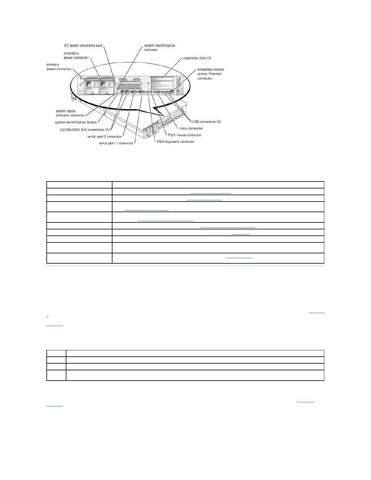
l Back-panel connectors including video, keyboard, mouse, two serial, two USB, embedded remote access Ethernet, and two NICs.
l Front-panel connectors including video, keyboard, mouse, and USB.
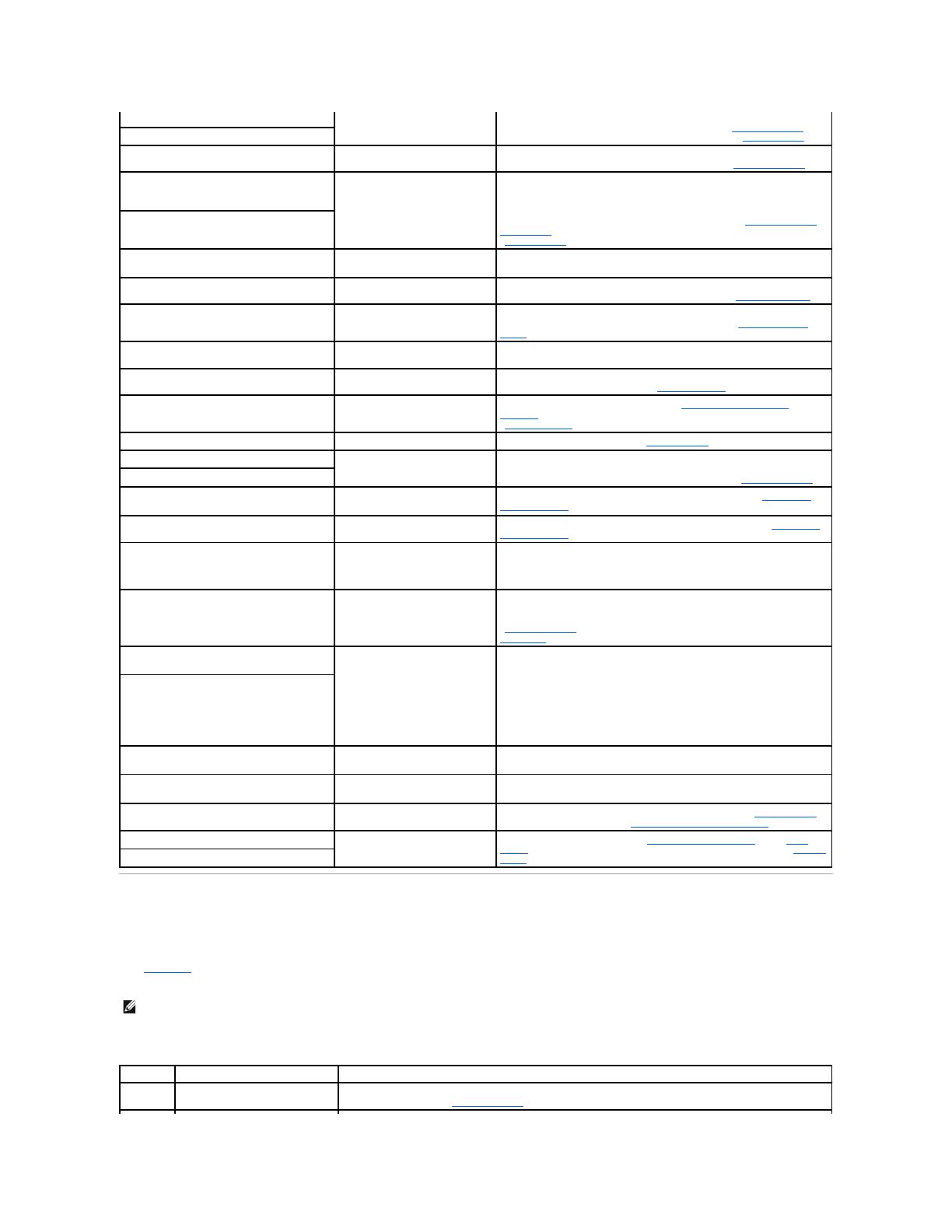
For more information about specific features, see "Technical Specifications."
Software Features
The following software is included with your system:
l A System Setup program for quickly viewing and changing system configuration information. For more information on this program, see "Using the
System Setup Program."
l Enhanced security features, including a system password and a setup password, available through the System Setup program.
l System diagnostics for evaluating system components and devices. For information on using the system diagnostics, see "Running the System
Diagnostics."
l Video drivers for displaying many application programs in high-resolution modes. For more information on drivers, see "Using the Dell OpenManage
Server Assistant CD" in your User's Guide.
l SCSI device drivers that allow the operating system to communicate with devices attached to the integrated SCSI subsystem. For more information on
drivers, see "Installing and Configuring SCSI Drivers" in your User's Guide.
l Systems management software and documentation.
l Optional solutions software for web hosting, caching, or load balancing. See your solutions software documentation for more information.
Supported Operating Systems
l Microsoft®Windows®2000 Server and Advanced Server
l Windows NT®4.0 Server, Enterprise Edition
l Red Hat Linux 7.x, or later
Service Features
The system includes the following service features to make troubleshooting and repair easy and effective, in most cases without tools or service aids:
l System diagnostics are available on the utility partition, which checks for hardware problems (if the system can boot). The diagnostics can also be
installed onto diskettes from the Dell OpenManage Server Assistant CD.
l Optional systems management hardware and software, which monitors temperatures and voltages throughout the system and notifies you if the
system overheats, if a system cooling fan malfunctions, if a microprocessor overheats, or if a power supply or VRM fails. For information about the
systems management option, see your systems management software documentation.
l The system simplifies removing and replacing components. You can replace microprocessors or memory modules without removing the system board.
The SCSI backplane board and hard-drive carriers eliminate the extensive cabling and drive configuration usually required for a SCSI subsystem.
Power Protection Devices
A number of devices are available to protect your system from the effects of power problems such as power surges, transients, and power failures. The
following subsections describe some of these devices.
Surge Protectors
Surge protectors are available in a variety of types and usually provide a level of protection commensurate with the cost of the device. Surge protectors
prevent overvoltage spikes, such as those that may occur during an electrical storm, from entering the system through the electrical outlet. Surge protectors
do not offer protection against brownouts, which occur when the voltage drops more than 20 percent below the normal AC line voltage level.
Line Conditioners
Line conditioners go beyond the overvoltage protection of surge protectors. Line conditioners keep a system's AC power source voltage at a fairly constant
level and provide protection from brownouts of short duration. Because of this added protection, line conditioners cost more than surge protectorsup to
several hundred dollars. However, these devices cannot protect against a complete loss of power.
Uninterruptible Power Supplies
UPS systems offer the most complete protection against variations in power because they use battery power to keep the system running when AC power is
unavailable or unusable. The battery is charged by the AC power while it is available so that once AC power is lost, the battery can provide power to the
system for a limited amount of timefrom 15 minutes to an hour or sodepending on the UPS system.
UPS systems that provide only 5 minutes of battery power allow you to conduct shutdown of the system but are not intended to provide continued operation.
Use surge protectors with all UPS systems, and ensure that the UPS systems are UL safety approved.
Other Documents You May Need
Besides this document, the following documentation is included with your system:
l The Setting Up Your System document provides general instructions for setting up your system.
l The User's Guide describes system features, technical specifications, and the System Setup program.
l The Installation and Troubleshooting Guide describes how to install, troubleshoot, and upgrade your system.
l The systems management software documentation describes the features, requirements, installation, and basic operation of the system management
software. See the software's online help for information about the alert messages issued by the software.
l Operating system documentation describes how to install (if necessary), configure, and use the operating system software.
l Documentation included with any options you purchased separately from the system, which provides information you need to configure and install these
options in your system.
You may also have the following documents.
l Documentation updates are sometimes included with the system to describe changes to the system or software.
l The Rack Installation Guide describes how to unpack, set up, and install your system in a rack.
l Optional solutions software documentation for web hosting, caching, or load balancing information.
l Technical information filessometimes called "readme" filesmay be installed on the hard drive to provide last-minute updates about technical changes
to the system or advanced technical reference material intended for experienced users or technicians.
Technical Specifications
The System Information document provides important safety and regulatory information. Warranty information might be included within this document or
as a separate document.
NOTE: Always read these updates before consulting any other documentation because the updates often contain information that supersedes
the information in the other documents.
Microprocessor
Microprocessor type
up to two Intel Xeon microprocessors with a minimum
internal operating frequency of at least 1.8 GHz
Front-side bus (external) speed
400 MHz
Internal cache
512 KB cache
Math coprocessor
internal to microprocessor
Expansion Bus
Bus type
PCI/PCI-X
Expansion slots
3 dedicated PCI/PCI-X (full-length, 64-bit, up to 133
MHz; 2 slots on bus 1, and 1 slot on bus 2
Memory
Architecture
72-bit ECC PC-1600 DDR SDRAM DIMMs, with 2-way
interleaving
Memory module sockets
six 72-bit wide 184-pin DIMM sockets
Memory module capacities
128-, 256-, 512 MB, or 1-GB registered SDRAM DIMMs,
rated for 200-MHz DDR operation
Minimum RAM
256 MB
Maximum RAM
6 GB
Drives
Diskette drive
3.5-inch, 1.44-MB diskette drive
SCSI hard drives
up to five 1-inch, internal Ultra3 SCSI
CD or DVD drive
one IDE CD or DVD drive
Ports and Connectors
Rear:
Serial
two 9-pin connectors
USB
two 4-pin connectors
  • Page 1 1
  • Page 2 2
  • Page 3 3
  • Page 4 4
  • Page 5 5
  • Page 6 6
  • Page 7 7
  • Page 8 8
  • Page 9 9
  • Page 10 10
  • Page 11 11
  • Page 12 12
  • Page 13 13
  • Page 14 14
  • Page 15 15
  • Page 16 16
  • Page 17 17
  • Page 18 18
  • Page 19 19
  • Page 20 20
  • Page 21 21
  • Page 22 22
  • Page 23 23
  • Page 24 24
  • Page 25 25
  • Page 26 26
  • Page 27 27
  • Page 28 28
  • Page 29 29
  • Page 30 30
  • Page 31 31
  • Page 32 32
  • Page 33 33
  • Page 34 34
  • Page 35 35
  • Page 36 36
  • Page 37 37
  • Page 38 38
  • Page 39 39
  • Page 40 40
  • Page 41 41
  • Page 42 42
  • Page 43 43
  • Page 44 44
  • Page 45 45
  • Page 46 46
  • Page 47 47
  • Page 48 48
  • Page 49 49
  • Page 50 50
  • Page 51 51
  • Page 52 52
  • Page 53 53
  • Page 54 54
  • Page 55 55
  • Page 56 56
  • Page 57 57
  • Page 58 58
  • Page 59 59
  • Page 60 60
  • Page 61 61
  • Page 62 62
  • Page 63 63
  • Page 64 64
  • Page 65 65

Dell PowerEdge 2650 User manual

Category
Server barebones
Type
User manual
This manual is also suitable for

Ask a question and I''ll find the answer in the document

Finding information in a document is now easier with AI