Page is loading ...

T
T
S
S
L
L
M
M
Synthesized Wireless Radio Modem
242-22w0-XYZ
User Manual
001-2200-000 pdf | 001-2200-101 print
Last updated January 2008
Copyright 2007 CalAmp DataCom

REVISION HISTORY
2006 Aug FCC Release
2006 Dec Preliminary User Release
2007 Jan Manual Release
2007 Jan Revision 1: added TSLM dimension diagram
2007 Mar Revision 2: corrected drawings for Figures 4-4 & 4-5, added ID number incrementing
info to Section 7.2.3
2008 Jan Revision 3: Added Channel Selection information, Section 5.2.9.1

TABLE OF CONTENTS
S
S
E
E
C
C
T
T
I
I
O
O
N
N
1
1
–
–
P
P
R
R
E
E
F
F
A
A
C
C
E
E........................................................................................................5
1.1 COPYRIGHT NOTICE................................................................................................. 5
1.2 WARNING RF EXPOSURE........................................................................................... 5
S
S
E
E
C
C
T
T
I
I
O
O
N
N
2
2
–
–
P
P
R
R
O
O
D
D
U
U
C
C
T
T
O
O
V
V
E
E
R
R
V
V
I
I
E
E
W
W ...................................................................................... 6
2.1 MODULE IDENTIFICATION.........................................................................................6
2.2 GENERAL DESCRIPTION............................................................................................6
2.2.1 Physical Description .............................................................................................. 6
2.2.2 Features and Benefits............................................................................................6
2.2.3 Product Range...................................................................................................... 7
2.3 PART NUMBER BREAKDOWN...................................................................................... 7
2.4 RELATED PRODUCTS AND STANDARD ACCESSORIES.................................................... 7
2.4.1 TSLM Programming Kit .......................................................................................... 7
2.4.2 Miscellaneous Accessories...................................................................................... 7
2.4.3 Infrastructure....................................................................................................... 7
2.4.4 Antenna .............................................................................................................. 8
S
S
E
E
C
C
T
T
I
I
O
O
N
N
3
3
–
–
A
A
P
P
P
P
L
L
I
I
C
C
A
A
T
T
I
I
O
O
N
N
S
S
A
A
N
N
D
D
A
A
R
R
C
C
H
H
I
I
T
T
E
E
C
C
T
T
U
U
R
R
E
E.................................................................. 9
3.1 APPLICATION DETAILS .............................................................................................9
3.1.1 Generic Connectivity ............................................................................................. 9
3.1.2 SCADA Systems ...................................................................................................9
3.1.3 Telemetry Systems ............................................................................................... 9
3.1.4 Information Systems............................................................................................. 9
3.2 NETWORK ARCHITECTURE ........................................................................................ 9
3.2.1 Point-to-Point..................................................................................................... 10
3.2.2 Point-to-Multipoint.............................................................................................. 10
3.2.3 Multiple Point-to-Point......................................................................................... 10
3.2.4 Peer-to-peer ...................................................................................................... 10
3.2.5 Store and Forward .............................................................................................. 10
S
S
E
E
C
C
T
T
I
I
O
O
N
N
4
4
–
–
S
S
Y
Y
S
S
T
T
E
E
M
M
P
P
L
L
A
A
N
N
N
N
I
I
N
N
G
G
A
A
N
N
D
D
D
D
E
E
S
S
I
I
G
G
N
N .................................................................... 11
4.1 UNDERSTANDING RF PATH REQUIREMENTS .............................................................. 11
4.2 SELECTING ANTENNAS........................................................................................... 11
4.2.1 Antenna Gain..................................................................................................... 12
NETWORK CONFIGURATIONS............................................................................................ 13
4.2.2 Basic Network Configuration................................................................................. 13
4.2.3 T-96SR Master Network Configuration for Higher Duty Cycle Applications.................... 14
4.2.4 T-Base Network Configuration .............................................................................. 15
4.2.5 Network Configuration Using a T-Base Repeater...................................................... 16
4.2.6 Network Configuration Using a TSLM for Monitoring Online Diagnostics....................... 17
S
S
E
E
C
C
T
T
I
I
O
O
N
N
5
5
–
–
G
G
E
E
T
T
T
T
I
I
N
N
G
G
S
S
T
T
A
A
R
R
T
T
E
E
D
D........................................................................................ 18
5.1 UNPACKING .......................................................................................................... 18
5.2 QUICK START GUIDE.............................................................................................. 18
5.2.1 General............................................................................................................. 18
5.2.2 Compatibility...................................................................................................... 18
5.2.3 Installation ........................................................................................................ 18
5.2.4 Antenna ............................................................................................................ 18
5.2.5 Power Requirements ........................................................................................... 18
5.2.6 RS-232 Port....................................................................................................... 19
5.2.7 RS-232 Interface Signal....................................................................................... 19
5.2.8 Connector Pin out ............................................................................................... 19
5.2.9 Field Programming Software................................................................................. 20
5.2.19.1 Channel Selection ............................................................................................ 21
5.2.10 RTS/CTS or DOX Operation............................................................................... 20
5.2.11 RTS/CTS delays .............................................................................................. 21
5.2.12 Duty Cycle...................................................................................................... 21
5.2.13 LED Indicators ................................................................................................ 21

TABLE OF CONTENTS
5.2.14 Setup Mode........................................................................................................ 22
5.2.15 Default Data Settings....................................................................................... 22
5.2.16 Diagnostics..................................................................................................... 22
5.2.17 TSLM Product Warranty Information................................................................... 23
5.2.18 Factory Technical Support................................................................................. 23
S
S
E
E
C
C
T
T
I
I
O
O
N
N
6
6
–
–
U
U
S
S
A
A
G
G
E
E
A
A
N
N
D
D
M
M
A
A
I
I
N
N
T
T
E
E
N
N
A
A
N
N
C
C
E
E............................................................................ 24
6.1 USAGE ................................................................................................................. 24
6.2 TSLM MOUNTING DIMENSIONS................................................................................ 24
6.2.1 Connector Pinout ................................................................................................ 25
6.2.2 Wire Connection (DOX)........................................................................................ 26
6.2.3 Power up........................................................................................................... 26
6.2.4 LED Indicators.................................................................................................... 26
6.2.5 Default Data Settings.......................................................................................... 27
6.2.6 Link Establishment and BER Testing ...................................................................... 27
6.3 MAINTENANCE AND DIAGNOSTICS........................................................................... 27
6.3.1 Online diagnostics............................................................................................... 27
6.3.2 Offline Diagnostics.............................................................................................. 28
6.3.3 Remote Commands............................................................................................. 28
S
S
E
E
C
C
T
T
I
I
O
O
N
N
7
7
–
–
F
F
I
I
E
E
L
L
D
D
P
P
R
R
O
O
G
G
R
R
A
A
M
M
M
M
I
I
N
N
G
G
S
S
O
O
F
F
T
T
W
W
A
A
R
R
E
E................................................................... 29
7.1 INTRODUCTION..................................................................................................... 29
7.2 INSTALLATION ...................................................................................................... 29
7.2.2 Version Request ................................................................................................. 36
7.2.3 READ / Copy / Program TSLM PARAMETERS ........................................................... 36
7.2.4 Read Programmable Settings Settings ................................................................... 37
7.2.5 Port Settings...................................................................................................... 37
7.2.6 Port Statistics..................................................................................................... 39
7.2.8 Offline Diagnostics.............................................................................................. 43
7.2.9 Online Diagnostics .............................................................................................. 46
7.2.10 Diagnostic IDs, Alarms and Filters ......................................................................... 48
7.2.11 User Test........................................................................................................... 50
7.2.13 Array Test.......................................................................................................... 54
7.2.14 Program Firmware............................................................................................... 56
7.2.15 ASCII / HEX TERMINAL........................................................................................ 56
S
S
E
E
C
C
T
T
I
I
O
O
N
N
8
8
–
–
S
S
P
P
E
E
C
C
I
I
F
F
I
I
C
C
A
A
T
T
I
I
O
O
N
N
S
S .......................................................................................... 58
8.1 GENERAL SPECIFICATIONS ..................................................................................... 58
8.2 TRANSMITTER SPECIFICATIONS .............................................................................. 59
8.3 RECEIVER SPECIFICATIONS .................................................................................... 59
8.4 INTERFACE SPECIFICATIONS................................................................................... 59
8.5 ENVIRONMENTAL SPECIFICATIONS .......................................................................... 59
8.6 REGULATORY AND INDUSTRY SPECIFICATIONS ......................................................... 60
S
S
E
E
C
C
T
T
I
I
O
O
N
N
9
9
–
–
S
S
E
E
R
R
V
V
I
I
C
C
E
E
A
A
N
N
D
D
S
S
U
U
P
P
P
P
O
O
R
R
T
T................................................................................. 61
9.1 PRODUCT WARRANTY, RMA AND CONTACT INFORMATION........................................... 61
9.2 RMA REQUEST....................................................................................................... 61
9.3 PRODUCT DOCUMENTATION.................................................................................... 61
9.4 TECHNICAL SUPPORT ............................................................................................. 61
S
S
E
E
C
C
T
T
I
I
O
O
N
N
1
1
0
0
–
–
D
D
a
a
t
t
a
a
T
T
e
e
l
l
e
e
m
m
e
e
t
t
r
r
y
y
W
W
a
a
r
r
r
r
a
a
n
n
t
t
y
y ............................................................................. 62

SECTION 1
um_tslm rev3.doc
Page 5 of 62
S
S
E
E
C
C
T
T
I
I
O
O
N
N
1
1
–
–
P
P
R
R
E
E
F
F
A
A
C
C
E
E
1.1 COPYRIGHT NOTICE
©2007 CalAmp DataCom. All Rights Reserved.
This manual covers the operation of the TSLM Synthesized Radio Modems. Specifications
described are typical only and are subject to normal manufacturing and service tolerances.
CalAmp DataCom reserves the right to modify the equipment, its specification or this
manual without prior notice, in the interest of improving performance, reliability or
servicing. At the time of publication all data is correct for the operation of the equipment at
the voltage and/or temperature referred to. Performance data indicates typical values
related to the particular product.
This manual is copyright by CalAmp DataCom. All rights reserved. No part of the
documentation or information supplied may be divulged to any third party without the
express written consent of CalAmp DataCom.
Products offered may contain software which is proprietary to CalAmp DataCom. The offer
of supply of these products and services does not include or infer any transfer of ownership.
1.2 WARNING RF EXPOSURE
The radio equipment described in this user manual emits low level radio frequency energy.
Professional installation is required. The concentrated energy may pose a health hazard.
This device is intended for Fixed installation conditions. Do not allow persons to come within
6.6 feet of non-directional antenna and 20 feet from the front of directional antennas when
the transmitter is operating.

SECTION 2
um_tslm rev3.doc
Page 6 of 62
S
S
E
E
C
C
T
T
I
I
O
O
N
N
2
2
–
–
P
P
R
R
O
O
D
D
U
U
C
C
T
T
O
O
V
V
E
E
R
R
V
V
I
I
E
E
W
W
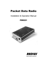
2.1 MODULE IDENTIFICATION
The module identification number is a random, unique serial number (SN) printed on the
shipping box and the model label on the side of the module.
Figure 2.1 - Module Identification Label
2.2 GENERAL DESCRIPTION
The Dataradio TSLM is a transparent, real-time wireless modem designed to replace wire
lines in SCADA, telemetry, and any other information and control applications that utilize
RS-232 serial data messaging. The TSLM uses advanced digital modulation and signal
processing techniques to achieve exceptionally high throughput efficiency using licensed
narrow band radio channels.
The TSLM is available in many frequency bands and regulatory formats, to suit spectrum
band requirements in various continental regions. The range is designed for both fixed point
to point, and multiple address or point to multipoint systems.
2.2.1 Physical Description
The TSLM consists of a logic printed circuit board (PCB) that includes the modem circuitry
and a separate radio module. The unit is housed in a nickel-plated, formed steel case. The
front panel includes the DE-15 data connector and a BNC antenna connector, as well as two
multi-colored LED indicators. Power connections are made through the DE-15 data
connector. The unit is not hermetically sealed and should be mounted in a suitable
enclosure where dust and/or a corrosive atmosphere are anticipated. There are no external
switches or adjustments. Operating parameters are set using TSLM Programming Software.
2.2.2 Features and Benefits
Data speeds of 4800 to 9600 bps in 12.5 kHz channels
Standard RS-232 interface with RTS/CTS or Data Operated Transmit (DOX) operation
Built-in 8 channel synthesized radio transceiver for VHF and UHF bands
Power output 1-5 W (software controlled)
Half duplex or simplex operation
Online diagnostics monitoring
Offline local and remote diagnostics

SECTION 2
um_tslm rev3.doc
Page 7 of 62
2.2.3 Product Range
The TSLM is available in UHF and VHF frequency bands. For a break down of available part
numbers and their frequency ranges, see Table 2.3.
2.3 PART NUMBER BREAKDOWN
242-22w0-XY0(M)
Table 2.3
Description of Part Number (reference part number equation above)
W X Y (M)
1 VHF 2 406-422 MHz 1 12.5 kHz Mounting Bracket
4 UHF 3 414-430 MHz
5 450-470 MHz
6 150-174 MHz
7 137-162 MHz
2.4 RELATED PRODUCTS AND STANDARD ACCESSORIES
2.4.1 TSLM Programming Kit
Table 2.3
Programming Kit Descrption: 250-2200-001
Programming Kit 250-2200-001 (includes the following):
Start Up Disc 002-2200-100
Programming Software 039-2200-210
Manual(s) 001-2200-000 pdf 001-2200-101 print
Programming Cable 697-4006-406
2.4.2 Miscellaneous Accessories
Table 2.4
Accessories
Description Part Number
Mounting Bracket Kit 250-2000-005
Unterminated Application Cable 023-3276-007
Terminated Application Cable 697-0000-001
2.4.3 Infrastructure
The TSLM is based on the Dataradio T-96SR platform giving user’s the versatility to design
systems with the T-96SR functioning as a Master, T-Base and Repeater and TSLM units
providing economical remote monitoring and high availability system operation. The TSLM
and T-96SR share radio modulation scheme, on-line and offline diagnostics, and data
connector pin-out compatibility.

SECTION 2
um_tslm rev3.doc
Page 8 of 62
Table 2.5
T-96SR Infrastructure
T-96SR Model Number Breakdown
242-40W6-XYZ(F)
W X Y Z (UHF Units) F (optional)
1 VHF 0 406 – 430 MHz 0 406 – 422 MHz
4 132 – 150 MHz 1 414 – 430 MHz
5 450 - 470 MHz
4 UHF
6 150 – 174 MHz
1 12.5 kHz
Fan Option
2.4.4 Antenna
Yagi Antenna Kit Description Part Number
* 138-143 MHz, 6.5 dB 250-0211-007
* 138-143 MHz, 9.5 dB 250-0211-010
* 143-148 MHz, 6.5 dB 250-0211-107
* 143-148 MHz, 9.5 dB 250-0211-110
* 148-152 MHz, 6.5 dB 250-0211-207
* 148-152 MHz, 9.5 dB 250-0211-210
* 152-157 MHz, 6.5 dB 250-0211-307
* 152-157 MHz, 9.5 dB 250-0211-310
* 157-163 MHz, 6.5 dB 250-0211-407
* 157-163 MHz, 9.5 dB 250-0211-410
* 163-169 MHz, 6.5 dB 250-0211-507
* 163-169 MHz, 9.5 dB 250-0211-510
* 169-174 MHz, 6.5 dB 250-0211-607
* 169-174 MHz, 9.5 dB 250-0211-610
450-470 MHz, 7 dB 250-0241-507
450-470 MHz, 10 dB 250-0241-510
*Antenna Kit Feedline
25 feet antenna feedline, (LMR400), N Male) 250-0200-025
50 feet antenna feedline, (LMR400, N Male) 250-0200-055
*Requires antenna feedline

SECTION 3
um_tslm rev3.doc
Page 9 of 62
S
S
E
E
C
C
T
T
I
I
O
O
N
N
3
3
–
–
A
A
P
P
P
P
L
L
I
I
C
C
A
A
T
T
I
I
O
O
N
N
S
S
A
A
N
N
D
D
A
A
R
R
C
C
H
H
I
I
T
T
E
E
C
C
T
T
U
U
R
R
E
E
3.1 APPLICATION DETAILS
The TSLM is designed to replace wire lines in SCADA, telemetry and control
applications. The RS-232 serial port allows direct connection to Programmable
Logic Controllers (PLCs) or Remote Terminal Units (RTUs).
3.1.1 Generic Connectivity
The TSLM is designed for SCADA and telemetry applications, and any other
applications that use ASCII or HEX communications protocols, and which
connect physically using the RS232 interface standard. Converters may be
used to adapt interface standards such as RS422/485 and others.
An ASCII protocol is any that consists of message strings formed from ASCII
characters, that being defined as a 10 or 11 bit block including start and stop
bits, 7 or 8 data bits and optional parity bits.
Many telemetry vendors utilize proprietary ASCII and HEX protocols, and also
common ‘open standard’ industry protocols such as DNP, MODBUS, BSAP,
Seimens and DF1 half duplex or DF1 radio.
3.1.2 SCADA Systems
A SCADA system is defined as one or more centralized control sites used to
monitor and control remote field devices over wide areas. Examples include
regional utilities monitoring and controlling networks over entire metropolitan
areas. Industry sectors include energy utilities, water and wastewater utilities,
and environmental groups.
3.1.3 Telemetry Systems
Dedicated telemetry control systems interconnect sequential devices either
where cabling is not practical or distances make cable connections
impractical.
3.1.4 Information Systems
Public Information systems include monitoring applications such as vehicle
flow, travel time, and meteorological stations.
3.2 NETWORK ARCHITECTURE
This section briefly discusses network design, including basic network types,
interfacing modems and DTE, data protocols for efficient channel operation,
addressing and repeaters.

SECTION 3
um_tslm rev3.doc
Page 10 of 62
3.2.1 Point-to-Point
A point-to-point network is the simplest of all networks, and may be used for
connecting a pair of PC's, a host computer and a terminal, a SCADA master
and one remote, mobile applications like in-vehicle GPS receivers to base
stations, or a wide variety of other networking applications.
3.2.2 Point-to-Multipoint
A Point-to-Multipoint network is a common network type used in SCADA or
other polling systems. The single master station communicates with any
number of remotes and controls the network by issuing polls and waiting for
remote responses. Individual remotes (DTE) manage addressing and respond
when their individual addresses are queried. The DTE unit addresses are
maintained in a scanning list stored in the host program or master terminal
device at the SCADA host site. The communications equipment is transparent
and does not interact with specific remotes; all data is coupled to the host on
a single data line (such a network is commonly used with synchronous radio
modems and asynchronous radio modems).
3.2.3 Multiple Point-to-Point
A multiple point-to-point is similar to the point-to-multipoint system except
the SCADA host has multiple serial ports that are directed to different
geographic areas in the SCADA system.
3.2.4 Peer-to-peer
A Peer-to-Peer network is generally used for device to device communications
among a number of stations. This network requires full addressing capability
on the part of the data equipment (DTE). If the distances involved for any link
or links are too great for a single radio hop, they can be extended by means
of repeaters without affecting the basic network design.
3.2.5 Store and Forward
Store and Forward is a common technique where a data transmission is sent
from one device to a receiving device but first passes through a relaying
device. The device is typically an RTU or PLC used by the message service to
store the received message then it transmits the message to the intended
recipient.

SECTION 4
um_tslm rev3.doc
Page 11 of 62
S
S
E
E
C
C
T
T
I
I
O
O
N
N
4
4
–
–
S
S
Y
Y
S
S
T
T
E
E
M
M
P
P
L
L
A
A
N
N
N
N
I
I
N
N
G
G
A
A
N
N
D
D
D
D
E
E
S
S
I
I
G
G
N
N
4.1 UNDERSTANDING RF PATH REQUIREMENTS
Radio waves are propagated when electrical energy produced by a radio
transmitter is converted into magnetic energy by an antenna. Magnetic waves
travel through space. The receiving antenna intercepts a very small amount
of this magnetic energy and converts it back into electrical energy that is
amplified by the radio receiver.
A radio modem requires a minimum amount of received RF signal to operate
reliably and provide adequate data throughput. In most cases, spectrum
regulators will define or limit the amount of signal that can be transmitted.
Transmitted power decays with distance and other factors as it moves away
from the transmitting antenna.
Other factors that will decay a signal include obstructions such as hills,
buildings and foliage, and the horizon – i.e. the bulge between two points of
earth. Minimal signal degradation may occur as a result of environmental
conditions such as fog, rain, dust storms or other similar factors.
There are several methods to ascertain the available RF coverage from a
transmitting station. This can be accomplished by:
A. Using basic formulas to calculate the theoretically available signal –
allowing for free space path loss due to distance and equipment signal loss
B. Using sophisticated software to build earth terrain models and apply other
correction factors such as earth curvature and the effects of obstructions
C. Actual in-field signal strength testing
As good design practice, CalAmp DataCom recommends the results of at least
two of these modes be considered to design a radio path with one of the
results being the actual in-field signal strength test.
4.2 SELECTING ANTENNAS
Antennas come in a variety of shapes and sizes, but fall into two basic
categories: directional and omni-directional. Directional antennas are
designed to focus and radiate the RF energy in one specific direction.
Generally, in a point-to-point network, directional antennas will be used. In a
point-multipoint network, with a base station and a several remotes, the base
station will use an omni-directional antenna and the remotes will use
directional antennas. Figure 4.1 shows some antenna variations.

SECTION 4
um_tslm rev3.doc
Page 12 of 62
Omni directional antennas are designed to radiate the RF signal in a 360
degree pattern around the antenna. Short range antennas such as folded
dipoles and ground independent whips are used to radiate the signal in a ball
shaped pattern while high a gain omni such as a co-linear compress the RF
radiation sphere into the horizontal plane to provide a relatively flat disc
shaped pattern that travels further because more of the energy is radiated in
the horizontal plane.
Vertical dipoles are often mounted in pairs, or sometimes groups of 3 or 4, to
achieve even coverage and to increase gain. The vertical collinear usually
consists of several elements stacked one above the other to achieve similar
results.
Omni
(Vertical collinear )
Yagi Vertical Dipole
Figure 4.1- Antenna Types
4.2.1 Antenna Gain
Antenna gain is usually measured in comparison to a dipole. A dipole behaves
much like the filament of a flashlight bulb: it radiates energy in almost all
directions. One bulb like this would provide very dim room lighting. Add a
reflector capable of concentrating all the energy into a narrow angle of
radiation and you have a flashlight. Within that bright spot on the wall, the
light might be a thousand times greater than it would be without the reflector.
The resulting bulb-reflector combination has a gain of 1000, or 30 dB,
compared to the bulb alone. Gain can be achieved by concentrating the
energy both vertically and horizontally, as in the case of the flashlight and
Yagi antenna, or by reducing the vertical angle of radiation, leaving the
horizontal alone. In this case the antenna will radiate equally in all horizontal
directions, but will take the energy that otherwise would have gone skywards
and use it to increase the horizontal radiation.

SECTION 4
um_tslm rev3.doc
Page 13 of 62
NETWORK CONFIGURATIONS
4.2.2 Basic Network Configuration
A Basic Network configuration has the following characteristics:
Master station may be half duplex or simplex
Online diagnostics are not available in real time
Remote/local diagnostics and Online Diagnostics are available by
disconnecting the master PLC and substituting a PC running the TSLM
Field Programming Software utility or utilizing a monitor radio
Figure 4.2 Basic Network Configuration

SECTION 4
um_tslm rev3.doc
Page 14 of 62
4.2.3 T-96SR Master Network Configuration for Higher Duty Cycle Applications
Figure 4.3 T-96SR Master Network Configuration
A Network Using a T-96SR as Master configuration has the following
characteristics:
Recommended for higher duty cycle applications
Master station may be simplex or half duplex
The T-96SR will receive RTS/CTS or DOX mode communications from a
TSLM (The T-96SR will not transmit in DOX mode, only when RTS is
raised)

SECTION 4
um_tslm rev3.doc
Page 15 of 62
4.2.4 T-Base Network Configuration
A Network Using a T-Base configuration has the following characteristics:
Master station may be full duplex
1
, half duplex or simplex
The Online Diagnostics utility does not disrupt network activity
Remote/local diagnostics and statistics/control are available using the
Offline Diagnostics utility when connected to the Tx module
The T-Base outputs Online Diagnostic information that can be
processed by the Online Diagnostics utility or a user-supplied network
management program
The T-96SR provides high availability for systems requiring system
redundancy
Figure 4.4 T-Base Network Configuration with Diagnostics
1
Requires duplexer or dual antennas

SECTION 4
um_tslm rev3.doc
Page 16 of 62
4.2.5 Network Configuration Using a T-Base Repeater
A Network Using a T-Base Repeater has the following characteristics:
Master station and all remotes must be half duplex
The RTS/CTS delays for each TSLM in the system must be extended as
shown in Table 5.3
Figure 4.5 Network Using a T-Base Repeater

SECTION 4
um_tslm rev3.doc
Page 17 of 62
4.2.6 Network Configuration Using a TSLM for Monitoring Online Diagnostics
A Network Using a TSLM for Online Diagnostics configuration has the following
characteristics:
Master station may be half duplex or simplex
Accumulated online diagnostics are stored for a maximum of 10
stations are available at a monitoring site (monitoring site must be in
range of all remotes)
Online Diagnostics are available in real time at the monitoring site
Remote Offline Diagnostics, statistics, and control are available from
the monitoring site by temporarily disabling network activity (best if
using a Master Station Antenna System)
Figure 4.6 Network Using a TSLM for Online Diagnostics

SECTION 5
um_tslm rev3.doc
Page 18 of 62
S
S
E
E
C
C
T
T
I
I
O
O
N
N
5
5
–
–
G
G
E
E
T
T
T
T
I
I
N
N
G
G
S
S
T
T
A
A
R
R
T
T
E
E
D
D
5.1 UNPACKING
When ready for installation, carefully unpack your TSLM shipping carton and identify each
item as listed below:
One TSLM radio modem (with mounting plate if “M” option is ordered)
Quick Start Guide
5.2 QUICK START GUIDE
The Quick Start Guide is included in print with the TSLM.
5.2.1 General
The TSLM is a transparent, real-time wireless modem designed for use in VHF and UHF
telemetry and SCADA systems. Power output is 1-5 W programmable. Data rates are 4800 -
9600 bps (12.5 kHz channels). It contains an 8 channel, synthesized radio transceiver.
5.2.2 Compatibility
The TSLM is based on the Dataradio T-96SR platform giving users the versatility to design
systems with the T-96SR functioning as a Master or Base and repeater and TSLM units
providing economical remote monitoring stations. The TSLM and T-96SR share radio
modulation, on-line diagnostics, and data connector pin-out compatibility.
5.2.3 Installation
The TSLM should be mounted in a clean, dry location. The unit is not hermetically
sealed and must be protected against moisture, corrosive chemicals and high
dust levels.
5.2.4 Antenna
The antenna(s) used for this transmitter must be installed to provide a separation distance
of at least 141 cm (55.5 inches) for VHF models or 121 cm (47.6 inches) for UHF models
from all persons. The antenna must be designed for the frequency of operation and
mounted at an elevation sufficient to cover the distance required. The antenna feedline
should have a male BNC connection and requires an impedance of 50 ohms.
5.2.5 Power Requirements
The TSLM requires a filtered power source of 7.2 - 15 V with a 3 A rating. Power
connection is via the data connector as shown on the next page.

SECTION 5
um_tslm rev3.doc
Page 19 of 62
5.2.6 RS-232 Port
The TSLM is equipped with an RS-232 data port configured as DCE. It should be connected,
using a suitable shielded cable, to equipment configured as DTE.
5.2.7 RS-232 Interface Signal
Table 5.1
RS-232 Interface Signal
5.2.8 Connector Pin out
DTE connector is a DE-15 female
Figure 5.1 DE-15 Connector Pin-out
Table 5.2
DE-15 Pin Descriptions
DE-15 Pin Description
1 GND (Ground)
2 RxD (Receive Data)
3 TxD (Transmit Data)
4 Rx_TP (Receive baseband data test point)
5 RAW_BATT (12.5 Vdc nominal power supply)
6 GND (Ground)
7 CTS (Clear To Send)
8 RTS (Request To Send)
9 DCD (Data Carrier Detect)
10 RAW_BATT (12.5 Vdc nominal power supply)
11 CSO (Channel Select 0)
12 CS1 (Channel Select 1)
13 CS2 (Channel Select 2)
14 RSSI_OUT (Receive Signal Strength Indicator)
15 DTR_PGM (Program Mode Select)
Term Data Alternate
Voltage
On Space Asserted
+3 to +15V
Off Mark Dropped -3 to -15V

SECTION 5
um_tslm rev3.doc
Page 20 of 62
5.2.9 Field Programming Software
The TSLM is configured by means of the Field Programming Software (FPS)
(Part No. 039-2200-210). Channel frequencies for 8 channels are also selected using the
FPS.
The following parameters may be adjusted with the FPS:
• Channel 1 - 8 TX and RX frequencies
• Baud rate, word length, parity
• Timing parameters
• Diagnostics on/off
• Carrier detect threshold level
• Power output
In addition, the FPS provides the tools for test transmissions and allows test statistics to
be obtained and displayed. See the Programming Software on-line help file for details.
5.2.9.1 Channel Selection
Channel frequencies are programmed for 8 channels using the TSLM FPS. The
current operating channel is selected in one of two ways:
1. Utilizing hardware jumpers by strapping connection on the Data Port
Connector. There is a 10k ohm pull-up resistor on each line (CS0 to CS2)
(refer to Table 5.3).
2. By making changes with the TSLM FPS. Select the channel from the TSLM
Offline Diagnostics or User Test interface.
Table 5.3
Channel Selection
Channel CS2 CS1 CS0
1 gnd gnd gnd
2 gnd gnd open
3 gnd open
gnd
4 gnd open
open
5 open gnd gnd
6 open gnd open
7 open open
gnd
8 open open
open
5.2.10 RTS/CTS or DOX Operation
The unit operates transparently at the data speed selected by the Field Programming
Software.
In DOX mode, the TSLM will begin transmitting when data is ready to send (no RTS
signal required) and terminate when no data remains to be sent.
If RTS/CTS operation is selected, the DTE starts a data transfer by asserting RTS.
A CTS response is returned after the transmitter has been keyed and the remote modem
has had sufficient time to synchronize.
/