Page is loading ...

Owners Manual
Electrofeed
Universal Bale Feeder
3PT Linkage
Pt. No. 67359
Issue 0305
From Serial Number TLCD 05584
Head Office:
P.O. Box 2018
Hilton Highway, Washdyke
Timaru, New Zealand
Telephone (03) 688 2029
Facsimile (03) 688 2821
Australian Branch:
4B SIlverton Close
Laverton North 3026
Melbourne, Australia
Telephone (03) 9314-9666
Facsimile (03) 9314-6810


Electrofeed Contents
Page
Introduction
Acquisition & Warranty . . . . . . . . . . . . 2
The Owner’s Manual . . . . . . . . . . . . . . 2
Description of Machine Working Principle . . . . . . . . . . . . . . . . 3
Features . . . . . . . . . . . . . . . . . . . . . . . . . . . . . . . 3
Specification . . . . . . . . . . . . . . . . . . . . . . . . . . . . . . . 3
SAFETY - General Safety Symbols on Machine . . . . . . . . 4
Operator Safety . . . . . . . . . . . . . . . . . . 5
Be Prepared for Emergencies . . . . . . 5
Appropriate Dress . . . . . . . . . . . . . . . . 6
Transport This Machine Safely . . . . . . 6
Handle Agricultural Chemicals Safely . 7
Avoid High Pressure Fluids . . . . . . 7
Safe Working Practices . . . . . . . . . . . . 7
Practise Safe Maintenance . . . . . . . . . 8
SAFETY- Machine Specific
Hazard Points . . . . . . . . . . . . . . . . . . . 9
Safety Decals & Safety Guards . . . . . 11
Operation Attaching & Detaching . . . . . . . . . . . . . 12
Loading Round Bales . . . . . . . . . . . . . 13
Feeding Out Round Bales . . . . . . . . . 13
Loading & Feeding Out Square Bales 14
Warnings Specific to this Machine . . . 15
Maintenance Lubrication Chart . . . . . . . . . . . . . . . . . 16
Servicing . . . . . . . . . . . . . . . . . . . . . . . 16
Mechanical Adjustments Floor Chain Tension Settings . . . . . . . 17
Elevator Chain Tension Settings . . . . . 17
Fork Point Assemblies . . . . . . . . . . . . 17
Sprockets, Drive Dogs & Bearings . . . 18
Motor Mounts . . . . . . . . . . . . . . . . . . . 18
Storage . . . . . . . . . . . . . . . . . . . . . . . . . . . . . . . 18
Operator Notes . . . . . . . . . . . . . . . . . . . . . . . . . . . . . . . 19

2
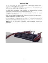
Introduction
Acquisition & Warranty
On delivery of your new Duncan Ag Electrofeed, Universal
Bale Feeder (3Pt Linkage), please check that the machine is
not damaged. In cases of shipping damage, please ask your
dealer to arrange for the appropriate claim to be lodged
immediately. Assemble any parts supplied loose and inspect
your machine with the aid of this manual to familiarise yourself
with its features. If you have any queries ask your dealer
straight away. The machine is covered by our 12 month
warranty on faulty parts, subject to normal use.
Record below the serial number of your machine and keep
it in a secure place to help trace the machine and assist
us when you order parts.
The Owner’s Manual
Your new Duncan Ag Electrofeed, Universal Bale Feeder, will
give long and efficient service if given normal care and
operated properly.
This owner’s manual is provided so that you can become
thoroughly familiar with the design of the machine and to
furnish information on correct operation, adjustment and
maintenance. Only persons well acquainted with these
guidelines should be allowed to use the equipment.
A separate illustrated parts section has been provided so that if
any parts are required your dealer will be able to supply them
by reference to part numbers. The manual is considered as
part of your machine and must remain with the machine when
it is sold.
Right and left hand references in this manual are
determined by standing behind the machine and facing in
the direction of travel.
Model: . . . . . . . . . . . . . . . . . . . . . . . . . . . . . . . . . . . . . .
Serial No: . . . . . . . . . . . . . . . . . . . . . . . . . . . . . . . . . . .
Owner: . . . . . . . . . . . . . . . . . . . . . . . . . . . . . . . . . . . . . .
. . . . . . . . . . . . . . . . . . . . . . . . . . . . . . . . . . . . . . . . . . . . .
. . . . . . . . . . . . . . . . . . . . . . . . . . . . . . . . . . . . . . . . . . . . .
Delivery Date: . . . . . . . . . . . . . . . . . . . . . . . . . . . . . . .
Dealer: . . . . . . . . . . . . . . . . . . . . . . . . . . . . . . . . . . . . . .
. . . . . . . . . . . . . . . . . . . . . . . . . . . . . . . . . . . . . . . . . . . . .
. . . . . . . . . . . . . . . . . . . . . . . . . . . . . . . . . . . . . . . . . . . . .
Disclaimer
Every effort has been made to
ensure that the information in this
manual was accurate and up to
date at the time of going to press.
Clough Agriculture Ltd reserves the
right to make subsequent changes
to the machine, where necessary,
without notification.
The Company will not be
responsible for any damage or
consequential loss arising out of
misinterpretation or failure to follow
recommended procedures. Nor will
it be liable for any damage caused
by or arising out of modification or
misuse of its product.
The owner has a responsibility to
protect himself and others by
observing all safety information
and by ensuring all operators are
well acquainted with the safety
information, trained in the correct
use of the machine and applying
safe work practices.

3
Description of Machine
The Duncan Ag Electrofeed, Universal Bale Feeder
(3Pt Linkage), will feed both round and square bales of various
sizes and composition. The elevator feeds out square bales of
various sizes, teasing the biscuits through the adjustable
spring tine frame at the top; the knife roller feeds round
bales without blocking due to the unique anti-wrap
deflector. The floor and elevator chains are heavy
duty zinc plated, the floor and elevator beds are of
metal and welded construction with hardwearing
plastic chain support strips bolted on. All drive
chains have spring tensioners to eliminate chain
adjustment. The forks are connected to the tractor, and
the hydraulic drive is coupled automatically to the feed bed
when inserted into the chassis prior to transport or feeding out.
Working Principle
The bale is loaded by reversing under it and then depositing it
onto the feedbed using the forks attached to the tractor. The
forks are reconnected to the feeder, automatically coupling the
hydraulic drive. The feedline for square bales is on the elevator
side and for round bales on the knife roller side. Choice of
feeding action is by direction of tractor hydraulics.
Features
z Handles many sizes and types of both round and
square bales.
z Fingertip electro/hydraulic controls
z Feeds out either side using unique teaser roller or
elevator
z Sheetmetal floor ensures that all leaf and loose
grain drops into windrow
z Handles all types of round bales and silage
z Self connecting hydraulic drive
z Built in loading forks with easy locking device
z
Heavy duty zinc floor chains
z
Baked on powder coat finish
z Self adjusting drive chains
z Sliding top link adjustment
Specification
Pt No. 67359
Issue 0305
Dimensions & Capacities
Bale Sizes (Max) Round 1800 Dia x 1350 (6’ x 4’ 6”)
Square 1200 x 1200 x 2750 (4’ x 4’ x 9’)
Weight (Unladen) 640kg
Height (Over Elevator) 1520
(Over Tine Frame in Released Position) 1904
Length 1740
Width 2930

4
Do not ride or allow passengers on the machine.
Under no circumstances are passengers to be permitted on
the machine while it is in operation or being transported. Any
footboards and/or footsteps are provided solely for the
purpose of preparing the machine for use.
Keep clothing and body extremities well clear of pinch
points while the machine is operating (seeding or
calibrating). Keep well clear of moving parts at all times.
These signs typically occur wherever trapping points exist.
These include drive chains, sprockets, shafts, wheels, discs,
pivot points, etc. Guards are provided with the machine for
safety reasons (where practical without compromising
machine performance). Ensure these are always fitted during
operation.
Always exercise extreme caution in the vicinity of sharp
edges and points.
Where possible guards are provided with the machine for
safety reasons (where practical without compromising
machine performance). Ensure these are always fitted during
operation.
Footboards, footsteps, drawbars and other machine
surfaces may be slippery when wet.
Apply extra caution in wet conditions and in the early morning
when surfaces are wet.
Keep Clear. (It is dangerous to be in this area when the
machine is operating.)
!
ATTENTION
On the machine important safety information is indicated by these symbols.
These highlight general safety aspects in regard to the machine rather than specific hazards.

5
Pt. No. 67359
Issue 0305
SAFETY - General
This section of the manual offers general guidelines
for the safe operation of machinery. It does not replace
local safety regulations. These guidelines were current at
the time of publication, but may be superseded by later
regulations.
Duncan Ag has made every effort to highlight all risks to
personnel or property. Owners and operators have a
responsibility to exercise care and safe work practices at
all times in the vicinity of the machine.
Owners are advised to keep up to date on safety issues
and to communicate these to all users of the machine.
Contact the Occupational Safety and Health Service
(OSH) for further information about general safety aspects.
If you have safety concerns specifically related to this
machine, contact your dealer immediately.
Operator Safety
Read this manual carefully before operating new
equipment. Learn how to use this machine safely.
Be thoroughly familiar with the controls and the proper use
of the equipment before using it.
Take careful note of all safety instructions both in this
manual and on the machine itself. Failure to comply with
instructions could result in personal injury and/or damage
to the machine.
Replace missing or damaged safety signs on the machine
and ensure that these remain clearly visible.
It is the owner’s responsibility to ensure that anyone
who operates, adjusts, lubricates, maintains, cleans or
uses the machine in any way has had suitable
instruction and is familiar with the information in this
manual (particularly with regard to safety aspects).
Operators and other users of the machine should be
aware of potential hazards and operating limitations.
Be Prepared for Emergencies
Keep a first aid kit and fire extinguisher handy.
Keep emergency numbers for doctors, ambulance,
hospital and fire department near your telephone.
N.B. Throughout this
manual important safety
information is indicated
by these symbols in the
margin:
A prohibition should
be observed under all
circumstances.
A warning indicates a
hazard that could
cause death or injury if
the warning is ignored.
A caution indicates a
hazard that may cause
damage to property if
the caution is ignored.

6
SAFETY - General (Continued)
Appropriate Dress
Wear close fitting clothing and avoid rings or other forms of
jewellery which could become caught in the machinery.
People with long hair must have it securely fixed and confined
close to the head.
Refer to local safety standards for protective clothing and
recommended safety equipment.
Transport This Machine Safely
Ensure that all linkage pins and security clips are fitted correctly.
With trailing machines tow with the drawbar only, as this is the
only safe towing point on the machine.
Always check that bystanders (especially children) are well clear
(front and rear) before starting and moving the tractor and the
machine.
Plan safe routes of travel, and be aware of power lines and
other roadside hazards. Take particular care when towing
implements on hillsides.
Do not ride or allow passengers on the machine.
This machine is not designed to carry passengers, and no riders
are permitted.
Road transport
On public roads,
• A speed of 30km/h must not be exceeded.
• Do not operate during the hours of darkness unless standard
lights are fitted and clearly visible. (This also applies when
visibility is limited, e.g., in foggy conditions.)
See the guidelines in the booklet on Overdimension Agricultural
Vehicles, issued by the Land & Transport Safety Authority.
Avoid tip-overs
Avoid holes, ditches and obstructions which may cause the
machine to tip over, especially on hillsides. Never drive near the
edge of a gully or steep embankment - it might cave in. Slow
down for hillsides, rough ground and sharp turns.

7
SAFETY - General (Continued)
Handle Agricultural Chemicals Safely
All farm chemicals should be stored, used, handled and
disposed of safely and in accordance with the
supplier’s/manufacturer’s recommendations.
Read the product label before using, noting any warnings
or special cautions, including any protective clothing or
equipment that may be required, ie. respirtor.
Do not eat or smoke while handling sprays, fertilisers, coated
seeds, etc. Afterwards, always wash your hands and face
before you eat, drink, smoke, or use the toilet.
Store sprays, fertilisers, coated seeds, etc. out of reach of
children and pets, and away from food and animal feeds.
Any symptoms of illness during or after using chemicals
should be treated according to the supplier’s/manufacturer’s
recommendations. If severe, call a physician or get the
patient to hospital immediately. Keep the container and/or
label for reference.
Avoid High Pressure Fluids
Avoid any contact with fluids leaking under pressure, because
the fluids can penetrate the skin surface.
Any fluid which penetrates the skin, will need to be removed
immediately by a medical expert. Seek specialist advice on
this type of injury.
Relieve the pressure before disconnecting any hydraulic or
other lines. Make all repairs and tighten all fittings before
re-connection to pressurised fluid.
Keep your hands and body away from any pinholes or high
pressure jets. Search for leaks with a piece of cardboard
instead of using your hand directly.
Safe Work Practices
All farm machinery is potentially dangerous and should be
treated with caution and respect.
Before starting the machine, ensure that all controls are placed
in neutral and that bystanders are well clear. Check that the
guards have been securely fitted and that any adjustments
have been made correctly.
Where possible, disconnect or isolate the drive mechanism to
the implement. Lower the machine onto the ground when not
in use.
Pt. No. 67359
Issue 0305

8
SAFETY - General (Continued)
Practise Safe Maintenance
Keep the machine in safe working condition. Routine
maintenance and regular servicing will help reduce risks and
prolong the life of the machine.
General Maintenance
Accidents occur most frequently during servicing and repair.
The following general rules must be followed when maintaining
or working with machinery:
• All operating and maintenance manuals must be read
before and referred to while using or servicing any piece of
equipment.
• Turn off all machinery power sources and isolate the
machine before making adjustments, doing lubrication,
repairs or any other maintenance on the machine.
• Ensure that the machine hydraulics are disconnected from
the power source.
• Wear gloves when handling components with cutting
edges, such as any ground cutting components.
• Beware of hazards created by springs under tension or
compression when dismantling or maintaining the
machine.
• It is recommended that you clean the machine with a water
blaster or similar apparatus before commencing
maintenance.
Make Sure the Machine is Well Supported
When machinery is fitted with hydraulics, do not rely on the
hydraulics to support the machine. During maintenance or while
making adjustments under the machine, always lock the
hydraulics and support the machine securely. Place blocks or
other stable supports under elevated parts before working on
these.
Electrical Maintenance
Disconnect the electrical supply from the tractor before doing
any electrical maintenance.
Welding
With electronic equipment in modern tractors it is advisable to
disconnect the machine from the tractor, or at least disconnect
the alternator and battery before attempting any welding.
Use Only Genuine Spare Parts
Unauthorised modifications or non-genuine spare parts may be
hazardous and impair the safe operation and working life of the
machine.
Excess lubricants must be disposed of safely so as not to
become a hazard.

9
Pt. No. 67359
Issue 0305
SAFETY - Machine Specific
This section of the manual gives specific guidelines for
the safe operation of the Vineyard Seeder.
These guidelines were current at the time of publication, but
may be superseded by later circumstances. They do not
necessarily cover every possible hazard and must be read in
conjunction with the SAFETY - General section (Page 4 - 8).
Hazard Points on the Vineyard Seeder
The lists below are not all-inclusive and serve only to highlight
the more obvious areas of risk.
The decals attached to the machine are a general reminder
that there are hazardous areas on the machine, rather than
specifically highlighting all possible hazards.
For decal locations on machine, refer Page 11.
No Ride
Passengers are not permitted anywhere on the machine.
Pinch Points/Moving Parts
Hazardous areas include:
• Knife roller blades.
• Floor chains and sprockets.
• Elevator chains and sprockets.
• Floor drive motor sprockets and chains.
• Elevator drive motor sprockets and chains.
• Knife roller drive chains.
Sharp Points
Hazardous areas include:
• Floor chains spikes
• Elevator blades
• Knife roller blades.
Keep Clear
Hazardous areas include:
• Between headstock and mainframe.
• Immediately adjacent to the underneath of the elevator
frame.
• Immediately adjacent to the knife roller.

10
SAFETY - Machine Specific
(Continued)
Hazard Points on the Bale Feeder
(Continued)
Drive Chain Guard, Floor Chains & Elevator
To prevent hands, etc getting caught in drive chains, these
guards are attached with set screws. These guards must be
fitted while the machine is in use.
Warning: Access to pinch points is still possible from
underneath or behind the guards.
Elevator Front Guard
To prevent hands, etc getting caught in floor drive chains and
tine frame spring mechanism, this area is provided with a
cover attached with wing nuts. This guard and fastener must
be fitted while the machine is in use.
Warning: Access to pinch points is still possible from
underneath or behind the guards.
Knife Roller Chain Guard
To prevent hands, etc getting caught in the knife roller chain
and chain tensioner. This plastic guard is retained with a wing
nut. This guard and fastener must be fitted while the machine
is in use.
For guard locations on machine, refer Page 11.
Transport
Ensure fork lock hook is engaged prior to transport.
Maintenance
Refer Page 16-18 for reference to the Care & Maintenance
section of the manual.
Lubrication
Refer Page 16 for reference to the Lubrication section of the
manual.

11
Pt. No. 67359
Issue 0305
SAFETY - Machine Specific (Continued)
Safety Decals & Safety Guards
Item Decal/Guard Cross Reference Qty.
1 ‘No Ride’ Refer Page 9 Pt N
o
43906 2
2 ‘Pinch Point/Moving Parts’ Refer Page 9 Pt N
o
43901 2
3 ‘Pinch Point/Moving Parts’ Refer Page 9 Pt N
o
43907 4
4 ‘Sharp Points’ Refer Page 9 Pt N
o
43908 4
5 “Keep Clear” Refer Page 9 Pt N
o
43909 1
6 Guard RH Refer Page 10 & 16/17 Pt N
o
31554 1
7 Front Elevator Guard Refer Page 10 & 16/17 Pt N
o
32128 1
8 Rear Elevator Guard Refer Page 10 & 16/17 Pt N
o
32126 1
9 Rear Elevator Guard Cap Refer Page 10 & 16/17 Pt N
o
32127 1
10 RH Drive Guard Refer Page 10 & 16/17 Pt N
o
32145 1
11 LH Guard Refer Page 10 & 16/17 Pt N
o
32147 1
5
7
2
2
1
4
9
4
3
8
3
10
3
11
6
2
1
4

12
Operation
Attaching & Detaching
Attaching Machine to Tractor
1 Reverse up to the fork frame, align the lower hitches with
the pins and secure in place with a lynch pin in each hitch
pin hole.
Refer Fig 1.
2 Attach the the top link using either the hole or the slot
provided. The upper hitch pin should be 25.4 diameter (1”)
and should also be secured with a lynch pin. Refer Fig 2.
3 Using the slot allows the forks to follow the contours of the
ground making it easier to retrieve the bale.
4 Plug the hydraulic hoses into the correct tractor outlets and
if safe to do so check the function of all related hydraulic
equipment. Refer Fig 3.
5 Caution: Before moving off check that the safety catch
connecting the forks to the feedout chassis is fully engaged.
Refer Fig 4.
Detaching Machine from Tractor
1 Reverse the machine into your storage area. Release the
hydraulic pressure, disconnect hoses, close tractor outlet
covers and install dust covers over hose ends.
2 Take the load off the hitch and remove the hitch pins.
Withdrawing the Forks from the Chassis
1 Pull the cord to release the safety catch.
2 Drive forward until the forks are fully out of the chassis
members. This also automatically disengages the hydraulic
drive coupling.
fig 1
fig 2
fig 3
fig 4

13
Operation (Continued)
Loading Round Bales
1 Release the tine frame arm. This will swing upright under
spring tension, allowing clear access for loading the bale.
2 Lower the forks until tips are flat on the ground and reverse
gently under the bale to be picked up.
Refer Fig 5.
3 Take the weight of the bale and drive forward a short
distance with it before lifting the forks so as to clear any
obstructions the forks may have run under.
4 Raise the bale to clear the batten and non-return spikes
and reverse over the feedout bed until the bale is
approximately in the middle of the floor.
Caution: Lower the bale gently onto the floor to avoid
damaging the battens.
5 Drive forward withdrawing the forks. Lower the forks to
align them with the chassis member guides and reverse,
inserting the forks until the catch engages. This also
automatically re-engages the hydraulic drive coupling.
Refer Fig 6.
Important: Cut and remove string and plastic wrapping
before attempting to feed out.
Feeding Out Round Bales
1 Bales should be fed out over the knife roller. If the bale is
badly deformed, i.e. egg shaped, it may initially refuse to
turn. Rock it from side to side using the hydraulics and it
will eventually rotate. Once the first few layers are gone the
bale should turn freely.
2 Experiment with the machine and note the different effects
depending on which way round the bale is loaded and the
various types and ages of the feed.
Note: The electronic controls are not required for feeding
out over knife edge roller; control is by tractor hydraulics
and the bed is mechanically linked to the knife roller. It is
normal practice to feed round bales out over the knife roller
and square bales out over the elevator.
fig 5
fig 6
fig 7
Pt. No. 67359
Issue 0305

14
Operation (Continued)
Loading & Feeding Out Square Bales
1 Release the tine frame arm. This will swing upright under
spring tension, allowing clear access for loading the bale.
Refer Fig 9.
2 Lower the forks until the tips are flat on the ground and
reverse gently under the bale to be picked up. Refer Fig 8.
3 Take the weight of the bale and drive forward a short
distance with it before lifting the forks so as to clear any
obstructions the forks may have run under.
4 Raise the bale to clear the battens and non-return spikes,
reverse over the feedout bed until the bale is approximately
in the middle of the floor.
Caution: Lower the bale gently onto the floor to avoid
damaging the battens.
5 Drive forward, withdrawing the forks. Lower the forks to
align them with the chassis member guides and reverse,
inserting the forks until the catch engages. This also
automatically re-engages the hydraulic drive coupling.
Refer Fig 9.
6 Lower the tine frame until the tines rest on top of the bale.
Adjust the catch height to suit; this should only need changing
if the bale size is changed.
Important: Cut and remove string and plastic wrapping
before attemting to feed out.
7 The elevator speed is set by the tractor hydraulics and the
bed speed is controlled by the dial knob on the electronic
control. This ranges from stop (which may vary in position
on the scale for different tractors), through a very slow
creep up to a fast run-up speed if the last of the bale has
fallen away from the elevator
Experiment with various speed combinations to suit the
type and condition of the bale being fed out.
Notes: Some early machines had a switch on the
electronic control box for deactivating the elevator when
feeding out over the knife rollers; on later machines this
happens automatically.
It is normal practice to feed square bales out over the
elevator and round bales out over the knife roller.
fig 8
fig 9
fig 10

15
Pt. No. 67359
Issue 0305
Operation (Continued)
Cautions Specific to this Machine
Dangerous:
Keep well clear of knife roller, elevator and floor moving
parts when feeding out.
Never try to clear any blockage, build-up, tangled string or
netting while the machine is operating.
Never climb into the bed of the machine without isolating
the hydraulics.

16
Maintenance
Your new Duncan Ag Electrofeed machine will give long and
efficient service if given normal care and maintained properly.
Lubrication Chart
Precautions with Grease
Greases should not be mixed as the structure may be
weakened by the mixing of different types of thickener which
may cause softening and loss of grease from bearings by
running out.
Servicing
Lubricate as recommended in the Lubrication Chart below.
Knife Roller Drive Chains
These are self-adjusting. The chain tensioner shoes Fig 11/8
should be checked at the 6 monthly service period.
6
Item Components Lubricant Frequency
1 Floor Chain Bearings Castrol MP Grease (Pre-packed & Sealed) 12 Monthly
2 Floor Chains Suitable Roller Chain Lubricant 6 Monthly
3 Drive Chains Suitable Roller Chain Lubricant 6 Monthly
4 Knife Roller Bearings Castrol MP Grease (Pre-packed & Sealed) Not Required
5 Elevator Chains Suitable Roller Chain Lubricant 6 Monthly
6 Elevator Chain Bearings Castrol MP Grease (Pre-packed & Sealed) 12 Monthly
7 Drive Shaft Bearings Castrol MP Grease (Pre-packed & Sealed) 12 Monthly
1
3
3
3
8
2
8
8
8
4
5
7
fig 11

17
Mechanical Adjustments
Floor Chain Tension Settings
Check floorchains tension initially after 1 month and thereafter 6
monthly, depending on use.
1 To check the tension on the floorchains measure from
under the floor to the chains as in Fig 12. The gap should
be 170mm at the centre of the floor.
2 To adjust the floor chains loosen the bearing bolts and
tension both chains evenly using the adjusting bolts.
Refer Fig 13.
3 When the required dimension as in Fig 12 is obtained
adjust the wear block Fig 14 to remove any whip from the
floorshaft.
Elevator Chain Tension Settings
Check elevator chain tension initially after 1 month and
thereafter 6 monthly, depending on use. The gap should be
135mm from the back of the bed to the centreline of the chain.
Refer fig. 16.
Fork Point Assemblies
The forks can loosen under constant use and the retaining
bolts complete with spring washer will require tightening. This
should be done after an initial period of 2 weeks and thereafter
every 2 months. Points of forks should be at the bottom.
fig 12
fig 13
fig 14
170mm
Pt. No. 67359
Issue 0305
fig 16
135mm

Mechanical Adjustments (Continued)
Sprockets, Drive Dogs & Bearings
All sprockets and drive dogs have 2 grub screws. (Fig 17/1 18/1
& 19/1) One is located over the key (Fig 17/2 & 18/2), the other
at 90
0
to it. These should be checked for tightness after an initial
period of 2 weeks and thereafter every 2 months. The support
bearings also have 2 grubscrews (Fig 17/1) on their locating
collars positioned at 90
0
to each other these should also be
checked for tightness after an initial period of 2 weeks and
thereafter every 2 months.
Motor Mounts
It is advisable to check the hydraulic motor mounting bolts
(Fig 19/2) after an initial 2 week period. These should not then
require further attention.
18
Storage
Before storage water blast the machine and remove mud and
excess feed which may have accumulated during the season.
Floorchains should have an excess of oil applied to them. Run
the machine slowly and repeat this operation until the chains are
well lubricated. Remove excess oil from the bed. Lubricant can
be clean, used hydraulic or transmission oil as its purpose is to
flush out any contaminants from the chains and preserve them
over the off season.
Warning: Keep well clear of the knife rollers and battens while
running the machine.
Note: The chains still need lubricating with a suitable chain
lubricant prior to the start of the season. All other chains should
also be lubricated at this time in accordance with the Lubrication
Chart, page 16.
fig 17
fig 19
fig 18
2
2
2
2
1
1
1
1
1
1
1
1
/