Page is loading ...

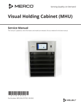
Visual Holding Cabinet (MHC)
Original Instructions
Installation, Operation and Maintenance Manual
This manual is updated as new information and models are released. Visit our website for the latest manual.
Serving Quality on Demand
Part Number: MER_IOM_8197455 10/2018
*8197455*
Original Instructions

Safety Notices
n
Warning
Read this manual thoroughly before operating, installing
or performing maintenance on the equipment. Failure
to follow instructions in this manual can cause property
damage, injury or death.
DANGER
Do not install or operate equipment that has been
misused, abused, neglected, damaged, or altered/
modified from that of original manufactured
specifications.
DANGER
Keep power cord AWAY from HEATED surfaces. DO NOT
immerse power cord or plug in water. DO NOT let power
cord hang over edge of table or counter.
n
Warning
Authorized Service Representatives are obligated to
follow industry standard safety procedures, including,
but not limited to, local/national regulations for
disconnection / lock out / tag out procedures for all
utilities including electric, gas, water and steam.
n
Warning
Do Not Store Or Use Gasoline Or Other Flammable
Vapors Or Liquids In The Vicinity Of This Or Any Other
Appliance. Never use flammable oil soaked cloths or
combustible cleaning solutions, for cleaning.
n
Warning
This product contains chemicals known to the State
of California to cause cancer and/or birth defects or
other reproductive harm. Operation, installation, and
servicing of this product could expose you to airborne
particles of glasswool or ceramic fibers, crystalline
silica, and/or carbon monoxide. Inhalation of airborne
particles of glasswool or ceramic fibers is known to the
State of California to cause cancer. Inhalation of carbon
monoxide is known to the State of California to cause
birth defects or other reproductive harm.
n
Warning
Do not use electrical appliances or accessories other
than those supplied by the manufacturer.
n
Warning
Use caution when handling metal surface edges of all
equipment.
n
Warning
This appliance is not intended for use by children
under the age of 16 or persons with reduced physical,
sensory or mental capabilities, or lack of experience and
knowledge, unless they have been given supervision
concerning use of the appliance by a person responsible
for their safety. Do not allow children to play with this
appliance.
n
Warning
DO NOT use this product near water – for example, near
a kitchen sink, in a wet basement, near a swimming
pool, or similar locations.
NOTE: Proper installation, care and maintenance are essential
for maximum performance and trouble-free operation of
your equipment. Visit our website www.mercoproducts.com
for manual updates, translations, or contact information for
service agents in your area.

Part Number: MER_IOM_8197455
Section 1
General Information
Model Numbers ...............................................................................................................1-1
Serial Number Information ............................................................................................1-1
Warranty Information .....................................................................................................1-1
Regulatory Certifications ...............................................................................................1-1
Section 2
Installation
Location ...........................................................................................................................2-1
Weight of Equipment ......................................................................................................2-2
Clearance Requirements .................................................................................................2-2
Dimensions ......................................................................................................................2-2
Electrical Service .............................................................................................................2-2
Voltage ...................................................................................................................................................2-2
Rated Voltage, Cycles, Phases, Wattage, Amperages & Power Cord Chart ....................2-2
Section 3
Operation
Power Switch ...................................................................................................................3-2
User Interface ..................................................................................................................3-2
Passwords .............................................................................................................................................. 3-2
Press & Go Screens .............................................................................................................................3-2
Tray Specifications .............................................................................................................................3-3
Menu Screens ......................................................................................................................................3-6
Setting Screens ................................................................................................................................ 3-10
Preferences Screen .......................................................................................................................... 3-10
Date & Time Screen .........................................................................................................................3-11
Language Screen ............................................................................................................................. 3-11
Cabinet Names Screen .................................................................................................................. 3-12
Networking Screens ....................................................................................................................... 3-12
Zone Diagnostics Screens ............................................................................................................ 3-13
Sound & Screen Tests ..................................................................................................................... 3-14
Errors Log Screen .............................................................................................................................3-14
Password Settings Screen ............................................................................................................ 3-15
System Information Screen ......................................................................................................... 3-15
Utilities Screen .................................................................................................................................. 3-16
Load New Software Via USB ........................................................................................ 3-16
UI board Update .............................................................................................................................. 3-16
I/O board Update ............................................................................................................................ 3-16
Table of Contents

Part Number: MER_IOM_8197455
Table of Contents (continued)
Section 4
Maintenance
Cleaning and Sanitizing Procedures .............................................................................. 4-1
General ...................................................................................................................................................4-1
Exterior Cleaning ................................................................................................................................4-1
Interior Cleaning ................................................................................................................................. 4-2
Plastic Tray Cleaning ..........................................................................................................................4-2
Daily Cleaning Instructions .............................................................................................................4-2
Section 5
Troubleshooting
Troubleshooting Chart ...................................................................................................5-1

Part Number: MER_IOM_8197455 1-1
Model Numbers
Models Description
MHC22SNT1T 2x2 - Front Display
MHC22SNL1T 2x2 - Front Display Landscape
MHC24SNT2T 2x4 - Front and Rear Display
MHC52SNT1T 5x2 - Front Display
MHC54SNT1T 5x4 - Front Displays
Serial Number Information
MHC visual holding cabinet serial and model numbers are
located on the data plate. The data plate is located on the
top right rear of the unit.
Always have the serial number of your unit available
when calling for parts or service.
Service Personnel
All service on Merco equipment must be performed by
qualified, certified, licensed, and/or authorized or service
personnel.
Qualified service personnel are those who are familiar
with Merco equipment and who have been authorized by
Merco to perform service on the equipment. All authorized
service personnel are required to be equipped with a
complete set of service and parts manuals, and to stock a
minimum amount of parts for Merco equipment. A list
of Merco Factory Authorized Servicers (FAS’s) is located
on the Merco website at http://www.mercoproducts.
com/Service#Service. Failure to use qualified service
personnel will void the Merco warranty on your equipment.
Warranty Information
Visit http://www.mercoproducts.com/Service#Warranty to:
• Register your product for warranty.
• Verify warranty information.
• View and download a copy of your warranty.
Regulatory Certifications
Models are certified by:
• Underwriters Laboratories Sanitation
• Underwriters Laboratories (UL)
• Underwriters Laboratories of Canada (CUL)
FCC Information
This equipment has been tested and found to comply
with the limits for a Class B digital device, pursuant to Part
15 of the FCC Rules. These limits are designed to provide
reasonable protection against harmful interference in a
residential installation. This equipment generates uses and
can radiate radio frequency energy and, if not installed
and used in accordance with the instructions, may cause
harmful interference to radio communications. Howev¬er,
there is no guarantee that interference will not occur in a
particular installation. If this equipment does cause harmful
interference to radio or television reception, which can be
determined by turning the equipment off and on, the user
is encouraged to try to correct the interference by one of
the following measures:
• Reorient or relocate the receiving antenna.
• Increase the separation between the equipment and
receiver.
• Connect the equipment into an outlet on a circuit
different from that to which the receiver is connected.
• Consult the dealer or an experienced radio/TV
technician for help.
Changes or modifications not expressly approved by the
party responsible for compliance could void the user’s
authority to operate the equipment.
This device complies with part 15 of the FCC Rules.
Operation is subject to the following two conditions: (1)
This device may not cause harmful interference, and (2) this
device must accept any interference received, including
interference that may cause undesired operation.
This device complies with Industry Canada’s license-exempt
RSSs. Operation is subject to the following two conditions:
(1) This device may not cause interference; and
(2) This device must accept any interference, including
interference that may cause undesired operation of the
device.
Le présent appareil est conforme aux CNR d’Industrie
Canada applicables aux appareils radio exempts de licence.
L’exploitation est autorisée aux deux conditions suivantes :
1) l’appareil ne doit pas produire de brouillage;
2) l’appareil doit accepter tout brouillage radioélectrique
subi, même si le brouillage est susceptible d’en
compromettre le fonctionnement.
In order to comply with FCC/ISED RF Exposure
requirements, this device must be installed to provide at
Section 1
General Information

1-2 Part Number: MER_IOM_8197455
General Information Section 1
least 5mm separation from the human body at all times.
Afin de se conformer aux exigences d’exposition RF FCC /
ISED, cet appareil doit être installé pour fournir au moins
5mm de séparation du corps humain en tout temps.
The FCC ID numbers:
Reader Board:
FCC ID: 2AQ4D-RFIDREADER
IC: 24291-RFIDREADER
Wi-Fi:
VVXLM808-0407
CAN ICES-3 (B)/NMB-3(B)

Part Number: MER_IOM_8197455 2-1
DANGER
Installation must comply with all applicable fire and
health codes in your jurisdiction.
DANGER
Carts must be installed and the carts must be screwed
in completely.
DANGER
Use appropriate safety equipment during installation
and servicing.
n
Warning
Only trained and authorized service personnel or store
manager should access the service screens. If changes
to these settings are made incorrectly they will cause
the unit to malfunction.
Location
n
Warning
This equipment must be positioned so that the plug is
accessible unless other means for disconnection from
the power supply (e.g., circuit breaker or disconnect
switch) is provided.
n
Warning
Adequate means must be provided to limit the
movement of this appliance without depending on or
transmitting stress to the electrical conduit.
n
Warning
To avoid instability the installation area must be capable
of supporting the combined weight of the equipment
and product. Additionally the equipment must be level
side to side and front to back.
n
Warning
This equipment is intended for indoor use only. Do not
install or operate this equipment in outdoor areas.
The location selected for the equipment must meet the
following criteria. If any of these criteria are not met, select
another location.
• Holding cabinets are intended for indoor use only.
• The location MUST be level, stable and capable of
supporting the weight of the equipment.
• The location MUST be free from and clear of
combustible materials.
• Equipment MUST be level both front to back and side to
side.
• Position the equipment so it will not tip or slide.
• Recommended air temperature is 41° - 86°F (5° - 30°C) .
Section 2
Installation

2-2 Part Number: MER_IOM_8197455
Installation Section 2
RATED VOLTAGES, CYCLES, PHASES, WATTAGE, AMPERAGES & POWER CORD CHART
Units with plugs are supplied with approximately 9ft cords, maximum 10ft.
Domestic Model Voltage, Cycle, Phase Watts Amps Plug
MHC22SNT1T 120V, 60H, 1Ph 660 5.5 5-15P
MHC22SNL1T 120V, 60H, 1Ph 660 5.5 5-15P
MHC24SNT2T 120V, 60H, 1Ph 1320 11.0 5-15P
MHC52SNT1T 120V, 60H, 1Ph 1920 16.0 5-20P
MHC54SNT1T 120V, 60H, 1Ph 2880 24.0 L5-30P
Weight of Equipment
Domestic Model Weight
MHC22SNT1T 38lbs (17kg)
MHC22SNL1T 38lbs (17kg)
MHC24SNT2T 64lbs (29kg)
MHC52SNT1T 147lbs (67kg)
MHC54SNT1T 245lbs (111kg)
Clearance Requirements
DANGER
Minimum clearance requirements are the same for
noncombustible locations as for combustible locations.
The flooring under the appliance must be made of a
noncombustible material.
DANGER
Risk of fire/shock. All minimum clearances must be
maintained. Do not obstruct vents or openings.
Sides/Back
1.0” (25mm)
Dimensions
Domestic Model Width Depth Height
MHC22SNT1T
20.70”
(52.58cm)
12.10”
(30.73cm)
11.50”
(29.21cm)
MHC22SNL1T
15.60”
(39.62cm)
12.10”
(30.73cm)
15.40”
(39.12cm)
MHC24SNT2T
37.50”
(95.25cm)
12.10”
(30.73cm)
11.50”
(29.21cm)
MHC52SNT1T
20.70”
(52.58cm)
22.30”
(56.64cm)
21.80”
(55.37cm)
MHC54SNT1T
32.80”
(83.31cm)
22.40”
(56.89cm)
27.50”
(69.85cm)
Electrical Service
DANGER
Check all wiring connections, including factory
terminals, before operation. Connections can become
loose during shipment and installation.
DANGER
Copper wire suitable for at least 167°F (75°C) must be
used for power connections.
n
Warning
This appliance must be grounded and all field wiring
must conform to all applicable local and national
codes. Refer to rating plate for proper voltage. It is the
responsibility of the end user to provide the disconnect
means to satisfy the authority having jurisdiction.
VOLTAGE
All electrical work, including wire routing and grounding,
must conform to local, state and national electrical codes.
The following precautions must be observed:
• The equipment must be grounded.
• A separate fuse/circuit breaker must be provided for
each unit.
• A qualified electrician must determine proper wire size
dependent upon location, materials used and length
of run (minimum circuit ampacity can be used to help
select the wire size).
• The maximum allowable voltage variation is ±10% of
the rated voltage at equipment start-up (when the
electrical load is highest).
• Check all green ground screws, cables and wire
connections to verify they are tight before start-up.

Part Number: MER_IOM_8197455 3-1
DANGER
The on-site supervisor is responsible for ensuring that
operators are made aware of the inherent dangers of
operating this equipment.
DANGER
Do not operate any appliance with a damaged cord
or plug. All repairs must be performed by a qualified
service company.
DANGER
Never stand on the unit! They are not designed to
hold the weight of an adult, and may collapse or tip if
misused in this manner.
n
Warning
Do not contact moving parts.
n
Warning
All covers and access panels must be in place and
properly secured, before operating this equipment.
n
Warning
Do not put heat sealed containers or plastic bags in
holding cabinet. Food or liquid could expand quickly
and cause container or bag to break. Pierce or open
container or bag before heating.
n
Warning
Racks, utensils, rack guides, and holding cabinet surfaces
may become hot during or after use. Use utensils or
protective clothing, like pan grips or dry oven mitts,
when necessary to avoid burns.
n
Warning
DO NOT use the cavity for storage. DO NOT leave paper
products, cooking utensils, or food in the cavity when
not in use.
,
Caution
DO NOT cover racks or any other part of the holding
cabinet with metal foil.
The Merco Visual Holding Cabinet has been designed to
afford food service operators the ability to cook menu
components in advance and then gently store that product
in the holding bins until an order is received. Once that
order has been placed, the crew can assemble the order
using hot and fresh menu components from the holding
bins. This allows for operators to serve to order, helping
increase speed of service while maintaining high product
quality standards.
Power Switch
The power switch is located on the front of the cabinet. Flip
the power switch to turn the unit on or off.
Power Switch on Front
Section 3
Operation

3-2 Part Number: MER_IOM_8197455
Operation Section 3
User Interface
PASSWORD
• A user can access all necessary screens for daily
operation without a password.
• The factory default manager password is 2580.
PRESS & GO SCREENS
When the unit is turned on zone pre-heating will begin. The
press and go screen will be displayed.
Press & Go Screen Pre-Heating
The unit will beep signaling that all holding zones are pre-
heated and ready for use.
Press & Go Screen
Each product tray must be wrapped with the correct
identification band. As the trays are loaded and recognized
they will be highlighted in green and the product timer will
start.
Press & Go Screen with Active Timers

Part Number: MER_IOM_8197455 3-3
Section 3 Operation
The green portion of the tray timer represents the
remaining time. Each menu item has a programmed
warning time. When the warning time is reached the
elapsed time will fill in with yellow and the alarm will beep.
YellowGreen
Top Left Zone (#9) Reaches the Warning Time
Each menu item has a programmed hold time. When the
times runs out the corresponding tray timer will turn red
and the alarm will beep.
Red
Top Left Zone (#9) Runs out of Hold Time
The alarm will beep for 10 seconds. The timer will display
time the product is being held past programmed hold time.
Tray and food should be removed. Reset the expired tray
timer by selecting it.
Red
Top Left Zone (#9) Runs Over Hold Time
As the trays are removed and returned to the same cabinet
or between communicating holding cabinets, they will be
detected. Their timer will continue whether they are sitting
on the counter or traveling between hot holding cabinets.
When necessary select a tray timer to reset it before the
hold time has expired. The question Reset? will pop up
Select the green check to reset. Select the red X to resume.
Reset Pop Up

3-4 Part Number: MER_IOM_8197455
Operation Section 3
TRAY SPECIFICATIONS
Use First For Identical Products
When two identical products are active, the one with the
least time remaining will be highlighted in green, the others
in gray. There is no change is countdown or timer behavior.
When the first item is canceled or reset, the next one in
order will turn green.
Green
Use Highlighted Tray First
Lid Requirements
• No line above the product name means no lid.
• A dashed line above the product name represents a
vented lid.
• A solid line above the product represents a solid lid.
False Bottom Requirements
• No line below the product name means no false bottom
or a trivet is in the tray.
• A dashed line below the product name means to use a
false bottom.
A Group in the Menu
A product in the menu is part of a group if there are dots
underneath it or arrow heads on either side of it. Select the
menu item with the dots and the other items in the group
will pop up and can be selected. Swipe a product with
arrow heads to choose another item from the group.
Press & Go Screen Icons
On the press and go screen are five icons:
• Home
• Day part
• Lock
• WiFi
• Easy touch logo
Press & Go Screen Five Icons
Select the home icon to bring up the home screen.
Home Icon
Home Screen
From the home menu selecting the press & go icon to
return to the press and go screen.
Press & Go Icon

Part Number: MER_IOM_8197455 3-5
Section 3 Operation
Press & Go Screen
Touch the daypart selection icon to choose a different
menu. The menu options will pop up.
Daypart Selection Icon
Menu Pop Up
Active timers are carried over into the new menu. Once
the item is reset the new product will show up. Waiting
is displayed when the menu changes and the zone
temperature is changing but there is still an active timer
in the zone at the old temperature. The shelf is waiting to
warm up to the new temperature until all active timers at
the old temperature are cleared.
New Menu with
Active Timers from Last Menu Highlighted
On press and go screen the lock icon disables the touch
screen for 10 seconds. The lock icon must be held for 1
second to disable the screen. In the center of the lock
graphic the 10 seconds will be counted down. Ten seconds
of disabled screen allows time for the touch screen to be
cleaned.
Lock Icon
Press & Go Screen Locked for Screen Cleaning
The Wi-Fi Icon indicates the Wi-Fi and local network status
of the machine and others in the kitchen.
Wi-Fi Icon
A zero with a line through it indicates the unit is not
connected to the Wi-Fi.
A one means the unit is connected to Wi-Fi and the local
area network and that it is the only MHC unit connected to
that network.
Numbers two and higher indicate the quantity of units that
are connected to Wi-Fi and that local area network.

3-6 Part Number: MER_IOM_8197455
Operation Section 3
MENU SCREENS
From the home screen selecting the menu icon brings up
the menu screen. The menu screen lists the products saved
in the hot holding unit. 100 products can be saved.
To make changes on the three menu pages a passcode
must be entered. Select the lock on the bottom left of the
screen. Enter a passcode on the pop-up number pad. If the
passcode is accepted the lock icon will appear unlocked. To
return to the home screen select the back arrow.
Menu Icon
Zone Splits: 2
Menu Screen
If the pages are unlocked, the delete, edit and add icons will
display on the menu screen.
Unlocked, Delete, Edit & Add Icons
Select the unwanted product and then the delete icon, X. A
confirmation widow will pop up. Select the green check to
delete the product. Select the red X to return to the menu
screen.
Delete Product Confirmation Window
When a product is edited or added, required specifications
include:
• Name:
• Hold Temp: tray temperature maintained ±5°F
• Product temp: reference only, not measured
• Hold time: maximum time product can be held & served
• Warning time: alarm will sound when the tray has this
length of time remaining. The elapsed time on the timer
bar changes color from white to yellow
• Zone Splits: 2 represents a full size pan (full zone),
1 represents a 1/3 size pan (half zone)
• Lid type: None, Solid or Vented
• Bottom type: Normal or False
Save the edit or product addition by selecting the check.
Select the x to cancel edits and return to product list.
Zone Splits:
2
Product Edit or Addition Screen

Part Number: MER_IOM_8197455 3-7
Section 3 Operation
On the menu screen are navigation icons.
• The first icon returns you to the product list screen.
• The second takes you to the group list screen .
• The third takes you to the day part edit screen.
• To return to the home screen select the back arrow.
Menu, Group, Day Part & Home Navigation Icons
Groups of products can be defined. The products must
have the same lid type, zone split and hold temp. Hold
time, warning time and product temp and can vary within
a group.
From the menu screen, select the group icon. The group
page lists programmed groups. For the highlighted group,
group ID, group name, hold temperature, zone split, lid type
and products included in the group are listed.
Group Icon
Zone Splits: 2
Group Screen
If the group page is unlocked, the delete, edit and add icons
will display on the group screen.
Unlocked, Delete, Edit & Add Icons
Select the unwanted group and then the delete icon, X. A
confirmation widow will pop up. Select the green check to
delete the group. Select the red X to return to the group
screen.
Delete Group Confirmation Window

3-8 Part Number: MER_IOM_8197455
Operation Section 3
Select the group to be edited and the edit icon, a pencil. In
the pop up window the group will appear. You can edit the
group name and add or remove products.
Click inside the name box and a keyboard will appear. When
the group name is edited select the return key (bottom
right).
Pop Up Keyboard
Under the name are the group specifications. Only products
that match will be highlighted and available for adding.
• Select a new product for the group and the green arrow
to add it.
• Select an existing product in the group and the red
arrow to remove it.
• To select the default product for the group (product to
be displayed when the daypart is selected), hold your
finger on that product for three seconds.
• While the unit is in the Press & Go mode the names can
be scrolled from left to right in the same order as they
are listed in the group top to bottom. Delete products
and add them back in to create the desired order.
When the edits are compete return to the group screen by
selecting the X in the top left corner.
Zone Splits: 1
To add a group, select the group page add icon, +. A pop up
window will appear. Click inside the name box and use the
keyboard to enter the group name. Select the return key
(bottom right) and the keyboard will close.
NOTE: Name groups so they are recognizable as groups,
perhaps starting with G or Group. When editing the day
parts to add the group, the name is all that is displayed in
the scrolling list. If it does not stand out as a group it will
appear as just another product.
Pop Up Keyboard
Select a product for the group and the green arrow to add
it. That first product will determine the group specifications,
listed under the group name. Going forward product with
the wrong specifications, not available to be added to the
group, will be grayed out. Continue to add products to the
group. To remove a product, select it and the red arrow.
When the group is complete save it and return to the group
screen by selecting the X in the top left corner.
Zone Splits: 1

Part Number: MER_IOM_8197455 3-9
Section 3 Operation
On the menu screen are navigation icons. Next to the back
arrow is the day part edit icon.
Day Part Edit Icon
Select the day part edit icon and the breakfast products
appears first. Swipe the screen to move between breakfast
and lunch/dinner.
Breakfast Products
To delete a product from a zone hold your finger on the
product for three seconds. A pop-up window confirms the
request to delete.
Select a hot holding zone to add a product or change the
product. From the pop up window select the product you
want to add to the zone. Groups can also be added. Zone
split and zone temperatures will eliminate certain products.
Products not available will be grayed out. Select the green
check to save and return.
Zone Splits: 2
Selecting A Product For Breakfast Zone 3
SETTING SCREENS
From the home screen selecting the settings icon brings
up the preferences screen. This is the first of eleven setting
screens. There are eleven solid dots across the bottom of
the service screens, the empty circle represents the current
page. Touch the dots to bring up a menu. Select and
navigate to a specific screen from the menu. Or navigate
between the screens by swiping the screen to the right or
left.
Settings Icon
Preferences Screen With Row of Dots
Settings Screens Menu

3-10 Part Number: MER_IOM_8197455
Operation Section 3
PREFERENCES SCREEN
To make changes on the preferences screen a passcode
must be entered. Select the lock on the bottom left of the
screen. Enter a passcode on the pop-up number pad. If the
passcode is accepted there will be a yellow ring around the
screen.
Preferences Screen
• Select the green check to implement changes, red cross
to discard.
• Use First – When checked the first tray of common
product will be highlighted in green, second tray will
be gray until the first tray is gone or time runs out.
Unchecked, both trays of the common product will be
green.
• Group Dots - When checked the number of dots indicate
the number of products in that group. The empty circle
indicates the position of the current product. Select
different products by swiping the screen right or left.
• Split View - When checked displays both items when a
group has only two items, the display is split in half. It
is not necessary to swipe between the two items. The
screen space to select the item has been halved, be
careful to choose the desired item. Unchecked the two
item group will display like other groups.
• Individual Day-Parts - This feature is only applicable to
the MHC 5x4 unit. It allows each display and associated
holding zones to be switched from breakfast to lunch/
dinner independently. If unchecked switching day-parts
in the press & go screen from either display will switch
the entire holding cabinet
• Font size can be adjusted between 24-48.
• Volume can be adjusted between 10-100.
DATE & TIME SCREEN
To make changes on the this screen a passcode must be
entered. Select the lock on the bottom left of the screen.
Enter a passcode on the pop-up number pad. If the
passcode is accepted there will be a yellow ring around the
screen.
Date & Time Screen
• If the NTP box is checked and the MHC unit is connected
to the internet via the local WiFi, the date and time
will be set automatically. Be sure to set the UTC to the
appropriate setting (i.e. Eastern Standard time is UTC
-5:00, Central Time is UTC -6:00).
If the MHC unit is not connected to the internet or if the
NTP box is unchecked the time and date will need to be
set manually.
• Top right of the screen provides the choice between a
24hr/military and AM/PM civilian time display.
• Select the month and year by the arrow heads and the
date via the calendar.
• If the DST enabled box is checked the time on the clock
will be moved ahead by 1 hour. If the box is checked
and then unchecked the time on the clock will move
back one hour. Proper use of this feature is to check
the box on the first day of daylight savings time and
uncheck the box on the day after daylight savings time
ends.
• Time Zone - Use the drop down box to select the time
zone the equipment is being used in. This only has an
effect on the date and time setting if the Use NTP box is
checked.

Part Number: MER_IOM_8197455 3-11
Section 3 Operation
LANGUAGE SCREEN
To make changes on the this screen a passcode must be
entered. Select the lock on the bottom left of the screen.
Enter a passcode on the pop-up number pad. If the
passcode is accepted there will be a yellow ring around the
screen.
Language Screen
Available languages are listed to choose from. Store or
company created menu items will not change to the new
language. Only the headings and descriptions will change
to the new language (i.e. service page titles, calendar
month names, product parameters, and menu page titles).
CABINET NAMES SCREEN
To make changes on the this screen a passcode must be
entered. Select the lock on the bottom left of the screen.
Enter a passcode on the pop-up number pad. If the
passcode is accepted there will be a yellow ring around the
screen.
Choices for cabinet name are Reserve Cabinet and Point-
of-Use Cabinet. Cabinet Index is a choice of numbers one
through ten. Scroll left or right to make selections.
Cabinet Names Screen
All cabinets that are connected to the local WiFi and talking
to the other cabinets will be listed in the box. If there are
no other cabinets on the local network and this cabinet is
connected to the WiFi only this cabinet will be in the list.

3-12 Part Number: MER_IOM_8197455
Operation Section 3
NETWORKING SCREENS
To make changes on the this screen a passcode must be
entered. Select the lock on the bottom left of the screen.
Enter a passcode on the pop-up number pad. If the
passcode is accepted there will be a yellow ring around the
screen.
Ethernet Network Screen
Ethernet connectivity is for firmware development
purposes and is not available to the typical user. The Enable
box should always be UN-Checked. Having the Ethernet
Enable box checked can create WiFi connectivity problems.
Wi-Fi Network Screen
To connect the Holding Cabinet to the local WiFi check
both the Enable box and the DHCP box, then touch the box
just to the right of SSID. That will open a new window that
will allow you to enter the name and password of the WiFi
network you would like the holding cabinet to connect to.
See screen shot below.
Wi-Fi Pop-up For Scanning
Touching the scan button will display a list of all WiFi SSIDs
as well as their signal strength, that the cabinet is aware
of. Touching the SSID box will bring up an alphanumeric
keyboard with which you can enter the SSID of the WiFi
network you wish to connect to. Touch the return button
to return to the WiFi Pop-up For Scanning screen. Touch
the Password box to enter the network password (special
characters can be found on the 1# keyboard. Once on the
1# keyboard, more special characters can be found by
touching the up-arrow key.
When finished entering SSID and Password touch the green
check button to save your entries. Touch the green check
button to connect to the WiFi network. Once connected
the fields IP Address, Netmask, and Default Gateway will
be populated, if these fields are not populated the holding
cabinet is not connected to the WiFi network.
/