Page is loading ...

Forced Air Holding Cabinet (MHB)
Original Instructions
Installation, Operation and Maintenance Manual
This manual is updated as new information and models are released. Visit our website for the latest manual.
Part Number: MER_IOM_8197385 03/2017
*8197385*
Original Instructions

Safety Notices
n
Warning
Read this manual thoroughly before operating, installing
or performing maintenance on the equipment. Failure
to follow instructions in this manual can cause property
damage, injury or death.
DANGER
Do not install or operate equipment that has been
misused, abused, neglected, damaged, or altered/
modified from that of original manufactured
specifications.
DANGER
Keep power cord AWAY from HEATED surfaces. DO NOT
immerse power cord or plug in water. DO NOT let power
cord hang over edge of table or counter.
n
Warning
Authorized Service Representatives are obligated to
follow industry standard safety procedures, including,
but not limited to, local/national regulations for
disconnection / lock out / tag out procedures for all
utilities including electric, gas, water and steam.
n
Warning
Do Not Store Or Use Gasoline Or Other Flammable
Vapors Or Liquids In The Vicinity Of This Or Any Other
Appliance. Never use flammable oil soaked cloths or
combustible cleaning solutions, for cleaning.
n
Warning
This product contains chemicals known to the State
of California to cause cancer and/or birth defects or
other reproductive harm. Operation, installation, and
servicing of this product could expose you to airborne
particles of glasswool or ceramic fibers, crystalline
silica, and/or carbon monoxide. Inhalation of airborne
particles of glasswool or ceramic fibers is known to the
State of California to cause cancer. Inhalation of carbon
monoxide is known to the State of California to cause
birth defects or other reproductive harm.
n
Warning
Do not use electrical appliances or accessories other
than those supplied by the manufacturer.
n
Warning
Use caution when handling metal surface edges of all
equipment.
n
Warning
This appliance is not intended for use by children
under the age of 16 or persons with reduced physical,
sensory or mental capabilities, or lack of experience and
knowledge, unless they have been given supervision
concerning use of the appliance by a person responsible
for their safety. Do not allow children to play with this
appliance.
n
Warning
DO NOT use this product near water – for example, near
a kitchen sink, in a wet basement, near a swimming
pool, or similar locations.
NOTE: Proper installation, care and maintenance are essential
for maximum performance and trouble-free operation of
your equipment. Visit our website www.mercoproducts.com
for manual updates, translations, or contact information for
service agents in your area.

Part Number: MER_IOM_8197385
Section 1
General Information
Model Numbers ...............................................................................................................1-1
Serial Number Information ............................................................................................1-1
Service Personnel ............................................................................................................1-1
Shipping Damage Claim Procedure ...............................................................................1-1
Kitchen Management Contact Information ..................................................................1-1
Warranty Information .....................................................................................................1-1
Regulatory Certifications ...............................................................................................1-1
Section 2
Installation
Location ...........................................................................................................................2-1
Weight of Equipment ......................................................................................................2-2
Clearance Requirements .................................................................................................2-2
Dimensions ......................................................................................................................2-2
Electrical Service .............................................................................................................2-3
Voltage, Watts, Rated Amperages & Power Cord Chart ........................................................2-3
Section 3
Operation
Component Identification ..............................................................................................3-1
Control Zones ..................................................................................................................3-2
Control Panel ...................................................................................................................3-2
Controls/Programming/Settings ...................................................................................3-2
Typical Operator Actions .................................................................................................................3-2
Pre-Heat Mode ....................................................................................................................................3-3
Active Heating Mode ........................................................................................................................3-3
Time Button .........................................................................................................................................3-3
Temperature View Mode ................................................................................................................3-3
Changing the Day Part .....................................................................................................................3-3
Timer Bars .............................................................................................................................................3-3
LED Indicators ..................................................................................................................................... 3-4
Section 4
Maintenance
Cleaning and Sanitizing Procedures ..............................................................................4-1
General ...................................................................................................................................................4-1
Exterior Cleaning ................................................................................................................................4-1
Interior Cleaning ................................................................................................................................. 4-2
Plastic Tray Cleaning ..........................................................................................................................4-2
Daily Cleaning Instructions .............................................................................................................4-2
Section 5
Troubleshooting
Troubleshooting Chart ...................................................................................................5-1
Communication Error Messages ....................................................................................5-1
Heater/Thermocouple Error Messages ..........................................................................5-2
Appendices
Installing on a Kitchen Minder Network....................................................................... A-1
Table of Contents

Part Number: MER_IOM_8197385 1-1
Model Numbers
Domestic Models
MHB22SAB1E, 23, 24, 34
MHB22SAR2E, 23, 24, 34
MHB22SAB2E, 23, 24, 34
Understanding Model Numbers
M H B 2 2 S A B 2 E
Merco
Hot Holding
Cabinet
Customer
Rows
Columns
(Trays per
shelf)
Lower Heat
Upper Heat
Display
Control Faces
Connectivity
B- Burger King
1-5
1-4
S- Standard
A- Forced Air
B-Timer Bar
R-Timer Ready
1- One Side
2- Two Sided
E- Ethernet
Serial Number Information
MHB holding cabinet serial and model numbers are located
on the data plate. Data plates are located on the bottom and
the right end of the unit.
Always have the serial number of your unit available
when calling for parts or service.
Service Personnel
All service on Merco equipment must be performed by
qualified, certified, licensed, and/or authorized or service
personnel.
Qualified service personnel are those who are familiar with
Merco equipment and who have been authorized by Merco
to perform service on the equipment. All authorized service
personnel are required to be equipped with a complete
set of service and parts manuals, and to stock a minimum
amount of parts for Merco equipment. A list of Merco Factory
Authorized Servicers (FAS’s) is located on the Merco website
at http://www.mercoproducts.com/Service#Service. Failure
to use qualified service personnel will void the Merco
warranty on your equipment.
Shipping Damage Claim Procedure
What to do if your equipment arrives damaged:
Please note that this equipment was carefully inspected
and packed by skilled personnel before leaving the factory.
The freight company assumes full responsibility for safe
delivery upon acceptance of the equipment.
1. File Claim for Damages Immediately - regardless of
extent of damage.
2. Inspect For and Record All Visible Loss or Damage,
and ensure that this information is noted on the freight
bill or express receipt and is signed by the person
making the delivery.
3. Concealed Loss or Damage- If damage is unnoticed until
equipment is unpacked, notify the freight company or
carrier immediately upon discovery and file a concealed
damage claim. This must be submitted within 15 days of
date of delivery. Be sure to retain container for inspection.
MERCO DOES NOT ASSUME RESPONSIBILITY FOR DAMAGE
OR LOSS INCURRED IN TRANSIT.
Kitchen Management Contact Information
For Kitchen Minder connection questions and issues call
- ICC Tech Division 631-673-5100 or 877-422-8788 (North
America only).
For SICOM Chef Minder connection questions and issues
call - 800-547-4266 (North America only).
Warranty Information
Visit http://www.mercoproducts.com/Service#Warranty to:
• Register your product for warranty.
• Verify warranty information.
• View and download a copy of your warranty.
Regulatory Certifications
Domestic Models are certified by:
• Underwriters Laboratories Sanitation
• Underwriters Laboratories (UL)
• Underwriters Laboratories of Canada (ULC)
Section 1
General Information

Part Number: MER_IOM_8197385 2-1
DANGER
Installation must comply with all applicable fire and
health codes in your jurisdiction.
DANGER
Legs must be installed and the legs must be screwed in
completely.
DANGER
Use appropriate safety equipment during installation
and servicing.
n
Warning
Only trained and authorized service personnel or store
manager should access the service screens. If changes
to these settings are made incorrectly they will cause
the unit to malfunction.
Location
n
Warning
This equipment must be positioned so that the plug is
accessible unless other means for disconnection from
the power supply (e.g., circuit breaker or disconnect
switch) is provided.
n
Warning
Adequate means must be provided to limit the
movement of this appliance without depending on or
transmitting stress to the electrical conduit or gas lines.
n
Warning
To avoid instability the installation area must be capable
of supporting the combined weight of the equipment
and product. Additionally the equipment must be level
side to side and front to back.
n
Warning
This equipment is intended for indoor use only. Do not
install or operate this equipment in outdoor areas.
,
Caution
Do not position the air intake vent near steam or heat
exhaust of another appliance.
The location selected for the equipment must meet the
following criteria. If any of these criteria are not met, select
another location.
• Holding cabinets are intended for indoor use only.
• The location MUST be level, stable and capable of
supporting the weight of the equipment.
• The location MUST be free from and clear of
combustible materials.
• Equipment MUST be level both front to back and side to
side.
• Position the equipment so it will not tip or slide.
• Recommended air temperature is 41° - 86°F (5° - 30°C) .
• Proper air supply for ventilation is REQUIRED AND
CRITICAL for safe and efficient operation. Refer to
Clearance Requirements chart on page 2-2.
• Do not obstruct the flow of ventilation air. Make sure the
air vents of the equipment are not blocked.
Section 2
Installation

2-2 Part Number: MER_IOM_8197385
Installation Section 2
Weight of Equipment
Domestic Model Weight
MHB22 50lbs/23kg
MHB23 65lbs/30kg
MHB24 115lbs/52kg
MHB34 150lbs/68kg
Clearance Requirements
DANGER
Minimum clearance requirements are the same for
noncombustible locations as for combustible locations.
The flooring under the appliance must be made of a
noncombustible material.
DANGER
Risk of fire/shock. All minimum clearances must be
maintained. Do not obstruct vents or openings.
Sides/Back
1.0” (25mm)
Dimensions
Domestic
Model
Width Depth Depth
incl
Timer
Bars
Height
MHB22SAB1E
19.20”
(488mm)
13.00”
(330mm)
15.60”
(396mm)
11.00”
(279mm)
MHB22SAR2E N/A
10.60”
(269mm)
MHB22SAB2E
18.10”
(460mm)
11.00”
(279mm)
MHB23SAB1E
29.70”
(754mm)
15.60”
(396mm)
11.00”
(279mm)
MHB23SAR2E N/A
10.60”
(269mm)
MHB23SAB2E
18.10”
(460mm)
11.00”
(279mm)
MHB24SAB1E
36.50”
(927mm)
15.60”
(396mm)
11.00”
(279mm)
MHB24SAR2E N/A
10.60”
(269mm)
MHB24SAB2E
18.10”
(460mm)
11.00”
(279mm)
MHB34SAB1E
15.60”
(396mm)
15.90”
(404mm)
MHB34SAR2E N/A
15.90”
(404mm)
MHB34SAB2E
18.10”
(460mm)
15.90”
(404mm)

Part Number: MER_IOM_8197385 2-3
Section 2 Installation
Electrical Service
DANGER
Check all wiring connections, including factory
terminals, before operation. Connections can become
loose during shipment and installation.
DANGER
Copper wire suitable for at least 167°F (75°C) must be
used for power connections.
n
Warning
This appliance must be grounded and all field wiring
must conform to all applicable local and national
codes. Refer to rating plate for proper voltage. It is the
responsibility of the end user to provide the disconnect
means to satisfy the authority having jurisdiction.
VOLTAGE, WATTS, RATED AMPERAGES & POWER CORD
CHART
All electrical work, including wire routing and grounding,
must conform to local, state and national electrical codes.
The following precautions must be observed:
• The equipment must be grounded.
• A separate fuse/circuit breaker must be provided for
each unit.
• A qualified electrician must determine proper wire size
dependent upon location, materials used and length of
run (minimum circuit amp capacity can be used to help
select the wire size).
• The maximum allowable voltage variation is ±10% of
the rated voltage at equipment start-up (when the
electrical load is highest).
• Check all green ground screws, cables and wire
connections to verify they are tight before start-up.
Units with plugs are supplied with approximately 9ft cords,
maximum 10ft.
Domestic Model Voltage, Cycle, Phase Watts Amps Plug
MHB22 120, 60, 1 1920 16.0 5-20P
MHB23 208-230, 60, 1 3174 13.8 6-20P
MHB24 208-230, 60, 1 3680 16.0 6-20P
MHB34 208, 60, 1 3120 15.0 6-20P
Connect the power cord ensuring the plug is fully seated in the receptacle.
If connecting to a Kitchen Minder system see Appendix A.
If connecting to a Duke Visor system see Appendix B.
If connecting to a Sicom Chef Minder system see Appendix C.

Part Number: MER_IOM_8197385 3-1
DANGER
The on-site supervisor is responsible for ensuring that
operators are made aware of the inherent dangers of
operating this equipment.
DANGER
Do not operate any appliance with a damaged cord
or plug. All repairs must be performed by a qualified
service company.
DANGER
Never stand on the unit! They are not designed to
hold the weight of an adult, and may collapse or tip if
misused in this manner.
n
Warning
Do not contact moving parts.
n
Warning
All covers and access panels must be in place and
properly secured, before operating this equipment.
n
Warning
Liquids such as water, coffee, or tea can be overheated
beyond the boiling point without appearing to be
boiling due to surface tension of the liquid. Visible
bubbling or boiling when the container is removed from
the microwave oven is not always present. THIS COULD
RESULT IN VERY HOT LIQUIDS SUDDENLY BOILING OVER
WHEN A SPOON OR OTHER UTENSIL IS INSERTED INTO
THE LIQUID. To reduce the risk of injury to persons: Do
not overheat the liquid. Stir the liquid both before and
halfway through heating it.
n
Warning
Do not heat sealed containers or plastic bags in oven.
Food or liquid could expand quickly and cause container
or bag to break. Pierce or open container or bag before
heating.
n
Warning
Racks, utensils, rack guides, and oven surfaces may
become hot during or after use. Use utensils or
protective clothing, like pan grips or dry oven mitts,
when necessary to avoid burns.
n
Warning
DO NOT use the cavity for storage. DO NOT leave paper
products, cooking utensils, or food in the cavity when
not in use.
,
Caution
Do not block the supply and return air grills or the air
space around the air grills. Keep plastic wrappings,
paper, labels, etc. from being airborne and lodging in
the grills. Failure to keep the air grills clear will result in
unsatisfactory operation of the system.
,
Caution
Some products such as whole eggs or sealed containers
– for example, closed glass jars – are able to explode
and SHOULD NOT be HEATED in this oven. Pressure may
build up and erupt. Pierce yolk with fork or knife before
cooking. Pierce skin of potatoes, tomatoes, and similar
foods before cooking with microwave energy. When
skin is pierced, steam escapes evenly.
,
Caution
DO NOT cover racks or any other part of the oven with
metal foil. Airflow restriction will cause overheating of
the oven.
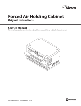
Component Identification
Section 3
Operation
Heated air
from top
Heated
plate from
below
Timer Bar
Control Panel
- Limited use on
units attached
to monitoring
network
Tray Seal
- Diffuser is
above tray
seal

3-2 Part Number: MER_IOM_8197385
Operation Section 3
Control Zones
The rows are divided to zones, which are heated individually.
Two bins will fit in one zone.
The cabinet is designed to operate on a network, which
configures the PHU and monitors food usage. The unit’s
network connection status is shown by an LED (see arrow
above).
LED ON: Unit is managed by network.
LED OFF: Standalone operation; day parts can be changed.
NOTE: In standalone mode, the unit works in a default bin
configuration that can’t be revised with the controller.
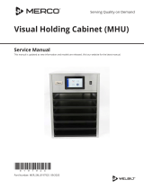
Control Panel
Use the illustration below for the display that matches the
unit.
Controls/Programming/Settings
The Merco Holding Cabinet has been designed to afford
food service operators the ability to cook menu components
in advance and then gently store that product in the holding
bins until an order is received. Once that order has been
placed, the crew can assemble the order using hot and fresh
menu components from the holding bins. This allows for
operators to serve to order, helping increase speed of service
while maintaining high product quality standards.
• The holding cabinet blows heated air down from the
upper platen to the food in the trays.
• Heated air removes moisture from the food surface,
maintaining a crispy exterior and hot and moist interior.
• Airflow passes over the food items and exits through
holes in the tray sidewalls.
• Dual function for grilled and fried food holding
TYPICAL OPERATOR ACTIONS
Action Instructions
Turn Unit On Push Power button.
Load bin with
product
Pull out tray, load product and reinsert
tray.
Empty bin Pull out tray and remove product.
Reinsert tray.
When the unit is first powered ON, it will begin to preheat.
The displays will display PRE-HEAT alternating with the
product name.
The holding cabinet will operate in a stand alone mode or
will be controlled by a kitchen system.
In stand alone mode the holding cabinet will heat up to
the pre-set default temperature. The holding cabinet will
have a default menu and zone assignment. These can not
be adjusted from the cabinet. Adjustment of bin locations,
times and temperatures can be performed from a PC
application.
In stand alone mode only day-parts can be changed. Zones
and temperatures can not be adjusted.
The holding bin controller is, at all times, operating in one of
the following modes. The indents indicate the sub-modes.
Sub-modes are defined based on the navigation to the
mode. I.e., to get to diagnostic mode you must be in active
heating mode then enter programming mode.
• Pre-Heat Mode
• Active Heating Mode
» Diagnostic Mode
- Temperature View Mode
» Diagnostic Temperature View Mode
Zone 1
Zone 2
Zone 3 Zone 4
Time Button
(non-functional)
Temperature
Button
Power
Switch
Program
Button
Connectivity
LED
Day Part
Button
Day Part
LED’s
Enter
Button
Cancel
Button
Down
Button
Up
Button
Time Button
(non-functional)
Temperature
Button
Power
Switch
Program
Button
Connectivity
LED
Day Part
Button
Day Part
LED’s
Enter
Button
Cancel
Button
Down
Button
Up
Button

Section 3 Operation
Part Number: MER_IOM_8197385 3-3
PREHEAT MODE
The displays shall scroll PRE-HEAT alternating with the
product temperature during the pre-heat mode until the
heater reaches set point minus 15°F. The timer bar will display
the product name once the pre-heat mode completes. If a
product is not assigned to the bin, the timer bar will display
“- - - -”. The LED corresponding to the active Day Part menu
configuration will be on.
During Pre-Heat mode, all button presses will be ignored
except the check mark (ENTER) button.
ACTIVE HEATING MODE
This is the active heating mode of operation. In active
heating mode the displays will be blank and the day part
LED light will be ON.
During active heating mode, press and hold enter for three
(3) seconds to scroll the software version on the display.
TIME BUTTON
The displays alternate between the actual hold time and the
product name. Pressing the time button will switch off the
timers and only display the product names.
TEMPERATURE VIEW MODE
Enter the temperature view mode by pressing the
temperature button. The average temperature for each zone
is displayed. Press the cancel button to exit.
CHANGING THE DAY PART
Pressing the Day Part button will change to one of three
day parts for ICC systems and six day parts for Duke/Sicom
in stand alone mode (see matrix for which day part menu
is displayed). Illuminated day part LED indicates the unit is
in stand alone mode. The day part switch is disabled when
controlled by a network.
Default Day Part Menus
Day Part # LED 1 LED 2 LED3
1 (Breakfast)
•
2 (Change Over 1)
• •
3 (Lunch)
•
4 (Change Over 2)
• •
5 (Dinner)
•
6 (Change Over 3)
• •
TIMER BARS
• Two timer bars on a 3-row cabinet.
• Top timer controls the top slots.
• Bottom timers control 2nd and 3rd slots.
• Note arrows at menu names.
LED INDICATORS
The timer bar’s LED’s indicate:
• Trays to pull from first
• When a product is near expiration.
• Product is expired.
• Bin is out of product
See next page for legend.
Top row ▲
2nd row ▲
3rd row ▼

3-4 Part Number: MER_IOM_8197385
Operation Section 3
Use 1
st
, when pan is empty
press the button with the arrow.
Use Green Product 1
st
Near expiration, cook more if needed
Near expiration, cook more if needed
Expired, discard product, press
button with the arrow.
Out of product, pull pan out.
Refer to Kitchen Minder.
Off, no product needed (KM™ only)
GREEN
GREEN
AMBER
AMBER
RED
RED

Part Number: MER_IOM_8197385 4-1
DANGER
All utility connections and fixtures must be maintained
in accordance with local and national codes.
DANGER
It is the responsibility of the equipment owner to
perform a Personal Protective Equipment Hazard
Assessment to ensure adequate protection during
maintenance procedures.
DANGER
Failure to disconnect the power at the main power
supply disconnect could result in serious injury or death.
The power switch DOES NOT disconnect all incoming
power.
DANGER
Always discharge the ht capacitors before working on
the oven using a suitably insulated 10mo resistor.
DANGER
Disconnect electric power at the main power disconnect
for all equipment being serviced. Observe correct
polarity of incoming line voltage. Incorrect polarity can
lead to erratic operation.
n
Warning
When using cleaning fluids or chemicals, rubber gloves
and eye protection (and/or face shield) must be worn.
,
Caution
Maintenance and servicing work other than cleaning as
described in this manual must be done by an authorized
service personnel.
Cleaning and Sanitizing Procedures
GENERAL
You are responsible for maintaining the equipment
in accordance with the instructions in this manual.
Maintenance procedures are not covered by the warranty.
Maintenance Daily After Prolonged
Shutdown
At Start-Up
Exterior X X X
Interior X X X
Tray Seal & Air
Diffuser
X X X
Plastic Tray X X X
EXTERIOR CLEANING
n
Warning
Never use a high-pressure water jet for cleaning or hose
down or flood interior or exterior of units with water. Do
not use power cleaning equipment, steel wool, scrapers
or wire brushes on stainless steel or painted surfaces.
,
Caution
Never use an acid based cleaning solution on exterior
panels! Many food products have an acidic content,
which can deteriorate the finish. Be sure to clean the
stainless steel surfaces of ALL food products.
The stainless steel outer case requires nothing more than
a daily wiping with a damp cloth. If, however, an excessive
amount of food particles/grease are allowed to collect, a
non-abrasive cleaner (hot sudsy water) may be used. Wipe
dry with a clean, soft cloth.
Always rub with the “grain” of the stainless steel to avoid
marring the finish. Never use steel wool or abrasive pads
for cleaning. Never use chlorinated, citrus based or abrasive
cleaners.
Stainless steel exterior panels have a clear coating that
is stain resistant and easy to clean. Products containing
abrasives will damage the coating and scratch the panels.
Daily cleaning may be followed by an application of
stainless steel cleaner which will eliminate water spotting
and fingerprints. Early signs of stainless steel breakdown
are small pits and cracks. If this has begun, clean thoroughly
and start to apply stainless steel cleaners in an attempt to
restore the steel.
Section 4
Maintenance

4-2 Part Number: MER_IOM_8197385
Maintenance Section 4
INTERIOR CLEANING
,
Caution
Do not use caustic cleaners on any part of the oven or
oven cavity . Use mild, non abrasive soaps or detergents,
applied with a sponge or soft cloth. Never use sharp
implements or harsh abrasives on any part of the oven.
The product trays, tray seals and air diffusers may be
cleaned via dishwasher or with warm soapy water. Care
must be taken to prevent water or cleaning compounds
from getting on internal parts, especially the switches on
the control panel.
PLASTIC TRAY CLEANING
,
Caution
Environmental stress cracking can occur. Proper dilution
and rinsing per detergent manufacturers’ directions are
mandatory.
Food-approved detergents can be used if they are diluted
per manufacturers’ directions and adequately rinsed
away prior to high temp drying cycle. Basic alcohols such
as isopropyl are acceptable for hard-to-remove stains.
Otherwise, do not use organic solvents.
DAILY CLEANING INSTRUCTIONS
,
Caution
The unit must be cool to the touch and disconnected
from the power source prior to cleaning, to avoid contact
with hot surfaces which may cause burns or injury. Use
caution and wear appropriate safety equipment to
avoid contact with hot surfaces that may cause severe
burns or injury.
Unit must be cool to touch and disconnected from
power source.
1. Wipe the stainless steel outer case with a damp cloth,
rubbing with the grain of the steel. If an excessive
amount of food particles/grease has collected, hot
sudsy water (non-abrasive) may be used.
2. Remove trays.
,
Caution
Use caution when raising the locking clips to avoid
pinching a finger between the air diffuser assembly and
the back of the timer bar (see illustration below).
3. Raise/lift the locking clips to remove the air diffusers
and/or tray seals.

Part Number: MER_IOM_8197385 4-3
Section 4 Maintenance
4. Remove air diffuser assemblies.
5. The product trays, tray seals and air diffusers may be
cleaned via dishwasher or with warm soapy water.
6. Wipe the interior shelf with a damp cloth. If, however,
an excessive amount of food particles/grease has
collected, hot sudsy water (non-abrasive) may be used
on the cloth.
,
Caution
Use caution when inserting the air diffuser into the
unit to avoid pinching a finger between the air diffuser
assembly and the back of the air plenum assembly on
the rear of the unit (see illustration below).
7. Reinstall cleaned air diffusers and tray seals.
8. Reinstall the cleaned trays.
9. Plug the unit in.

Part Number: MER_IOM_8197385 5-1
Troubleshooting Chart
Problem Cause Correction
Cabinet not
running
Fuse blown or circuit breaker tripped. Replace fuse or reset circuit breaker.
Power cord unplugged. Plug in power cord.
Thermostat set too high. Set thermostat to lower temperature on PC Minder.
Main power switch turned off. Turn main power switch on.
Cabinet
temperature is too
high
Thermostat set too high. Set thermostat to lower temperature on PC Minder.
Poor air circulation in cabinet. Re-arrange product to allow proper air circulation.
Exterior thermometer is out of calibration. Contact FAS
Cabinet
temperature is too
low
Air diffuser out of unit. Reinstall air diffuser.
Product trays out of unit. Reinstall product trays in unit.
Cabinet is not
communicating
with Kitchen
Management
System
Disconnected cables • Ensure all cables are securely connected to the Kitchen
Management system and the PHU’s. Check for defective
or damaged cables.
• Ensure the communication LED on the control panel is
illuminated.
ICC Kitchen
Minder Only
Cabinet is not
communicating
with Kitchen
Minder
A. PWR LED on ICC
translator box is not
illuminated.
B. COMM LED on
ICC translator box
is flashing at 1 sec
interval.
C. COMM LED on
ICC translator box is
flashing bright.
A. Translator box is not attached to Kitchen
Minder.
A. Ensure the cable between the translator box and Kitchen
Minder is connected.
B. Translator box is not connected or
communicating with the primary cabinet.
B. Ensure the cable between the translator box and primary
cabinet is connected.
C. A network communication issue exists. C. Check network cables and ensure they are securely
connected. Check for defective or damaged cables.
COMMUNICATION ERROR MESSAGES
Display Probable Cause Corrective Action
MOD-ERR1 Timer bar lost communication with I/O
board.
Call your FAS.
MOD-ERR2 Master I/O board lost communication
with the slave I/O board.
Call your FAS.
CAN-ERR Communication lost between KCCM
SUI communication board and I/O
board.
Call your FAS.
STANDALONE Communication lost between PHU and
KMS (Kitchen Management System).
Ensure all connections between PHU and KMS (Kitchen
Management System) are secure.
Section 5
Troubleshooting

5-2 Part Number: MER_IOM_8197385
Troubleshooting Section 5
HEATER/THERMOCOUPLE ERROR MESSAGES
Display Probable Cause Corrective Action
ErU1 Upper heater/thermocouple is shorted. Call your FAS.
ErL1 Lower heater/thermocouple is shorted. Call your FAS.
ErU2 Upper heater/thermocouple is open. Call your FAS.
ErL2 Lower heater/thermocouple is open. Call your FAS.
ErU3 Upper heater/thermocouple is below range. Call your FAS.
ErL3 Lower heater/thermocouple is below range. Call your FAS.
ErU4 Upper heater/thermocouple is above range. Call your FAS.
ErL4 Lower heater/thermocouple is above range. Call your FAS.
If any of the error messages below are displayed call your FAS. Turning Off and On a unit will clear all thermocouple error
displays.

Part Number: MER_IOM_8197385 A-1
NOTICE
The Merco holding cabinet is incompatible with older
Kitchen Minder networks and software. Minimum
requirements for operation are:
ICC PC Minder – Version 6.0 or greater
ICC Kitchen Minder – Version 6.01 or greater
Follow the steps below to install the holding unit on a
Kitchen Minder II network with Version 6 software. If the
Kitchen Minder system is not compatible, the holding
cabinet will need to be operated in stand alone mode.
NOTICE
If a Merco holding cabinet is replacing another brand
holding cabinet on the network, store management will
have to reacquire the Merco holding cabinet under its
brand name in the PC Minder software. The menu of the
Merco holding cabinet will also have to be configured
with the PC Minder software.
1. Remove existing holding cabinets.
2. Route new cable if necessary.
3. Position new Merco holding cabinets. (See Store
Network Overview and Component Start Up
Sequence on Page A-2). Be attentive to the placement
of the cabinets that are to be the primary or the
initial unit on a COM port. It will be daisy chained to a
secondary cabinet. The primary cabinet must be larger
or equal in size to the secondary unit. The combined bin
count cannot exceed 24 on a COM Port.
4. Position Merco Translator boxes near the Primary cabinet
on each COM port. A Merco Translator is required for
each COM Port. Translators are not required for Primary
to Secondary cabinet connections.
5. Connect CAT 5 cable to the COM Ports of the Kitchen
Minder (See Figure 1) and route to the Merco translator
for the primary cabinets. Connect the translator to the
primary cabinet with the RJ12 cable.
6. Connect the secondary cabinet (See Figure 2) to the
primary with CAT 5 cable.
7. With all cabinets in place and connected, turn on all
secondary cabinets. (The Secondary cabinet must
be visible to the Primary cabinet during its start up
sequence.). See Network and Start Up Sequence
Graphic on page A-2.
8. Turn on Primary cabinets.
9. Turn on Kitchen Minder.
10. If the Merco holding cabinet is replacing another brand
holding cabinet, store management will have to acquire
the new cabinet from the PC Minder software and select
Merco from the brand pull-down. The cabinet will also
have to be repopulated with menu items.
11. Use the test outlined in the following graphics to ensure
all cabinets are visible on the network. See testing and
Kitchen Minder graphic button mapping diagrams
on pages A3-A5.
Troubleshooting Connection Issues
A healthy communication signal between the Kitchen
Minder and the Merco Translator is indicated by LED’s. The
PWR ON LED should be on solid. There should be a faint
and irregular light on the COMM LED. A solid but regularly
flashing COMM LED indicates a communication issue, which
is often associated with cables or plugs.
Appendix A
Installing Merco PHU’s on a Kitchen Minder Network
Figure 1: COM ports on the back of the Kitchen Minder are
connected to Merco Translators, which are in turn connected
to a Merco holding cabinet.
Figure 2: The translator
connects to the primary
holding cabinet with RJ12
cable (right). The secondary
cabinet, if present, is
connected with CAT 5 cable
(left). The primary cabinet
must be larger or equal in size
to the secondary cabinet.
Figure 3: The PWR LED is illuminated when the network is
active. The COMM LED should only show a weak intermittent
blink, which indicates successful network activity. A bright
flashing COMM LED is indicative of a network communication
issue, often associated with cables. The translator box above
is unplugged from the holding cabinet.

A-2 Part Number: MER_IOM_8197385
Kitchen Minder Installation Appendix A
Store Network Overview and Component Start Up Sequence
This network map of a typical store installation has been annotated, indicating the roles of the components.
Follow this sequence when starting up Merco holding cabinets on a Kitchen Minder network:
1. Start the Secondary holding cabinets.
2. Start the Primary holding cabinets.
3. Start the Kitchen Minder. The Merco Translator’s Power LED will glow solidly when the network is on and the COM LED
will emit a weak blink as data moves on the line.
A CAT 5 cable connects the translator to the first cabinet, or primary, in the series. A RS232 cable connects the translator
to the primary holding cabinet. The CAT 5 is also used to connect the secondary cabinet. The total number of bins on the
Kitchen Minder’s COM port connections cannot exceed 24.
PC Minder: Software running on a store
computer, which is used to populate the
Kitchen Minder menus, etc. The network
must be reconfigured in this software
when a Merco holding cabinet replaces
a holding cabinet of another brand.
The new cabinet will also have to be
populated with products from the PC
minder.
Merco Translator: must be
between the Kitchen Minder
and the new generation
Merco holding cabinets.
Secondary Cabinet:
must be smaller or
equal in size to the
secondary cabinet.
Primary Cabinet:
must be larger or
equal in size to the
secondary cabinet.
Kitchen Minder: Use display
to navigate to Product Locator
and use tray graphics to test the
communication between the
Kitchen Minder and the newly
installed holding cabinets. See
testing and button mapping on
pages A-3- A5.
Start 1st
Start 2nd
Start 3rd

Part Number: MER_IOM_8197385 A-3
Appendix A Kitchen Minder Installation
Testing Merco Holding Cabinet Communication on Network
The letters on the graphic turn red
when pressed. A red LED should light
on the Merco holding cabinet with
the pressing of the pan graphic.
The graphics on the following pages describe how to use the Kitchen Minder interface to ensure the holding cabinets are
communicating on the network. The touchscreen graphics on the Kitchen Minder do not correspond visually to rows on the
holding cabinets. See button mapping graphic on page A-5. Holding cabinets connected to COM port 1 will be shown
in Warmer graphics 1, 2, 3. Holding cabinets connected to COM port 2 will be shown in warmer graphics 4, 5, 6. Holding
cabinets connected to COM port 3 will be shown in Warmer graphic 7, 8 and 9. This means that a configuration of two 3x4
holding cabinets on COM port 1 will be seen on warmer graphics 1, 2 and 3. See COM port 1 graphic on page A-4. Two 3x4’s
on COM port 2 will be seen as Warmer graphics 4, 5 and 6 and a single 2x3 holding cabinet on COM port 3 will be seen on
Warmer graphic 7.
• Press Menu button to display
graphic choices for the Kitchen
Minder.
• Use the arrows under the Select
button to move the cursor to
Product Location.
• Press Select.
• Product Location is displayed.
• Pressing the pan graphics
will illuminate a red LED
on the cabinet, indicating
communication.
NOTE: The position of the pan
graphic doesn’t align with
the position on the cabinet.
The mapping of the Kitchen
Minder buttons to the cabinet
is explained in a graphic and
schematic on pages A-4 - A-5.

A-4 Part Number: MER_IOM_8197385
Kitchen Minder Installation Appendix A
Testing Merco Holding Cabinets/Kitchen Minder Communication
Warmer 1
Press pan graphics on top row of Kitchen Minder Warmer 1 graphic
to illuminate the up buttons on the bottom row of the primary
holding cabinet on COM Port 1.
Press pan graphics on bottom row of Kitchen Minder Warmer 1 graphic to
illuminate the down buttons on the bottom row of the primary holding
cabinet on COM Port 1.
Warmer 2
Press pan graphics on top row of Kitchen Minder Warmer 2 graphic
to illuminate the up buttons on the top row of the primary holding
cabinet on COM Port 1.
Warmer 3
Press pan graphics on bottom row of Kitchen Minder Warmer 2
graphic to illuminate the top row buttons of the secondary holding
cabinet on COM Port 1.
Press pan graphics on top row of Kitchen Minder Warmer 3 graphic
to illuminate the up buttons on the bottom row of the secondary
holding cabinet on COM Port 1.
Press pan graphics on bottom row of Kitchen Minder Warmer 3
graphic to illuminate the down buttons on the bottom row of the
secondary holding cabinet on COM Port 1.
Testing Merco Holding Cabinets
/Kitchen Minder Communication
Follow these steps to ensure all Me
rco Holding Cabinet’s on the Kitchen Minder network are communicating.
1. Navigate to the Product Loca
tor screen of the Kitchen Minder: Press the Menu button and scroll the cursor to the Product Locator with the
up or down arrows.
2. Press the select
button with cursor on the Product Locator.
3. Press the graphics in the numbered warm
er graphics. The text in the graphic will turn red. There should be a corresponding illumination of a
red LED on the same cabinet position. Follow the directions belo
w and see the visual guide to the mapping of the cabinet buttons and the
Kitchen Minder Product Locator.
The example below shows
a primary and secondary cabinet attached to COM Port 1.
Primary Cabinet
Secondary Cabinet
Kitchen Minder Pro
duct Locator Display
COM Port 1
/