Page is loading ...

Concepts Serving Systems
Installation Manual
Please read this manual completely before attempting to install or operate this equipment!
Notify carrier of damage! Inspect all components immediately.
February 2013

Concepts Installation Manual
For customer service, call (800) 733-8829, (800) 773-8821, Fax (989) 773-3210, www.deleld.com
2
WARNING Read This Manual Thoroughly Before Operating, Installing, Or Performing Maintenance On The Equipment.
WARNING Failure To Follow Instructions In This Manual Can Cause Property Damage, Injury Or Death.
WARNING Do Not Store Or Use Gasoline Or Other Flammable Vapors Or Liquids In The Vicinity Of This Or Any Other
Appliance.
WARNING Unless All Cover And Access Panels Are In Place And Properly Secured, Do Not Operate This Equipment.
WARNING This Appliance Is Not Intended For Use By Persons Who Lack Experience Or Knowledge, Unless They Have
Been Given Supervision Or Instruction Concerning Use Of The Appliance By A Person Responsible For Their
Safety.
WARNING This Appliance Is Not To Be Played With.
WARNING Do Not Clean With Water Jet.
WARNING Do Not Use Electrical Appliances Inside The Food Storage Compartment Of This Appliance.
CAUTION Observe the following:
• Minimum clearances must be maintained from all walls and combustible materials.
• Keep the equipment area free and clear of combustible material.
• Allow adequate clearance for air openings.
• Operate equipment only on the type of electricity indicated on the specification plate.
• Unplug the unit before making any repairs.
• Retain this manual for future reference.
Important Warning And Safety Information

Concepts Installation Manual
3
For customer service, call (800) 733-8829, (800) 773-8821, Fax (989) 773-3210, www.deleld.com
Contents
Receiving And Inspecting The Equipment
Even though most equipment is shipped crated, care should be
taken during unloading so the equipment is not damaged while
being moved into the building.
1. Visually inspect the exterior of the package and skid or
container. Any damage should be noted and reported to
the delivering carrier immediately.
2. If damaged, open and inspect the contents with the carrier.
3. In the event that the exterior is not damaged, yet upon
opening, there is concealed damage to the equipment
notify the carrier. Notification should be made verbally as
well as in written form.
4. Request an inspection by the shipping company of the
damaged equipment. This should be done within 10 days
from receipt of the equipment.
5. Check the lower portion of the unit to be sure legs or
casters are not bent.
6. Also open the compressor compartment housing and
visually inspect the refrigeration package. Be sure lines
are secure and base is still intact.
7. Freight carriers can supply the necessary damage forms
upon request.
8. Retain all crating material until an inspection has been
made or waived.
The units with LiquiTec technology cold pans contain
a non-toxic eutectic fluid within a sealed inner liner.
This fluid may leak if the tank is punctured so care
must be taken when uncrating and setting in place.
The eutectic fluid is non-toxic and may be flushed
down a disposal drain. If the LiquiTec unit cold pans
leak, immediately call the Delfield service department
directly at 1-800-733-8821 not your local service
agent.
Uncrating the Equipment
First cut and remove the banding from around the crate.
Remove the front of the crate material, use of some tools will
be required. If the unit is on legs remove the top of the crate
as well and lift the unit off the skid. If the unit is on casters it
can be "rolled" off the skid.
Receiving & Inspecting The Equipment ....................................3
Serial Number Information ........................................................4
Warranty Information .................................................................4
Regulatory Certifications ............................................................ 4
Tools & Supplies Required ........................................................5
Line Up Installation ................................................................6-7
Beverage Counter Installation .................................................... 8
Tower Module Installation ..........................................................9
Fixed Height Signage Installation ............................................10
Signage Lighting Installation ..................................................11
FlexiShield® Food Shields Installation ................................... 12
Mobile Hand Sink Installation ................................................. 12
Wiring Diagrams .................................................................13-15

Concepts Installation Manual
For customer service, call (800) 733-8829, (800) 773-8821, Fax (989) 773-3210, www.deleld.com
4
Serial Number Information
If your unit is heated, the serial tag is located above the louvered
panel near the on/off switch.
Refrigerated units have the serial tag located in the compressor
area near the on/off switch.
Understorage units often have the serial tag located on the left
inside the storage area.
All purpose counters, utility equipment or delivery carts do
not require serial numbers but a model tag is placed at the top
of the pylon on the back of the unit.
Always have the serial number of your unit available when
calling for parts or service.
This manual covers standard units only. If you have a custom
unit, consult the customer service department at the number
listed below.
©2013 The Delfield Company. All rights reserved. Reproduction without
written permission is prohibited.
“Delfield” is a registered trademarks of The Delfield Company.
Warranty Information
Visit http://www.delfield.com/minisite/service/warranty_info to:
• Register your product for warranty.
• Verify warranty information.
• View and download a copy of your warranty.
Regulatory Certifications
All Models are certified by:
National Sanitation Foundation (NSF)
Electical models are also certified by:
Underwriters Laboratories (UL)
Underwriters Laboratories of Canada (ULC)

Concepts Installation Manual
5
For customer service, call (800) 733-8829, (800) 773-8821, Fax (989) 773-3210, www.deleld.com
Tools And Supplies Required
The following tools are either required or will make the installation
easier:
1) A scissor jack to lift and hold heavy units off the floor so that legs can be
adjusted, allowing the proper leveling of the units.
2) A level is needed to assist in the leveling of each unit from front to back and
left to right. A 2’ (61cm) level is a must; a 4’ (122cm) level is also desirable.
3) Two 6’ (183cm) pipe clamps are useful in pulling equipment tightly together
while fasteners are installed. This results in a better spline.
4) Vise grips will hold backsplash bars together as they are being bolted together.
5) A steel hammer and a block of wood can be used to make minor alterations of
the stainless steel along the seam between two units, in order to perfect the
seam. This is used after the units are splined.
6) A rubber mallet.
7) A socket set.
8) Phillips, hex head and straight blade screwdrivers.
9) 7/16” (1.1cm), 9/16” (1.4cm) and 1/2” (1.3cm) open end wrenches.
10) Silicone sealant; Dow Corning #732 is ideal.
11) Drill motor.
12) Electrical test meter.
13) 5/16 nut driver to remove shipping braces.
14) Adjustable wrench for leg adjustments.

Concepts Installation Manual
For customer service, call (800) 733-8829, (800) 773-8821, Fax (989) 773-3210, www.deleld.com
6
Line Up Installation
1. Identify where the equipment will be installed.
• Units represented in this manual are for indoor use only.
• Be sure the location chosen has a floor strong enough to support
the total weight and contents. Call the factory if necessary to
determine total weight. Reinforce the floor as necessary to
provide for maximum loading.
• Do not install heated units near combustible objects or surfaces
affected by heat or moisture.
• For the most efficient refrigeration, be sure to provide good air
circulation inside and out.
• Inside refrigerated cabinet: Do not pack unit so full that air cannot
circulate. Take care not to block air flow to the fans and allow
space along the sides.
• Outside refrigerated cabinet: Be sure the unit has access to ample
air; avoid hot corners and locations near stoves and ovens. It is
suggested the rear of the unit be no less than two inches from
any wall, partition or any other object which will restrict exhaust
air flow.
• Lift units by ribs at designated places. Stickers provided. See
Photos 1 and 2.
2. Study lineup, floor plan and utility connections to determine order of
installation. Place Unit #1.
3. Remove the galvanized shipping braces from the bottom of the unit.
4. Screw adjustable feet all the way in on the first unit. Level to work
height, usually 36” or as specified.
5. Level Unit #1 front to back and left to right by adjusting the bullet feet.
6. Use caution when placing units together to protect against damaging
the laminate.
7. Place Unit #2.
8. There are (approximately 3) holes along the top and bottom sides.
Thread a 1/4-20 x 1” bolt through the unit 1 bracing hole, two supplied
washers and unit 2 bracing hole. Secure with a nut. Repeat for each
hole. Do not tighten until Unit #2 is level.
9. Level Unit #2 front to back and left to right by adjusting the bullet feet.
10. Tighten the nuts and bolts that connect Unit #1 and #2.
11. Repeat steps 6-10 as you add each additional unit.
11. Connect the electrical quick connects in the bases.
12. Have the top installed. Verify it is secure and level.
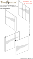
Photo 3. First view of units placed
next to each other
Photo 1. The units should be lifted
by the bracing only
Photo 2. DO NOT lift the units by
anything but the bracing

Concepts Installation Manual
7
For customer service, call (800) 733-8829, (800) 773-8821, Fax (989) 773-3210, www.deleld.com
Photo 4. Second view of units
placed next to each other
Photo 5. Third view of units placed
next to each other
Line Up Installation, continued
13. Install cold pans into unit. Ensure the gasket is visible. If there is no
gasket, silicone the seams.
14. Install hot wells into unit. Ensure the gasket is visible. If there is no
gasket, silicone the seams.
15. Make plumbing and drain connections on cold pans and hot wells.
Moisture collecting from improper drainage can create a
slippery surface on the floor and a hazard to employees. It is the
owner’s responsibility to provide proper drainage.
16. Plumb drains if necessary.
17. Plumb water lines if necessary.
18. Make electrical connections on cold pans and hot wells. Install hot
well control panel.
19. Install the kick plate (if required) by placing the shoulder bolt into the
key hole slot. See Photo 6. Install screws on end caps as necessary.
The kick plate will stay in place but can also be easily removed for
cleaning under the units.
20. Back panels may be removed by unscrewing the hex head screws.
21. Install counter protector as necessary.
22. Install signage, lighting and food shields as required. Instructions are
found on the following pages.
23. Unit is ready for final utility hookups.
24. Install tray slides.
25. Before the heated units are used the first time for serving:
Turn the temperature knob to “10” and heat the well for 15 minutes.
Do not be alarmed if small amount of smoke appears; this preheat
should burn off any residue or dust that has adhered to the food well
element.
26. Check electrical outlets for proper operation.
27. Function test all equipment.
Photo 6. Kick plate shoulder bolt
installed in the key hole slot
CAUTION

Concepts Installation Manual
For customer service, call (800) 733-8829, (800) 773-8821, Fax (989) 773-3210, www.deleld.com
8
Beverage Counter Installation
1. Identify where the equipment will be installed.
2. Remove the galvanized shipping braces from the bottom of the unit.
3. Place Unit #1.
4. Screw adjustable feet all the way in on the first unit. Level to work
height, usually 36” or as specified.
5. Level Unit #1 front to back and left to right by adjusting the bullet feet.
6. Use caution when placing units together to protect against damaging
the laminate.
7. Place Unit #2.
8. There are (approximately 3) holes along the top and bottom sides.
Thread a 1/4-20 x 1” bolt through the unit 1 bracing hole, two supplied
washers and unit 2 bracing hole. Secure with a nut. Repeat for each
hole. Do not tighten until Unit #2 is level.
9. Level Unit #2 front to back and left to right by adjusting the bullet feet.
10. Tighten the nuts and bolts that connect Unit #1 and #2.
11. Repeat steps 6-10 as you add each additional unit.
12. Have the top installed. Verify it is secure and level.
13. Plumb drains if necessary.
14. Plumb water lines if necessary.
15. Install the kick plate (if required) by placing the shoulder bolt into the
key hole slot. See Photo 6. Install screws on end caps as necessary.
The kick plate will stay in place but can also be easily removed for
cleaning under the units.
16. Back panels may be removed by unscrewing the hex head screws.
17. Beverage counter weight limit is 600 pounds per 48 linear inches.
18. If the beverage counter has a drop in unit, ensure the gasket in visible.
If there is no gasket, silicone the seams around the drop in.

Concepts Installation Manual
9
For customer service, call (800) 733-8829, (800) 773-8821, Fax (989) 773-3210, www.deleld.com
Tower Module Installation
1. Identify where the equipment will be installed.
2. Level the flanged feet and bolt to the floor.
3. Install the gooseneck lighting:
Note: The side of the connection post with (2) metallic tabs
aligns with the side of the track with the (2) copper strips.
A. Pull down on the connection box collar, push the connection
post into the track and then rotate it 90 degrees until it locks
into place.
B. If the light is mounted with the (2) metallic tabs toward the
side of the track with only (1) copper strip, the light will not
work. To correct this, simply pull down on the connection
box collar and twist it until it is released from the track.
Then, rotate it 180 degrees and mount back into the track
using the directions above.
C. To move the light, pull down on the connection box collar
and twist 90 degrees. Slide to the desired location and turn
back 90 degrees.
4. Follow installation instructions provided with menu boards (if
this option was ordered with the tower module).
5. Verify the module is plugged into a receptacle and the Reach-In
is plugged into the GFCI receptacle. If lights were provided, turn
on the ON/OFF switch on the back of the tower.
6. Slide the Reach-In in place.

Concepts Installation Manual
For customer service, call (800) 733-8829, (800) 773-8821, Fax (989) 773-3210, www.deleld.com
10
Fixed Height Signage Installation
1. Verify that black square collars are mounted in the 2”
square holes in the unit top. If they are not, locate them
in the crate and place them back in the holes in top.
2. Make sure the push pins are removed from the mounting
brackets in the bottom of the base.
3. With a person supporting each post of the signage, pick
up and hold vertically over top of the collared holes in
top.
4. If electrical cord is coming out the bottom of one of the
posts, lower it through the collared hole.
5. Next, lower signage posts down through collared holes
in top.
6. Secure in place by sliding push pin through bracket and
post.
7. If electrical cord is present, plug into the outlet in the
base.
Prepare base.
Signage post installed in base.

Concepts Installation Manual
11
For customer service, call (800) 733-8829, (800) 773-8821, Fax (989) 773-3210, www.deleld.com
To mount decorative lamps:
Note: The connection post with (2) metallic tabs aligns with
the side of the track with the (2) copper strips
1. Pull down on the tab on the side of the lamp’s connection
box, push the connection post up into the track, then
rotate it 90 degrees until the connector locks into place.
2. If the light is mounted with the (2) metallic tabs toward
the side of the track with only (1) copper strip, the light
will not work. To correct this, simply pull down on the
tab on the side of the lamp’s connection box and twist it
90 degrees until it releases from the track. Then, rotate
it 180 degrees and mount back into the track using the
directions above.
To mount flexible spotlights:
Note: The side of the connection post with (2) metallic tabs
aligns with the side of the track with the (2) copper strips.
1. Pull down on the connection box collar, push the connection
post up into the track and then rotate it 90 degrees until it
locks into place.
2. If the light is mounted with the (2) metallic tabs toward
the side of the track with only (1) copper strip, the light
will not work. To correct this, simply pull down on the
connection box collar and twist it until it is released from
the track. Then, rotate it 180 degrees and mount back into
the track using the directions above.
3. To move the light, pull down on the connection box collar
and twist 90 degrees. Slide to the desired location and turn
back 90 degrees.
4. Turn switch ON.
5. Check for proper operation.
Signage Lighting Installation
Locate the metallic tabs and strips.
Decorative lamp installation steps.
Flexible spotlight installation steps.

Concepts Installation Manual
For customer service, call (800) 733-8829, (800) 773-8821, Fax (989) 773-3210, www.deleld.com
12
Figure 1. Food shield over holes
Figure 2. Flange dimensions
FlexiShield
®
Food Shields Installation
1. Set food shield on base unit. See Figure 1.
2. Line base over holes.
• Install screws (provided) into predrilled holes. See Figure 2.
• Place 2 dabs of silicone on screws and place cover over screws.
3. Make any necessary electrical connections.
4. If applicable test lights, heat lamps etc.
5. Adjust glass for proper alignment and ensure that all hardware is
tightened securely.
6. Clean food shield and glass with mild soap and water.
FlexiShield® food shields are to be used as food and counter protection
only and should not be used in any other way.
The hand sink is to be used for hand washing
only, not for consumption.
Hot water heater MUST be filled with water
before connecting the water heater to power
to prevent damage to the heater.
The fresh water and waste water containers are located in
the base of the sink compartment on the right. The fresh
water containers are on the left with clear vinyl tubing
and waste water tanks are on the right with a rigid drain
tube. Two fresh water and two waste water containers
are provided with each unit.
To add water to the fresh water container, remove the
cap the vinyl tubing is connected to on the container by
pressing the button on the cap and pull out the cap from
the container. Pull the container out of the sink base and
unscrew the cap of the fill access hole at the back of the
container. Fill the container with water and screw the cap
back on at the back of the container and push the cap with
the vinyl tubing back into place at the front. Make sure
there are no kinks in the clear vinyl tubing.
Verify the black waste arm at the end of the drain line is in
the hole on the waste container.
Before Operating The Sink:
Water heater MUST be filled with water before connecting
the water heater to power to prevent damage to the heater.
Before plugging the sink into a wall receptacle, verify the
water pump only is plugged into the GFCI receptacle in
the base of the unit. If the water heater is plugged in,
unplug it until the heater has been filled with water. Put
the switch and the breaker to the “ON” position in the
base of the unit. Make sure the GFCI receptacle is ON.
To fill the water heater with water, turn on the hot water
handle on the faucet until water flows. When water flows
into the sink, the water heater is filled with water. The
water heater can now be plugged into the GFCI receptacle.
Verify the water heater power switch on the front of the
heater is ON. The red light on the switch will stay on until
it has reached the set temperature.
Mobile Hand Sink Installation

Concepts Installation Manual
13
For customer service, call (800) 733-8829, (800) 773-8821, Fax (989) 773-3210, www.deleld.com
Wiring Diagram, Heated Serving Counter
30A SWITCH
(OPTIONAL)
HA–1
HA–2
HA–3
HA–4
HA–5
HA–6
HA = HEATER ASSEMBLY
L1 G L2
20A, 3–POLE SWITCH
(OPTIONAL)
HA–1
HA–2
HA–3
HA–4
HA–5
HA–6
HA = HEATER ASSEMBLY
ALL WIRING
MINIMUM 14 AWG
250C
L1 L2 G L3
1000 W - 120V
OR 1000/1222 W -
208-230 V
HEATING ELEMENT
PILOT LIGHT
(FURNISHED)
INFINITE CONTROL
WITH “OFF”
POSITION
TO ADDITIONAL
FOOD WARMERS
LINE
WIRES
P
L1
L2
H1
H2
AMPERES
IN LINE
WIRES
208-230V,
3
PHASE
#
OF
WARMERS
120V,
1
PHASE
208V,
1 PHASE
230V,
1
PHASE
L1 L2 L3
1
8.3 4.8 5.3
2
16.7 9.6 10.6
3
25 14.4 15.9 14.4/15.9
4
33.3 19.2 21.3
5
24 26.6
6
28.8 31.3
19.2/21.3
24/26.1
28.8/31.3
14.4/15.9
14.4/15.9
19.2/21.3
19.2/21.3
14.4/15.9
19.2/21.3
28.8/31.3
28.8/31.3
Standard Single Phase Optional Three Phase

Concepts Installation Manual
For customer service, call (800) 733-8829, (800) 773-8821, Fax (989) 773-3210, www.deleld.com
14
COOLING T'STAT
CONDENSER FAN
COMPRESSOR
115V
L1
N
G
S
C
R
ON/OFF SWITCH
CONDENSER FAN
COMPRESSOR
115V
S
C
R
L1
N
G
COOLING T'STAT
CONDENSER FAN
COMPRESSOR
120V
L1
N
S
C
R
G
ON/OFF SWITCH
Wiring Diagram, Self-Contained Frost Top Serving Counter
Wiring Diagram, Self-Contained LiquiTec® Cold Pan Serving Counter
Wiring Diagram, Self-Contained Mechanically Cooled Serving Counter

Concepts Installation Manual
15
For customer service, call (800) 733-8829, (800) 773-8821, Fax (989) 773-3210, www.deleld.com
Wiring Diagram, Tower Module
Wiring Diagram, Mobile Hand Sink
PDF created with pdfFactory trial version www.pdffactory.com

Mt. Pleasant, MI
Covington, TN
980 S. Isabella Rd., Mt. Pleasant, MI 48858, U.S.A. • (989) 773-7981 or (800) 733-8829 • Fax (989) 773-3210 • www.deleld.com
Deleld reserves the right to make changes in design or specications without prior notice. ©2013 The Deleld Company. All rights reserved. Printed in the U.S.A.
DMCNCPTInstall 02/13
9291466
Thank you for choosing Delfield!
Help is a phone call away. Help our team of professional, courteous customer
service reps by having your model number and serial number available at the time
of your call (800) 733-8829.
Model: _______________________ S/N: ______________________
Installation Date: _______________
For a list of Delfield’s authorized parts depots,
visit our website at www.delfield.com
Register your Deleld warranty
online. Go to www.deleld.com
under the service tab to complete.
/