Page is loading ...

Axiom AMI by StoneL
Installation, Maintenance and
Operating instructions
7 AMI 70 en • 03/2017
StoneL publication 105408revA

7 AMI 70 en2 | Axiom AMI
StoneL publication 105408revA
Read these instructions rst!
These instructions provide information about safe handling and operation of the Axiom AMI by StoneL. If you require additional assistance, please
contact the manufacturer or manufacturer’s representative. Addresses and phone numbers are printed on the back cover.
Save these instructions.
Subject to change without notice.
All trademarks are property of their respective owners.
1 General 3
1.1 Introduction 3
1.2 Title plate markings 3
1.3 CE markings 3
1.4 Recycling and disposal 3
1.5 Safety precautions 3
1.6 Assembly drawing 4
1.7 Specications for all models 4
1.8 Pneumatic valve specications 5
1.9 Pneumatic valve schematics 5
1.10 Dimensions 6
2 Assembly and mounting 7
2.1 Instructions 7
2.2 Axiom AMI assembly gure 8
3 Maintenance, repair and installation 9
3.1 Maintenance and repair 9
3.2 Installation 9
3.3 Special conditions of use 9
4 Function specic details 10
4.1 Sensor/switching modules 10
4.1.1 SST N.O. sensor (33) 10
4.1.2 SST N.O. sensor; 240 VAC (35) 12
4.1.3 NAMUR sensor (44) 14
4.1.4 Expeditor (80) 16
4.2 Valve communication terminals (VCT) 19
4.2.1 VCT with HART diagnostics (71D) 19
4.2.2 VCT with DeviceNet™ communication (92S) 24
4.2.3 VCT with Foundation Fieldbus communication (93S) 26
4.2.4 VCT with Foundation Fieldbus communication with externally powered outputs (94S) 27
4.2.5 VCT with AS-Interface communication (96S) 28
4.2.6 VCT with AS-Interface communication with diagnostics (96D) 29
4.2.7 VCT with AS-Interface communication and extended addressing (97S) 31
4.2.8 VCT with AS-Interface with Wireless Link (96W & 97W) 32
5 Wireless Link user guide 34
5.1 Getting started 34
5.2 Home screen 34
5.3 Locked screen 34
5.4 Device detail screen 35
5.5 More information screen 36
5.6 Diagnostics screen 36
5.7 Federal Communication Commission (FCC) statement 37
6 Model/Type code 39
7 Regulatory, specic conditions of use, and product marking 40
8 Appendix 42
8.1 Controlled installation drawings 42
Table of contents

StoneL publication 105408revA
7 AMI 70 en Axiom AMI | 3
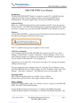
1.2 Title plate markings
The limit switch has an identication plate attached to the cover.
1. Identication plate markings:
2. Model
3. Serial number
4. Date
5. Electrical rating(s)
6. Protection class information*
7. Note
8. Warning
9. Approval marking*
10. Logo
Note
* See page38 for specic product markings.
Logo
Warning:
Note:
Sensor Ratings:
Haz. Loc.: CI I, Div 1, Gp B, C, D; CI II, Div 1, Gp E,F,G;
sample only
DateModel Serial
Approval markings
1 General
1.1 Introduction
This manual incorporates the Installation, Maintenance and Operation (IMO) instructions for the Axiom AMI series valve controllers. The Axiom
AMI is designed to provide position feedback indication and pneumatic control of on/o automated valves.
Note
The selection and use of the Axiom AMI in a specic application requires close consideration of detailed aspects. Due to the nature of the
product, this manual cannot cover all the likely situations that may occur when installing, using, or servicing the Axiom AMI. If you are uncertain
about the use of this device, or its suitability for your intended use, please contact StoneL for assistance.
1.3 CE markings
The Axiom AMI meets the requirements of European Directives and
has been marked according to the directive.
1.4 Recycling and disposal
Most Axiom AMI parts can be recycled if sorted according to material.
In addition, separate recycling and disposal instructions are available
from us. A limit switch can also be returned to us for recycling and
disposal for a fee.
1.5 Safety precautions
Do not exceed the permitted values! Exceeding the permitted values
marked on the Axiom AMI may cause damage to the switch and to
equipment attached to the switch and could lead to uncontrolled
pressure release in the worst case. Damage to the equipment and
personal injury may result.
To prevent ignition of hazardous atmospheres, replace cover before
energizing the electrical circuits. Keep cover tightly closed when in
operation.
2
5
8
4
1
3
6
7
10
9

7 AMI 70 en4 | Axiom AMI
StoneL publication 105408revA
Specications
Materials of construction
Cover Lexan® polycarbonate and Aluminum
Housing & air manifold plate Epoxy-coated anodized aluminum
Visual indicator drum Polysulfone
Visual indicator cover Polycarbonate
Fasteners Stainless steel
O-rings Nitrile compound
Operating life 1 million cycles (500,000 cycles for the Expeditor)
Temperature range See 1.8 Pneumatic valve specifications
Enclosure protection Type 4, 4X, and 6 and IP67
Warranty
Sensing & communication module Five years
Mechanical components Two years
Unit weights
Aluminum 2.48 kg / 5.45 lb
Unit dimensions
Unit height
Cover removal clearance
98.43 mm [3.87 in]
148.63 mm [5.87 in]
Position sensing
Accuracy Within 1°
Repeatability Within 1°
Setting buffer 4° from setpoint (Rotational distance from original
setpoint where switch will energize on return stroke)
Dead band 6° from setpoint (Rotational distance from original
setpoint where switch will de-energize)
Max rotational range 120°
Ratings and approvals*
See page38 or StoneL.com/approvals
* Only models listed on StoneL’s ocial website are approved per specic rating.
1.7 Specications for all models
See page10 for function specic details.
2
3
4
14
11
9
8
6
7
10
5
13
15
1
12
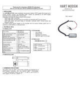
1.6 Assembly drawing
1. Title plate
2. Cover screws
3. Cover
4. Body screws
5. Body
6. Internal ground lug
7. External ground lug
8. DA/SR plug
9. Visual indicator cover
10. Visual indicator drum
retaining screw
11. Visual indicator drum
12. Visual indicator drum coupler
13. Visual indicator drive block
14. Air manifold plate mounting
screws
15. Air manifold plate orice
o-rings
16. Visual indicator cover o-ring
17. Air manifold plate
18. Actuator shaft
17
16
18

StoneL publication 105408revA
7 AMI 70 en Axiom AMI | 5
Specications
General pneumatic specications
Valve design Pilot operated spool valve
Pilot operator options Solenoid coil or Piezo
Conguration Single pilot
Dual pilot
5-way, 2-position, spring return
5-way, 2-position, shuttle piston
Flow rating 0.70 Cv (Kv = 0.60 based on ow m3/hr)
Axiom porting ¼” NPT
Manifold porting ¼” NPT
Operating pressure 40 psi to 120 psi (2.7 to 7.5 bar)
Operating temperature
Standard temp coil
Extended temp coil
-18° C to 50° C ( 0° F to 122° F)
-40° C to 80° C (-40° F to 176° F)
Operating life 1 million cycles
(500,000 cycles for the Expeditor)
Manual override Internal momentary
Optional external momentary available
Optional external latching available
Material of construction
Spool
Body
Seal spacers
Spool seals
O-rings
End caps and fasteners
Nickel plated aluminum
Epoxy-coated anodized aluminum
Polysulfone
Nitrile compound
Nitrile compound
Stainless steel
Solenoid coil specications
24 VDC/ 120 VAC Universal
Operating voltage minimum
Operating voltage maximum
Power consumption
AC current consumption
Filtration requirements
(1H, 2H, 3H, 4H, 5H, 6H)
22 VDC
130 VAC
0.6 watts
18mA
40 microns
24 VDC (1B, 2B, 3B, 4B, 5B, 6B)
Operating voltage
Power consumption
Filtration requirements
24 VDC
1.8 watts
40 microns
24 VDC (1D, 2D, 3D, 4D, 5D, 6D)
Operating voltage
Power consumption
Filtration requirements
24 VDC
0.5 Watts
40 microns
12 VDC (1E, 2E, 3E, 4E, 5E, 6E)
Operating voltage
Power consumption
Filtration requirements
Entity parameters
(Intrinsically Safe)
12 VDC (output of barrier)
0.5 watts
40 microns
Ui=28VDC; Ii=120mA; Ci=0; Li=0; Pi=1.0W
Piezo (1A, 2A, 3A, 4A, 5A, 6A)
Operating voltage
Current consumption
Temperature range
Filtration requirements
5.5 - 9.0 VDC
2.0 mA @ 6.5 VDC
-10° C to 60° C (14° F to 140° F)
Dried/30 microns
1.8 Pneumatic valve specications 1.9 Pneumatic valve schematics
Note
Pneumatic valve schematics unique to AX80S functions are on
page18 as Fig. 4 and Fig. 5 with additional information.
S1
DA
3 2
E2 E3
Actuator
Fig. 1 Single pilot spring return pneumatic valve on spring
return actuator with rebreather open
Fig. 2 Single pilot spring return pneumatic valve on double-
acting actuator with rebreather closed
Fig. 3 Axiom dual coil shuttle piston pneumatic valve
E3
SR
3
Actuator
2
S1 E2
E3
DA
3
Actuator
2
S1 E2

7 AMI 70 en6 | Axiom AMI
StoneL publication 105408revA
1.10 Dimensions
Note
Axiom AMI certied dimensional drawing can be found
under the Download tab at www.stonel.com/en/products/
axiom_AMI/
E3 E2
S1
1/4" NPT (3)
1/2" NPT (2)
3.87 in
[98.43 mm
]
2
3
1/4" NPT (2)
2.47 in
[62.88 mm]
1.88 in
[47.73 mm]
4.08 in
[103.63 mm]
6.21 in
[158.76 mm]

StoneL publication 105408revA
7 AMI 70 en Axiom AMI | 7
Caution: In order to maintain CE conformity, the Axiom
housing shall be grounded to earth potential by one of
the housing ground screws.
2 Assembly and mounting
2.1 Instructions
PLUG FOR SR
PLUG FOR DA
8
6
7
D
Detailed view from bottom of A
Steps
Refer to Axiom AMI assembly gure on page8 when performing
mounting and assembly procedures. Axiom unit and mounting kit are
supplied separately. From Axiom shipping container, ensure items A,
D, F, and G are present. From the mounting kit, ensure items E, H, I, J,
and K are present.
1. Determine if the actuator the Axiom is to be mounted on is
double-acting (DA) or spring return (SR). Ensure the DA/SR plug
(Item D) is in the corresponding port in bottom of the Axiom body.
(See detailed view from bottom of A). If the DA/SR plug is in the
incorrect position, gently remove plug with a pair of pliers and
insert into the proper orice.
2. Locate the air manifold plate (ItemK). Place the air manifold plate
on the actuator. Using an M4 allen wrench, fasten with the four air
manifold mounting screws (ItemI). Torque screws to 25 to 30 in.lbs
(2.8to 3.4Nm).
3. Place visual indicator drive block (ItemH) into slot on the actuator
shaft. Place visual indicator drum coupler (ItemG) onto the visual
indicator drive block. Next, place the visual indicator drum (ItemF)
onto the visual indicator drum coupler. Align the holes in all three
items with the threaded hole in the actuator shaft and fasten
down with the visual indicator drum retaining screw (ItemE).
Leave screw loose in order to facilitate indexing of the visual
indicator.
4. With the actuator in the closed position, center the visual indicator
drum until the OPEN quadrant is centered between the V.I. INDEX
marking on the air manifold plate. (See detailed view ofK). With
M4 allen wrench, tighten down with the visual indicator drum
retaining screw 15 to 20 in.lbs (1.7 to 2.3Nm).
5. Verify air manifold plate orice o-rings and visual indicator cover
o-ring (ItemJ) are in place.
6. Set the Axiom body (ItemA) in place. With an M4 allen wrench,
torque the Axiom body screws (ItemC) to 25 to 30 in. lbs (2.8to
3.4Nm).
7. After all wiring and sensor setting procedures have been
completed, install Axiom cover and tighten the Axiom cover
screws (Item B) with M4 allen wrench to 15 to 20 in.lbs (1.7 to
2.3Nm) .
Special notes:
• Mounting of the Axiom requires a StoneL mounting kit specic to
the actuator the Axiom is to be mounted to.
• It is recommended that thread lubricant or anti-seize be used on
the Axiom body screws (Item C) prior to assembly.
• In high cycle or high vibration applications, blue Loctite® may be
used on the air manifold mounting screws (Item I) and the visual
indicator drum retaining screw (Item E).
• It is highly recommended that exhaust ports E2 and E3 be tted
with low restriction muers or breather vent caps to prevent
ingestion of water and debris into the pneumatic valve.
Detailed view of K
V. I. INDEX
V. I. INDEX
C
L
O
S
E
D
O
P
E
N
C
L
O
S
E
D
O
P
E
N

7 AMI 70 en8 | Axiom AMI
StoneL publication 105408revA
E3
S1
E2
3
2
2.2 Axiom AMI assembly gure
A. Axiom AMI unit
B. Cover screws (4)
C. Body screws (4)
D. DA/SR plug
E. Visual indicator drum retaining screw
F. Visual indicator drum
G. Visual indicator drum coupler
H. Visual indicator drive block
I. Air manifold plate mounting screws
J. Air manifold plate orice o-rings and
Visual indicator cover o-ring
K. Air manifold plate
E
D
F
G
H
J
K
I
C
B
A

StoneL publication 105408revA
7 AMI 70 en Axiom AMI | 9
3 Maintenance, repair and installation
3.1 Maintenance and repair
No routine maintenance of Axiom units is required when installed in environments for which they are designed. If installed in severe
environments, pneumatic components may require replacement at more frequent intervals for maximum performance. Repair of Axiom units
must be done by StoneL or by qualied personnel that are knowledgeable about the installation of electromechanical equipment in hazardous
areas. All parts needed for repair must be purchased through a StoneL authorized distributer to maintain warranty and to ensure the safety and
compliance of the equipment.
3.2 Installation
Attention: If required, the Axiom housing can be
grounded to earth potential by either the internal or
external ground lug. (See Assembly drawing 1.6 items 6
and 7 on page4)
WARNING
Solenoid power supplied must be limited with a fuse or circuit
breaker rated to 2 Amps maximum.
Field wiring
• It is the responsibility of the installer, or end user, to install this
product in accordance with the National Electrical Code (NFPA 70)
or any other national or regional code dening proper practices.
• This product comes shipped with conduit covers in an eort to
protect the internal components from debris during shipment and
handling. It is the responsibility of the receiving and/or installing
personnel to provide appropriate permanent sealing devices to
prevent the intrusion of debris or moisture when stored or installed
outdoors.
• When installed in ambient temperatures over 60° C, use eld wiring
rated for 90° C.
3.3 Special conditions of use
For units with quick connect receptacles, when installed in Division 2 areas, an appropriate FM approved mating cord must be used in
conjunction with tamper proof guard at the mating point that requires a tool to remove, rendering the connection not normally arcing.

7 AMI 70 en10 | Axiom AMI
StoneL publication 105408revA
Caution: A series load resistor must be used when bench
testing in order to prevent permanent damage to the unit.
4 Function specic details
4.1 Sensor/switching modules
4.1.1 SST N.O. sensor (33)
Specications
Conguration (2) N.O. 2-wire solid state sensors
Voltage range 22 - 130 VDC/VAC
Maximum current Continuous 0.1 amps
Minimum on current 2.0 mA
Maximum leakage current 0.5 mA
Maximum voltage drop 6.5 volts @ 10 mA
7.0 volts @ 100 mA
Circuit protection Protected against short circuits and direct
application of voltage with no load.
Bench test procedure and sensor setting instructions
Power must be applied to both sensors to ensure proper circuit
operation. Use a 24VDC power supply with series load resistor, (2K -
6K Ω), connected to the 24VDC+.
1. Connect 24VDC+ to the CLOSED C (common) and OPEN C
(common) terminals. Connect 24VDC- to the CLOSED NO and
OPEN NO terminals.
2. Operate actuator to the closed position.
3. Press and hold SET CLOSED button until CLOSED LED is lit
(2seconds). Release button.
4. Operate actuator to the open position.
5. Press and hold SET OPEN button until OPEN LED is lit (2 seconds).
Release button.
6. Setpoints are retained even after power is removed.
To electrically test solenoid, apply power to the SOL PWR IN terminals
only.
Note
If using only one of the sensors for valve position feedback, the open
sensor (green) must be used.
WARNING
Do not apply external power to the SOL OUT terminals. This will
cause permanent damage to the unit.
SST
SOL OUT -
SOL OUT +
OPEN
SET
OPEN
CLOSED
SET
CLOSED
SOLENOID INPUT: 24VDC/120VAC
SOLENOID
POWER
SOL PWR IN
SOL PWR IN
OPEN NO
OPEN C
CLOSED NO
CLOSED C
(1)
(2)
(3)
(4)
(5)
(6)
(7)
(8)
Setup Instructions:
Operate Actuator to Closed
Position and Push SET
CLOSED for 2 seconds.
Operate Actuator to Open
Position and Push SET
OPEN for 2 seconds.
Wiring diagrams
Single coil solenoid
Common receptacle options pin-out
Signal
OPEN/CLOSED C
MALE (PINS)
MALE (PINS)
1
1
2
2
5
5
4
4
3
3
5-PIN MICRO CONNECTOR (M12)
5-PIN MINI CONNECTOR
CLOSED NO
OPEN NO
SOL PWR IN +
SOL PWR IN -
Pin
1
2
3
4
5

StoneL publication 105408revA
7 AMI 70 en Axiom AMI | 11
SST
SOL 1 PWR IN
SOL 1 PWR IN
OPEN
SET
OPEN
CLOSED
SET
CLOSED
SOL 2 PWR IN
SOL 2 PWR IN
OPEN NO
OPEN C
CLOSED NO
CLOSED C
(1)
(2)
(3)
(4)
(5)
(6)
(7)
(8)
(12) SOL 1 OUT -
(11) SOL 1 OUT +
(10) SOL 2 OUT -
(9) SOL 2 OUT +
Setup Instructions:
Operate Actuator to Closed
Position and Push SET
CLOSED for 2 seconds.
Operate Actuator to Open
Position and Push SET
OPEN for 2 seconds.
SOLENOID INPUT: 24VDC/120VAC
Wiring diagrams
Common receptacle options pin-out
Dual coil solenoid
Signal
OPEN/CLOSED C
MALE (PINS)
MALE (PINS)
1
1
2
2
5
6
4
5
3
4
3
6-PIN MICRO CONNECTOR (M12)
6-PIN MINI CONNECTOR
CLOSED NO
OPEN NO
SOL1 & SOL2 PWR IN
SOL1 PWR IN
Pin
1
2
3
4
5
SOL2 PWR IN6
6
4.1.1 SST N.O. sensor (33) continued

7 AMI 70 en12 | Axiom AMI
StoneL publication 105408revA
Bench test procedure and sensor setting instructions
Power must be applied to both sensors to ensure proper circuit
operation. Use a 24VDC power supply with series load resistor, (2K -
6K Ω), connected to the 24VDC+.
1. Connect 24VDC+ to the CLOSED C (common) and OPEN C
(common) terminals. Connect 24VDC- to the CLOSED NO and
OPEN NO terminals.
2. Operate actuator to the closed position.
3. Press and hold SET CLOSED button until CLOSED LED is lit
(2seconds). Release button.
4. Operate actuator to the open position.
5. Press and hold SET OPEN button until OPEN LED is lit (2seconds).
Release button.
6. Setpoints are retained even after power is removed.
To electrically test solenoid, apply power to the SOL PWR IN terminals
only.
Note
If using only one of the sensors for valve position feedback, the open
sensor (green) must be used.
Caution: A series load resistor must be used when bench
testing in order to ensure proper module operation.
4.1 Sensor/switching modules
4.1.2 SST N.O. sensor; 240 VAC (35)
Specications
Conguration (2) NO 2-wire solid state sensors
Voltage range 20 - 250 VAC, 8 - 250 VDC
Minimum on current 2.0 mA
Maximum continuous current 0.1 amps
Maximum leakage current 0.5 mA
Maximum voltage drop 6.5 volts @ 10 mA
7.5 volts @ 100 mA
Circuit protection Protected against direct application of voltage up
to 20 VDC/125 VAC.
No protection at 240 VAC
WARNING
Do not apply external power to the SOL OUT terminals. This will
cause permanent damage to the unit.
Wiring diagrams
Single coil solenoid
240V
SST
SOL OUT -
SOL OUT +
OPEN
SET
OPEN
CLOSED
SET
CLOSED
SENSOR INPUT: 8-250VDC/20-250VAC
SOLENOID INPUT: 20-60VDC/20-250VAC
SOLENOID
POWER
SOL PWR IN
SOL PWR IN
OPEN NO
OPEN C
CLOSED NO
CLOSED C
(1)
(2)
(3)
(4)
(5)
(6)
(7)
(8)
Setup Instructions:
Operate Actuator to Closed
Position and Push SET
CLOSED for 2 seconds.
Operate Actuator to Open
Position and Push SET
OPEN for 2 seconds.
Common receptacle options pin-out
Signal
OPEN/CLOSED C
MALE (PINS)
MALE (PINS)
1
1
2
2
5
5
4
4
3
3
5-PIN MICRO CONNECTOR (M12)
5-PIN MINI CONNECTOR
CLOSED NO
OPEN NO
SOL PWR IN +
SOL PWR IN -
Pin
1
2
3
4
5

StoneL publication 105408revA
7 AMI 70 en Axiom AMI | 13
Wiring diagrams
240V
SST
SOL 1 PWR IN
SOL 1 PWR IN
OPEN
SET
OPEN
CLOSED
SET
CLOSED
SOL 2 PWR IN
SOL 2 PWR IN
OPEN NO
OPEN C
CLOSED NO
CLOSED C
(1)
(2)
(3)
(4)
(5)
(6)
(7)
(8)
(12) SOL 1 OUT -
(11) SOL 1 OUT +
(10) SOL 2 OUT -
(9) SOL 2 OUT +
Setup Instructions:
Operate Actuator to Closed
Position and Push SET
CLOSED for 2 seconds.
Operate Actuator to Open
Position and Push SET
OPEN for 2 seconds.
SENSOR INPUT: 8-250VDC/20-250VAC
SOLENOID INPUT: 20-60VDC/20-250VAC
Common receptacle options pin-out
Signal
OPEN/CLOSED C
MALE (PINS)
MALE (PINS)
1
1
2
2
5
6
4
5
3
4
3
6-PIN MICRO CONNECTOR (M12)
6-PIN MINI CONNECTOR
CLOSED NO
OPEN NO
SOL1 & SOL2 PWR IN
SOL1 PWR IN
Pin
1
2
3
4
5
SOL2 PWR IN6
6
4.1.2 SST N.O. sensor; 240 VAC (35) continued
Dual coil solenoid

7 AMI 70 en14 | Axiom AMI
StoneL publication 105408revA
4.1 Sensor/switching modules
4.1.3 NAMUR sensor (44)
Specications
Conguration (2) NAMUR sensors (EN 60947-5-6; IS)
Voltage range 7 - 24 VDC
Current ratings Target present
Target absent
Current < 1.0 mA
Current > 2.1 mA
Use with intrinsically safe repeater barrier. NAMUR sensors conform to EN 60947-5-6 standard.
Intrinsically safe solenoid coil (E)
Voltage 24 VDC to input of solenoid barrier*
12 VDC from output of solenoid barrier to coil
*Note: Use of an intrinsically safe 24 VDC solenoid barrier with internal impedance, or end-
to-end resistance, of 250 to 305 ohms required for proper solenoid coil operation.
Bench test procedure and sensor setting instructions
Power must be applied to both sensors to ensure proper circuit
operation. Use a 24VDC power supply. A series load resistor is not
required when bench testing.
1. Connect 24VDC+ to the CLOSED + and OPEN + terminals.
Connect 24VDC- to the CLOSED - and OPEN - terminals.
2. Operate actuator to the closed position.
3. Press and hold SET CLOSED button until OPEN LED goes out
(2seconds). Release button.
4. Operate actuator to the open position.
5. Press and hold SET OPEN button until CLOSED LED goes out
(2seconds). Release button. Both OPEN and CLOSED LEDs will be
lit during mid-travel.
6. Setpoints are retained even after power is removed.
Note
If using only one of the sensors for valve position feedback, the open
sensor (green) must be used.
WARNING
Do not apply external power to the SOL OUT terminals. This will
cause permanent damage to the unit.
Reference controlled installation drawing #105157 for
proper intrinsic safe installation details. Find document
in the Appendix on page40 or at www.StoneL.com/
en/products/axiom/installation-manuals
STOP
NAMUR
SOL +
SOL -
OPEN
SET
OPEN
CLOSED
SET
CLOSED
SOLENOID
POWER
SOL PWR +
SOL PWR -
OPEN +
OPEN -
CLOSED +
CLOSED -
(1)
(2)
(3)
(4)
(5)
(6)
(7)
(8)
Setup Instructions:
Operate Actuator to Closed
Position and Push SET
CLOSED for 2 seconds.
Operate Actuator to Open
Position and Push SET
OPEN for 2 seconds.
Wiring diagrams
Single coil solenoid
Common receptacle options pin-out
Signal
OPEN +
MALE (PINS)
MALE (PINS)
1
1
2
2
5
6
4
5
3
4
3
6-PIN MICRO CONNECTOR (M12)
6-PIN MINI CONNECTOR
OPEN -
SOL PWR +
CLOSED +
CLOSED -
Pin
1
2
3
4
5
SOL PWR -6
6

StoneL publication 105408revA
7 AMI 70 en Axiom AMI | 15
NAMUR
SOL 1 PWR +
SOL 1 PWR -
OPEN
SET
OPEN
CLOSED
SET
CLOSED
SOL 2 PWR +
SOL 2 PWR -
OPEN +
OPEN -
CLOSED +
CLOSED -
(1)
(2)
(3)
(4)
(5)
(6)
(7)
(8)
(12) SOL 1 OUT -
(11) SOL 1 OUT +
(10) SOL 2 OUT -
(9) SOL 2 OUT +
Setup Instructions:
Operate Actuator to Closed
Position and Push SET
CLOSED for 2 seconds.
Operate Actuator to Open
Position and Push SET
OPEN for 2 seconds.
Wiring diagrams
Dual coil solenoid
Typical basic intrinsically safe circuits
NAMUR sensor circuit
Solenoid circuit
4.1.3 NAMUR sensor (44) continued
** Barrier o
ff state (target of
f): current in NAMUR sensor circuit >2.1 mA
Barrier on
state (target on): current in NAMUR sensor circuit <1.0 mA
power
source
Hazardous area
NAMUR
repeater
barrier
24 VDC
computer input
8 VDC
I = 0.5mA to 5.0mA**
NAMUR sensor
power
source
Hazardous area
solenoid
barrier**
24 VDC
computer output
12 VDC
solenoid coil
** Use of an intrinsically safe 24 VDC solenoid barrier with internal
impedance, or end-to-end resistance, of 250 to 305 ohms required for
proper operation of StoneL’s intrinsically safe solenoids.
Common receptacle options pin-out
Signal
SOL1 PWR IN +
MALE (PINS)
7
2
1
5
6
4 3
8-PIN MICRO CONNECTOR (M12)
8-PIN MINI CONNECTOR
SOL1 PWR IN -
CLOSED +
CLOSED -
SOL2 PWR IN +
Pin
1
2
3
4
SOL2 PWR IN -
OPEN +
OPEN -
5
6
7
8
MALE (PINS)
1
7 3
2
8
8
6 4
5

7 AMI 70 en16 | Axiom AMI
StoneL publication 105408revA
4.1 Sensor/switching modules
4.1.4 Expeditor (80)
Specications
Position feedback control (AI) 4-20 mA loop, 9 - 35 VDC
Intermediate position control (AO) 4-20 mA loop, 9 - 35 VDC
Position monitoring accuracy +/- 1° of rotation
Intermediate control accuracy +/- 3° of rotation
Solenoid voltage 24 VDC (conventional models)
12 VDC (intrinsic safety models)
Solenoid power 0.5 watt (20 mA @ 24 VDC)
0.5 watt intrinsically safe (40 mA @ 12 VDC)
Cycle life 500,000 cycles (full cycles with intermediate
positioning, cycle life may vary depending on
intermediate toggling)
Expeditor
PRI SOL -
OPEN
SET
OPEN
CLOSED
SET
CLOSED
PRIMARY SOLENOID
SECONDARY SOLENOID
PRI SOL +
SOL PWR -
SOL PWR +
POS FB -
POS FB +
CNTRL IN -
(3)
SEC SOL -
SEC SOL +
(1)
(2)
(4)
(5)
(6)
(7)
(8)
(9)
CNTRL IN +
(10)
Setup Instructions:
1. With solenoid power on, push
and hold both buttons until the
RED and GREEN LEDs turn on.
Actuator will either close or open
depending on type.
2. Push SET CLOSED or SET
OPEN depending on whether the
valve is closed or open.
3. Push the other SET button to
move the actuator to the opposite
position.
4. Push SET CLOSED or SET
OPEN depending on whether the
valve is closed or open.
Wiring diagram
Signal
CNTRL IN +
MALE (PINS)
MALE (PINS)
1
1
2
2
5
6
4
5
3
4
3
6-PIN MICRO CONNECTOR (M12)
6-PIN MINI CONNECTOR
CNTRL IN -
POS FB +
POS FB -
SOL PWR +
Pin
1
2
3
4
5
SOL PWR -6
6
Common receptacle options pin-out

StoneL publication 105408revA
7 AMI 70 en Axiom AMI | 17
Description of operation
The Axiom expeditor is a valve monitoring and control package
for quarter-turn actuators that require the valve to stop in an
intermediate position. Position feedback and intermediate position
control are accomplished by two separate 4-20mA loops.
The Axiom expeditor C-module is powered by a 4-20mA loop
through the position feedback terminals. Therefore, this input is
required to be connected to an analog input for calibration and
basic operation of the expeditor. The position feedback provides a
4mA signal for valve closed position, a 20mA signal for valve open
position, and a 4-20mA feedback signal for any intermediate position.
Intermediate positioning control requires a 4-20mA signal from an
analog output to the control input terminals of the C-module. The
Axiom expeditor controls the valve/actuator position by the use of
an integral dual coil pneumatic solenoid valve. Solenoid power is
required from a single discrete output. This single channel provides
power to both the primary and secondary pilot valve coils and must
be either 24VDC for nonincendive equipment applications or 12VDC
for intrinsic safety applications (model/application dependent).
Basic operation
Voltage is applied to the solenoid power terminals. This will cause the
actuator to fully stroke. Simply remove the solenoid power voltage
to fully stroke the valve/actuator to the fail position. The position
feedback will provide valve position indication, (4mA for the closed
position or 20mA for the open position).
Intermediate position control operation
In this mode the expeditor will operate as in basic mode until a
4-20mA signal from an analog output is applied to the control input
terminals. If solenoid power is applied, the valve/actuator will drive to
the intermediate control position dictated by the analog output. For
example, if the analog output is providing a 12mA signal, the valve/
actuator will drive to the 50% position. The position feedback signal
will provide an accurate 4-20mA signal of valve position that can be
monitored by an analog position feedback device.
Note
Solenoid power must be continuously applied for intermediate
position control operations. Should the solenoid power be removed
at any time, the valve/actuator will drive to the failed position.
WARNING
Do not apply external power to the primary or secondary
solenoid terminals. This will cause permanent damage to the unit.
Basic installation example
4-20 mA
IN
24 VDC
24 VDC
4-20 mA
OUT
24 VDC
Axiom expeditor
Computer control system
PRI SOL -
PRI SOL +
SOL PWR -
SOL PWR +
POS FB -
POS FB +
CNTRL IN -
(3)
SEC SOL -
SEC SOL +
(1)
(2)
(4)
(5)
(6)
(7)
(8)
(9)
CNTRL IN + (10)
4.1.4 Expeditor (80) continued

7 AMI 70 en18 | Axiom AMI
StoneL publication 105408revA
Calibration and operating procedures
The Position Feedback terminals (POS FB+ and POS FB-) must be
connected to a 4-20mA Analog Input (or 24VDC power source when
bench testing) and the Solenoid Power terminals (SOL PWR+ and SOL
PWR-) must be connected to a Discrete Output (or 24VDC power
source when bench testing) and energized to perform this procedure.
Note
POS FB+ and POS FB- will output 12mA until both open and closed
positions are set.
1. With the Axiom Expeditor connected to the control system (or
24VDC power sources when bench testing) as instructed above,
press and hold both the SET OPEN and SET CLOSED push buttons
until both the green OPEN and red CLOSED LEDs light, then
release. Both OPEN and CLOSED LEDs will be ashing.
The actuator will either open or close, depending on whether it is
congured as failed open or failed closed.
2. If the valve/actuator is in the open position from step 1,
momentarily press the SET OPEN push button and release.
The green OPEN LED will be lit and the open position setpoint
programmed.
Or
If the valve/actuator is in the closed position from step 1,
momentarily press the SET CLOSED push button and release. The
red CLOSED LED will be lit and the closed position setpoint will be
programmed.
3. Based upon the results of step 2, if the green LED is lit, press and
release the SET CLOSED push button, or if the red LED is lit, press
and release the SET OPEN push button. This will cause the valve/
actuator to stroke to that position.
4. After the valve/actuator has fully opened or closed, press and
release the corresponding SET OPEN or SET CLOSED push button.
This will program that position setpoint and cause the valve/
actuator to complete full open/closed cycle.
5. Upon completion of the open/closed cycle, if the valve/actuator
is in the open position and only the green OPEN LED is lit or if the
valve/actuator is in the closed position and only the red CLOSED
LED is lit, unit is ready for normal operation.
Note
If upon completion of the open/closed cycle and both the green
OPEN LED and red CLOSED LED are alternately ashing, this indicates
the actuator open/close time is too fast and the StoneL supplied
adjustable air ow restrictors need to be installed between the
Expeditor unit and the actuator. Once the air ow restrictors are
installed, the calibration procedure will need to be performed again.
6. Intermediate position control can be veried by applying a
4-20mA signal to the CNTRL+ and CNTRL- terminals while the
solenoid is energized. Verify valve/actuator drove to desired
intermediate position. Unit is now ready for normal operation.
Pneumatic valve schematics
4.1.4 Expeditor (80) continued
Caution: Read all instructions prior to performing this
procedure.
Caution: Valve/actuator will automatically stroke while
performing this procedure.
Fig. 4 Expeditor pneumatic valve on spring return actuator
Fig. 5 Expeditor pneumatic valve on double-acting actuator
E1/ E3
DA/SR plug
3
Spring return
actuator
Axiom control
Flow restrictor
(if required)
Primary solenoid
Secondary solenoid
2
S1
E1/ E3
DA/SR plug
3
Double-acting
actuator
Axiom control
Flow restrictors
(if required)
Primary solenoid
Secondary solenoid
2
S1

StoneL publication 105408revA
7 AMI 70 en Axiom AMI | 19
4.2 Valve communication terminals (VCT)
4.2.1 VCT with HART diagnostics (71D)
Specications
Communication protocol HART version 7.0
Position feedback Current output
Voltage
Loop resistance
4-20 mA
14-35 VDC (24 VDC nominal)
250 ohms (min) to
400 ohms (max) at 24VDC
Pressure accuracy + 1% of full scale
Solenoid power
Conventional models (D)
Intrinsic safety models (E)
0.5 watt (0.02 amps @ 24VDC)
0.5 watt (0.04 amps @ 12VDC)
Inputs and outputs
The Axiom HART C-module
comes with an 8-pole terminal
block. The terminal block
numbering is as indicated
(1)
(2)
(3)
(4)
(5)
(6)
(7)
(8)
SOL - (factory wired to solenoid coil)
SOL+ (factory wired to solenoid coil)
SOL PWR - (power for solenoid coil)
SOL PWR+ (power for solenoid coil)
GND (connected to unit internal ground screw)
GND (internally connected to terminal #5)
HART - (HART return)
HART+ (HART input)
Bench test procedure
To test sensors, use a 24VDC power supply. No series load resistor is
required.
1. Apply power across the HART+ and HART- terminal points.
2. Operate actuator to the closed position
3. Press and hold SET CLOSED button until CLOSED LED is lit
(2seconds). Release button.
4. Operate actuator to the open position.
5. Press and hold SET OPEN button until OPEN LED is lit (2 seconds).
Release button.
6. Setpoints are retained even after power is removed.
Note
A functioning HART network is required to do basic setup and
all other functionalities provided by the HART Sensing and
Communications Module.
WARNING
Do not apply external power to the output terminals. This will
cause permanent damage to the unit.
SOL -
SOL +
OPEN
SET
OPEN
CLOSED
SET
CLOSED
Diagnostics: Blinking LED indicates problem
SOLENOID POWER
STUCK SPOOL/PILOT
STUCK PROCESS
VALVE/ACTUATOR
BAD SOLENOID COIL
BAD AIR SUPPLY
PRESSURE
SOL PWR -
SOL PWR +
GND
GND
HART -
HART +
(1)
(2)
(3)
(4)
(5)
(6)
(7)
(8)
Setup Instructions:
1. Turn off solenoid. Push and
hold both buttons until the RED
and GREEN LEDs turn on.
2. Push SET CLOSED if closed or
push SET OPEN if open.
3. Turn on solenoid. Push SET
OPEN if open or push SET CLOSED
if closed.
Wiring diagram
Common receptacle options pin-out
Signal
HART -
MALE (PINS)
MALE (PINS)
1
1
2
2
5
5
4
4
3
3
5-PIN MICRO CONNECTOR (M12)
5-PIN MINI CONNECTOR
HART +
SOL PWR -
Ground
SOL PWR +
Pin
1
2
3
4
5
Calibration instructions
1. With the sensor and communication module (CCM) wired to the
control system, power applied to the HART+/- terminals, and
solenoid power turned o, press and hold both SET OPEN and
SET CLOSED buttons until both the red and green LEDs turn on.
Release buttons.
2. If the valve/actuator is in the closed position, push SET CLOSED
button and release. If the valve/actuator is in the open position,
push SET OPEN button and release.
3. Energize the solenoid.
4. If the valve/actuator goes to the closed position, push SET CLOSED
button and release. If the valve/actuator goes to the open position,
push SET OPEN button and release.
5. Setpoints are retained even after power is removed.

7 AMI 70 en20 | Axiom AMI
StoneL publication 105408revA
Description of operation
The Axiom HART is a valve-monitoring package for ¼ turn actuators.
It has the added capability of providing diagnostic information on
the pilot solenoid, spool valve, and actuator. The device will also store
historical data on each cycle.
The Axiom HART (Highway Addressable Remote Transducer) takes
advantage of the HART protocol’s ability to provide position feedback
as well as device variables over 2 wires. HART communication
is master/slave over a 4-20mA current loop. Communication is
superimposed on the current loop.
The HART C-module is powered by 24VDC (14VDC min). A HART
modem and master are required to communicate with the C-module.
The C-module will feedback 4mA for closed or 20mA for open. It will
also provide feedback for any intermediate position.
Solenoid power (24VDC) is required by the C-module to power
the pilot solenoid. For IS applications a special 12VDC IS coil will be
provided.
Connecting the device
The HART C-module requires a power source of 24VDC. A 250-
400ohm resistor is required between the power source and the
HART C-module. A HART modem may be attached across the resistor
(or HART unit) to enable communication with the host. See basic
installation example below.
Basic operation
To move the actuator/valve, simply apply 24VDC to the solenoid
power input and the actuator will move from closed (4mA) to open
(20mA). A yellow LED will light on the C-module to indicate power
was applied to the solenoid.
Basic installation example
LED indications
OPEN (green) and CLOSED (red) LEDs
Will light when the valve position gets within four degrees of either
the open or closed setpoint. The valve needs to rotate six degrees
away from either the open or closed setpoint in order for that
respective LED to turn o.
SOLENOID POWER (yellow)
Lights whenever solenoid power is applied.
BAD SOLENOID COIL (red)
Flashes at 2Hz whenever there is an open or a short on the pilot coil.
BAD AIR SUPPLY PRESSURE (red)
If the input supply air pressure is below 40psi or above 110psi for
3seconds, the LED will ash at 2Hz rate. The 40psi/110psi pressure
levels are factory defaults and may be changed through a HART
command.
STUCK SPOOL/PILOT (red)
If pressure to move the actuator is not present within 5 seconds after
applying or removing power to the solenoid, and if there is not a bad
solenoid or a bad air supply pressure fault, then the LED will ash
at 2Hz rate. The time out is ¼ of the stroke time (5 second with a
20second stroke time default).
STUCK PROCESS VALVE/ACTUATOR (red)
If, after 20 seconds (factory default), the position sensor doesn’t
reach its end of travel after the power to the coil has been applied
or removed and if there are no other alerts, then the LED will ash at
2Hz rate. The 20 second stroke time is a factory default and may be
changed through a HART command.
4.2.1 VCT with HART diagnostics (71) continued
Solenoid
SOL -
SOL +
SOL PWR -
SOL PWR +
Internally
connected
GND
PE
GND1
+
-
GND1
+
-
24 VDC source
(solenoid)
24 VDC source
(HART)
GND
HART -
HART +
(1)
(2)
(3)
(4)
(5)
(6)
(7)
(8)
HART interface
(modem)
Analog input card with integrated HART
Host system
/