Honeywell EC7830A, RM7830A, EC7850A, RM7850A Operating instructions
- Type
- Operating instructions

INSTALLATION INSTRUCTIONS
32-00198-03
SIL3
Capable
0063
EDITION 03.20 · 32-00198–03 · EN
EN
DE, EN, ES, FR, IT, RU – www.docuthek.com
EC7830A, RM7830A,
EC7850A, RM7850A
7800 SERIES Relay Modules
APPLICATION
The Honeywell EC/RM7830A and EC/RM7850A are
microprocessor-based integrated burner controls for
applications that meet European safety standards (CE) for
automatically fired gas, oil, or combination fuel single
burner full modulation (EC/RM7850A) or on/off
(EC/RM7830A) applications. The EC/RM7830A;
EC/RM7850A system consists of a relay module, subbase,
amplifier, and purge card. Options include keyboard
display module (KDM), Data ControlBus™ Module and
remote display mounting.
Functions provided by the EC/RM7830A and
EC/RM7850A include automatic burner sequencing,
flame supervision, system status indication, system or
self-diagnostics and troubleshooting. Text readout on the
Keyboard Display Module is available in various
languages.
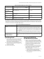
This document covers the following 7800 Series Relay
Modules:
This document provides installation and static checkout
instructions. Other applicable publications are:
1000-series 2000-series
EC7830A1033 EC7830A2033
EC7830A1066 EC7830A2066
EC7850A1072 EC7850A2072
EC7850A1080 EC7850A2080
EC7850A1122 EC7850A2122
RM7830A1003 RM7830A2003
RM7830A1029 RM7830A2029
RM7850A1001 RM7850A2001
RM7850A1019 RM7850A2019
Form
Number Description
32-00110 S7800A2142 4-line LCD Keyboard Display
Module Product Data
32-00166 204729A/C KDM NEMA4 Covers for 4-line
LCD KDM
32-00235 R7824, R7847, R7848, R7849, R7861,
R7886 Flame Amplifiers for the 7800
SERIES Product Data
65-0084 Q7800A,B 22-Terminal Wiring Subbase
Product Data
65-0089 ST7800A,C Plug-In Purge Timer
65-0090 S7800A Keyboard Display Module Product
Data
65-0091 S7810A Data ControlBus™ Module
Product Data
65-0095 S7820 Remote Reset Module Product
Data
65-0097 221729C Dust Cover Packing Instructions
65-0131 221818A Extension Cable Assembly
Product Data
65-0228 S7810B Multi-Drop Switch Module
Product Data
65-0229 7800 SERIES Relay Modules Checkout
and Troubleshooting Product Data
65-0249 S7810M ModBus Module (For CE ,
Modbus module S7810M1029 only).
65-0295 50023821-001/2 KDM NEMA4 Covers for
classic 2-line VFD KDM

EC7830A, RM7830A, EC7850A, RM7850A 7800 SERIES RELAY MODULES
32-00198—03 2
SPECIFICATIONS
Electrical Ratings (See Tables 3A, 3B, 3C and 3D):
Voltage and Frequency:
RM7830A and RM7850A:
120 Vac (+10/-15%), 50/60 Hz (±10%).
EC7830A and EC7850A:
220-240 Vac (+10%/-15%), 50/60 Hz (±10%)
Power Dissipation: 10W maximum.
Maximum Total Connected Load: 2000 VA.
Fusing Total Connected Load: 15A maximum, Fast Blow,
type SC or equivalent.
Environmental Ratings:
Ambient Temperature:
Operating: -40°F to 140°F (-40°C to +60°C).
Storage: -40°F to 150°F (-40°C to +66°C).
Humidity: 85% relative humidity continuous, noncon-
densing.
Vibration: 0.5G environment.
SIL 3 Capable:
SIL 3 Capable in a properly designed Safety Instrumented
System. See form 65-0312 for Certificate Agreement
Approvals
Federal Communications Commission:
Part 15, Class B, Emissions.
Exida: IEC/EN 61508:2010 Parts 1-7, SIL 3 capable.
AGA Certificate # 5097
EAC Russia
Factory Mutual Approved: Report No. 1V9A0.AF (for
RM7830A1003, RM7830A1029, RM7850A1001,
RM7850A1019, RM7830A2003, RM7830A2029,
RM7850A2001, RM7850A2019)
European Directives
Gas Appliances Regulation: 2016/426/EU GAR
Low Voltage Directive: 2014/35/EU LVD.
EMC Directive: 2014/30/EU EMC (Immunity Emission
conformity can only be verified in combination with
the appliance).
KIWA: certificate # 18GR0996/00, PIN 0063CT1466
Applicable Standards:
EN 298:2012 Automatic burner controls
EN 60335-2-102 Household and similar electrical
appliances
EN 746-2 Industrial thermo-processing - fuel handling
systems
Please note the following to comply with EN60730 for
remote mounting of the KDM and/or remote reset module.
It is necessary to provide electrical separation using
insulation at least equivalent to double or reinforced
insulation. This can be accomplished by either:
1. Optically isolating the communication and/or
remote reset lines from the control cabinet or
2. Providing physical separation from the
communication and/or remote reset lines using
electrical conduit and a 50023821-001/002 (for
S7800A 2-line VFD) or 204729A/C (for S7800A 4-
line LDC) Remote Display Cover Assembly or other
suitable enclosure that meets NEMA4 class of
protection.
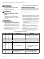
INSTALLATION
When Installing this Product…
1. Read these instructions carefully. Failure to follow
them could damage the product or cause a
hazardous condition.
2. Check the ratings given in the instructions and
marked on the product to make sure the product is
suitable for the application.
3. Installer must be a trained, experienced, flame
safeguard service technician.
4. After installation is complete, check out the product
operation as provided in these instructions.
WARNING
Fire or Explosion Hazard.
Can cause severe injury, death or property
damage.
Carefully follow safety requirements when
installing a burner control.
WARNING
Electrical Shock Hazard or Equipment Damage
Hazard.
Can cause severe injury, death or equipment
damage.
Disconnect power supply before beginning
installation. More than one disconnect may be
involved.
Continuous Operation Note
Non-check amplifiers cannot be used in continuous
operation (per EN298). For continuous operation only
ampli-check (rectification flame sensors only) or
shutter/self-check (optical flame sensors only) flame
amplifiers are used.
Non-check amplifiers trigger the device to automatically
recycle after 24 hours when in a continuous run mode. Per
EN298, the use of ampli-check amplifiers with non-self-
check UV flame sensors is not allowed for continuous
operation.
IMPORTANT
1. Wiring connections for the relay modules are unique;
refer to Fig. 4 and 5 or the appropriate Specifications
for individual subbase wiring.
2. Wiring must comply with all applicable codes, ordi-
nances and regulations.
3. Wiring must comply with NEC Class 1
(Line Voltage) wiring.
4. Loads connected to the EC/RM7830A and
EC/RM7850A must not exceed those listed on the
relay module label or the Specifications; see Table 1.
5. Limits and interlocks must be rated to simultane-
ously carry and break current to the ignition trans-
former, pilot valve, and main fuel valve(s).
6. All external timers must be listed or
component-recognized by authorities who have
proper jurisdiction.

EC7830A, RM7830A, EC7850A, RM7850A 7800 SERIES RELAY MODULES
332-00198—03
7. For on-off gas-fired systems, some authorities who
have jurisdiction prohibit the wiring of any limit or
operating contacts in series between the flame
safeguard control and the main fuel valve(s).
8. Two flame detectors can be connected in parallel
with the exception of C7915 Infrared Flame Detec-
tors, C7927 or C7961 Ultraviolet Flame Detectors.
9. This equipment generates, uses and can radiate radio
frequency energy and, if not installed and used in
accordance with the instructions, can cause
interference with radio communications. It has been
tested and found to comply with the limits for a Class
B computing device of Part 15 of FCC rules, which are
designed to provide reasonable protection against
such interference when operated in a commercial
environment. Operation of this equipment in a
residential area can cause interference, in which
case, the users, at their own expense, may be required
to take whatever measures are required to correct this
interference.
10. This digital apparatus does not exceed the Class B
limits for radio noise for digital apparatus set out in
the Radio Interference Regulations of the Canadian
Department of Communications.
Location
Humidity
Install the relay module where the relative humidity never
reaches the saturation point. The relay module is designed
to operate in a maximum 85% relative humidity
continuous, noncondensing, moisture environment.
Condensing moisture can cause a safety shutdown.
Vibration
Do not install the relay module where it can be subjected
to vibration in excess of 0.5G continuous maximum
vibration.
Weather
The relay module is not designed to be weather tight.
When installed outdoors, protect the relay module in an
approved weather-tight enclosure.
Mounting of Remote Keyboard or Reset
Module
To comply with CE EN60730 for remote mounting of the
KDM and/or Remote Reset Module it is necessary to
provide electrical separation using insulation at least
equivalent to double or reinforced insulation.
This can be accomplished by either:
1. Optically isolating the communication and/or
remote reset lines from the control cabinet.
2. Providing physical separation from the communica-
tion and/or remote reset lines using electrical con-
duit and a 50023821-001/002 (for S7800A 2-line
VFD) or 204729A/C (for S7800A 4-line LDC) Remote
Display Cover Assembly or other suitable enclosure
that meets NEMA 4 class of protection.
Mounting Wiring Subbase
1. Mount the subbase in any position except
horizontally with the bifurcated contacts pointing
down. The standard vertical position is
recommended. Any other position decreases the
maximum ambient temperature rating.
2. Select a location on a wall, burner or in an electrical
panel (required for all European devices). The
Q7800 can be mounted directly in the control cabi-
net. Be sure to allow adequate clearance for service,
installation, access or removal of the 7800 SERIES
Relay Module, KDM, flame amplifier, flame amplifier
signal voltage probes, Run/Test Switch, electrical
signal voltage probes and electrical field connec-
tions.
3. For surface mounting, use the back of the subbase
as a template to mark the four screw locations, then
drill the pilot holes.
4. Securely mount the subbase using four no. 6 screws
(not provided).
NOTE: You might receive an error code 101 (via KDM) if
one of the following conditions exist:
a. The screws securing the relay to the subbase are
not tight enough, re-tighten to insure there is no
gap between the relay and the subbase.
b. If you attempt to place a 2000 series relay on a
non-compatible 1000 series subbase, this indi-
cates that you must:
• Change out the subbase to a Q7800A2003/U
or Q7800A2005/U
• Choose a compatible 1000 series relay
module
Relay Module and Subbase
Compatiblity
NOTE: There are several different subbase models that
can be purchased. It is important to note which
subbase is compatible with the relay module
when purchasing new, repair or replacement
parts.
Series 1000 Relay Modules
All relay product codes that start with a 1 (example:
RM7830G1003/U) can be used with existing subbase
Q7800A1003/U and Q7800A1005/U.
Series 2000 Relay Modules
All relay product codes that start with a 2 (example:
RM7840G2004/U) must be used with subbase
Q7800A2003/U and Q7800A2005/U.
Subbase Compatibility
Any Relay Module in the 1000 Series with a Software
Revision level number starting with a "5" or greater will be
compatible with all subbase models both installed and
newly purchased. This includes (Q7800A1005/U,
Q7800B1003/U), and the 2000 Series subbases
(Q7800A2005/U, Q7800B2003/U).
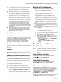
See Fig. 1 for Software Revision Level number location on
the label (located on the rear of the relay module).

EC7830A, RM7830A, EC7850A, RM7850A 7800 SERIES RELAY MODULES
32-00198—03 4
Any relay module in the new 2000 series will only be able
to be installed on subbase Q7800A2005/U,
Q7800B2003/U and will not be backward compatible with
any Q7800A1003/U and Q7800A1005/U subbases
already installed in the field.
Fig. 1. Software revision location.
IMPORTANT
Make sure to check the relay model number and
the software revision level on the relay.
5. If you attempt to place a 2000 series relay on a non-
compatible 1000 series subbase, you will receive an
error code of 101. This indicates that you must a)
change out the subbase to a Q7800A2003/U or
Q7800A2005/U or b) choose a compatible 1000
series relay module
Wiring Subbase
WARNING
Electrical Shock Hazard or Equipment Damage
Hazard.
Can cause sever injury, death or equipment
damage.
Disconnect the power supply before beginning
installation. More than one disconnect may be
involved.
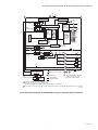
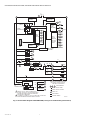
The internal block diagram of the EC/RM7830A is shown
in Fig. 2 and the internal block diagram of the
EC/RM7850A is shown in Fig. 3.
1. For subbase wiring and sequence charts, refer to Fig.
3 and 4.
2. For proper remote wiring of the KDM, refer to the
Specifications for the 2-line VFD KDM (65-0090),
the 4-line LCD KDM (32-00110), Data ControlBus
Module™ (65-0091) or Extension Cable Assembly
(65-0131).
3. Disconnect the power supply from the main discon-
nect before beginning installation to prevent electri-
cal shock and equipment damage. More than one
disconnect can be required.
4. All wiring must comply with all applicable electrical
codes, ordinances and regulations. Wiring, where
required, must comply with NEC Class 1 (Line Volt-
age) wiring.
5. For recommended wire size and type, see Table 1.
6. Recommended wire routing of leadwires:
a. Do not run high voltage ignition transformer
wires in the same conduit with the flame
detector, Data ControlBus™ Module, or Remote
Reset Module wiring.
b. Do not route flame detector, Data ControlBus™
Module, or Remote Reset Module leadwires in
conduit with line voltage circuits.
c. Enclose flame detector leadwires without armor
cable in metal cable or conduit.
d. Follow directions in flame detector, Data Control-
Bus™ Module, or Remote Reset Module Instruc-
tions.
7. For recommended grounding practices, see Table 2.
8. The KDM is powered from a low voltage, energy lim-
ited source. Mount the KDM outside of a control
panel when it is protected from mechanical damage.
IMPORTANT
A 13 Vdc power supply must be used any time
more than one KDM is used. A maximum of two
KDM, Data ControlBus™ Modules or S7810B
Multi-Drop Switch Modules are allowed in any
combination.
9. Maximum wire lengths:
a. EC/RM7830A and EC/RM7850A leadwires: The
maximum leadwire length is 300 feet (91 meters)
to terminal inputs (Control, Running/Lockout
Interlock).
b. Flame Detector leadwires: The maximum flame
sensor leadwire length is limited by the flame
signal strength.
c. Remote Reset leadwires: The maximum length of
wire is 1000 feet (305 meters) to a Remote Reset
pushbutton.
d. Data ControlBus™ Module: The maximum Data
ControlBus™ Module cable length depends on
the number of system modules connected, the
noise conditions and the cable used. The maxi-
mum length of all Data ControlBus™ Module
interconnecting wire is 4000 feet (1219 meters).
10. Be sure loads do not exceed the terminal ratings.
Refer to the label on the relay module or to the
terminal ratings in Tables 3A, 3B, 3C and 3D.

EC7830A, RM7830A, EC7850A, RM7850A 7800 SERIES RELAY MODULES
532-00198—03
Fig. 2. Internal block diagram of EC/RM7830A (see Fig. 4 for detailed wiring instructions).
L1
HOT N
1
52
CONFIGURATION
JUMPERS
PLUG-IN PURGE
TIMER CARD
F
G
22
PLUG-IN
FLAME
AMPLIFIER
MICROCOMPUTER
RUN/TEST
SWITCH
RESET
PUSHBUTTON
FLAME SIGNAL
TEST
JACK
RELAY
DRIVE
CIRCUIT
1K
2K
3K
4K
5K
6K
7K
CONTROL
POWER
POWER SUPPLY
17
RELAY
STATUS
FEEDBACK
AND LINE
VOLTAGE
INPUTS
10
8
21
9
4
3
OPTIONAL KEYBOARD
DISPLAY MODULE
RS485
16
1K1
2K2 5K1
4K1
7K1
2K1
PV1
PV2
MV
3K1
6K1
7
ES2
3K2
SAFETY RELAY
CIRCUIT
20 6
FAN
AL
IGN
AL
DDL
REMOTE
RESET
INDICATES FEEDBACK SENSING
OF RELAY CONTACT STATUS
AND LINE VOLTAGE INPUTS
RELAY CONTACT OPEN
INTERNAL WIRING
FIELD WIRING
RELAY COIL
RELAY CONTACT CLOSED
DDL
COMMUNICATIONS
1
2
3
5
USER TERMINALS
1
2
2
RM7830A: 120 VAC, 50/60 Hz POWER SUPPLY
EC7830A: 220-240 VAC, 50/60 Hz POWER SUPPLY.
PROVIDE DISCONNECT MAINS AND OVERLOAD PROTECTION AS REQUIRED.
TO CONNECT L1 DIRECTLY TO LOS, AT LEAST ONE CONTROLLED SHUTDOWN MUST BE PROVIDED EVERY 24 HOURS.
M15183B
STATUS
LEDS
RTLOS
LD2
SHUTTER
FG... 22

EC7830A, RM7830A, EC7850A, RM7850A 7800 SERIES RELAY MODULES
32-00198—03 6
Fig. 3. Internal block diagram of EC/RM7850A (see Fig. 5 for detailed wiring instructions).
L1
HOT N
1
42
19
CONFIGURATION
JUMPERS
PLUG-IN PURGE
TIMER CARD
F
G
22
PLUG-IN
FLAME
AMPLIFIER
MICROCOMPUTER
RUN/TEST
SWITCH
RESET
PUSHBUTTON
FLAME SIGNAL TEST
JACK
RELAY
DRIVE
CIRCUIT
1K
2K
3K
4K
5K
6K
7K
8K
9K
CONTROL
POWER
POWER SUPPLY
18
17
RELAY
STATUS
FEEDBACK
AND LINE
VOLTAGE
INPUTS
10
8
21
9
5
3
OPTIONAL KEYBOARD
DISPLAY MODULE
RS485
16
1K1
2K2 5K1
4K1
7K1
2K1
PV1
PV2
MV
3K1
6K1
7
ES1
ES3
ES2
3K2
SAFETY RELAY
CIRCUIT
20 6
FAN
AL
IGN
AL
DDL 13
15
14
12
HIGH FIRE
COMMON
LOW FIRE
MODULATE
REMOTE
RESET
8K1
8K2
9K2 9K1
INDICATES FEEDBACK SENSING
OF RELAY CONTACT STATUS
AND LINE VOLTAGE INPUTS
RELAY CONTACT OPEN
INTERNAL WIRING
FIELD WIRING
RELAY COIL
RELAY CONTACT CLOSED
DDL
COMMUNICATIONS
1
2
3
5USER TERMINALS
1
2
2
RM7850A: 120 VAC, 50/60 Hz POWER SUPPLY
EC7850A: 220-240 VAC, 50/60 Hz POWER SUPPLY
PROVIDE DISCONNECT MAINS AND OVERLOAD
PROTECTION AS REQUIRED.
TO CONNECT L1 DIRECTLY TO LOS, AT LEAST ONE CONTROLLED
SHUTDOWN MUST BE PROVIDED EVERY 24 HOURS.
M15184B
STATUS
LEDS
RTLOS
LD2
SHUTTER
FG
... 22

EC7830A, RM7830A, EC7850A, RM7850A 7800 SERIES RELAY MODULES
732-00198—03
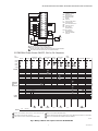
Fig. 4. Wiring subbase and sequence chart for EC/RM7830A.
L1
N
1
G12
N13
314
415
516
617
718
819
(L1)
920
10 21
F22
AL
FAN
RT
LD2
PV1
MV
IGN
ES2
LOS
PV2
FLAME
DETECTOR
1RM7830A: 12O VAC, 50/60 Hz POWER SUPPLY
EC7830A: 220-240 VAC, 50/60 Hz POWER SUPPLY
PROVIDE DISCONNECT MAINS AND OVERLOAD PROTECTION AS REQUIRED.
SEE FLAME DETECTOR INSTRUCTIONS FOR CORRECT WIRING.
LEGEND
ALARM
(NORMALLY OPEN)
PREIGNITION
INTERLOCK INPUT
BURNER/BLOWER
MOTOR
IGNITION
LINE VOLTAGE SUPPLY
LOCKOUT INPUT
AIRFLOW SWITCH INPUT
MAIN FUEL VALVE
PILOT VALVE 1
(INTERRUPTED)
PILOT VALVE 2
(INTERMITTENT)
LIMITS AND BURNER
CONTROL
AL
ES2
FAN
IGN
L1
LOS
LD2
MV
PV1
Q7800
2
2
INITIATE
POWER
PILOT
FLAME
MAIN
ALARM
STANDBY RUN STANDBY
PRE
IGNITION
PILOT
STABIL.
MAIN
STABIL.
IGNITION
BURNER
POSTPURGE
MAIN VALVE
LIMITS AND BURNER CONTROL CLOSED
LOCKOUT INPUT
10 sec
AIRFLOW SWITCH CHECK
PILOT VALVE
V2
PREIGNITION INTERLOCK
OPTIONS
SAFE START CHECK FLAME PROVING
3 sec 5 sec 5 sec
1 IF ON AT CALL FOR HEAT, HOLD (120 sec). LOCK OUT IF STILL ON.
3 or 5 sec 3 or 5 sec
SAFE START CHECK
IF OFF AFTER 10 SEC OF FAN, LOCK OUT.
2
2, 15 or 30 sec
3
4
5
TAKE LOCKOUT ACTION, CONTINUE POSTPURGE TIMING.
SELECT VIA ST7800A PURGE TIMER CARD.
456
SELECT VIA CONFIGURATION JUMPERS OR MODEL NUMBERS.
AFS CHK
1
2 sec
AFS CHK
AFS CHK
DUE TO ONE EXTRA SECOND FOR SAFETY RELAY TEST, TIMING CAN VARY FROM 3 TO 4 SECONDS.
6
LED
DISPLAY "PREPURGE"
WAITING
FIRST SAFETY
TIME
MAIN TRIAL
TIME
OPERATING
CONTROLS
AND
INTERLOCKS
FLAME
SIGNAL
EC/RM7830A Power Burner ON/OFF, GAS or OIL Sequence
2
3
66
M15185B
PV2
RT
8
21
9
6
20
7
10
17
BURNER/BLOWER MOTOR 4

EC7830A, RM7830A, EC7850A, RM7850A 7800 SERIES RELAY MODULES
32-00198—03 8
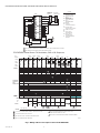
Fig. 5. Wiring subbase and sequence chart for EC/RM7850A.
L1
N
1
G12
N13
314
415
516
617
718
819
(L1)
920
10 21
F22
AL
FAN
RT
LD2
PV1
MV
IGN
B
R
W
B
R
W
HIGH FIRE
COMMON
MODULATE
LOW FIRE
ES2
ES1
ES3
LOS
PV2
FLAME
DETECTOR
1120 VAC, 50/60 HZ POWER SUPPLY, RM7850A; 220-240 VAC, 50/60 HZ POWER SUPPLY, EC7850A.
SEE FLAME DETECTOR INSTRUCTIONS FOR CORRECT WIRING.
LEGEND
ALARM
(NORMALLY OPEN)
LOW FIRE SWITCH
INPUT
PREIGNITION
INTERLOCK INPUT
HIGH FIRE SWITCH
INPUT
BURNER/BLOWER
MOTOR
IGNITION
LINE VOLTAGE SUPPLY
LOCKOUT INPUT
AIRFLOW SWITCH INPUT
MAIN FUEL VALVE
PILOT VALVE 1
(INTERRUPTED)
PILOT VALVE 2
(INTERMITTENT)
LIMITS AND BURNER
CONTROL
AL
ES1
ES2
ES3
FAN
IGN
L1
LOS
LD2
MV
PV1
SERIES 90
FIRING RATE
MOTOR
Q7800
SERIES 90
CONTROLLER
2
2
INITIATE
POWER
PILOT
FLAME
MAIN
ALARM
STANDBY RUN STANDBY
PURGE
OR
WAITING
PRE
IGNITION
PILOT
STABIL.
MAIN
STABIL.
IGNITION
BURNER
POSTPURGE
MAIN VALVE
LIMITS AND BURNER CONTROL CLOSED
LOCKOUT INPUT
10 sec
AIRFLOW SWITCH CHECK
PILOT VALVE
V2
PREIGNITION INTERLOCK
OPTIONS
SAFE START CHECK FLAME PROVING
3 sec 5 sec 5 sec
1 IF ON AT CALL FOR HEAT, HOLD (120 SEC). LOCK OUT IF STILL ON.
IF OFF AFTER 10 SEC OF FAN, LOCK OUT.
TAKE LOCKOUT ACTION. CONTINUE POSTPURGE TIMING.
SELECT VIA ST7800A PURGE TIMER CARD.
3 or 5 sec 3 or 5 sec
SAFE START CHECK
2
MODHF
LF
LF
HF
MOD
MOTOR
HF Sw LF Switch
2, 15 or 30 sec
3
4
5
456
DUE TO ONE EXTRA SECOND FOR SAFETY RELAY TEST,
TIMING CAN VARY FROM 3 TO 4 SEC.
SELECTION VIA CONFIGURATION JUMPERS OR MODEL NUMBERS.
AFS CHK
1
2 sec
AFS CHK
AFS CHK
6
LED
DISPLAY
DRIVE
TO HIGH
FIRE
DRIVE
TO LOW
FIRE
FIRST
SAFETY
TIME
MAIN
TRIAL
TIME
OPERATING
CONTROLS
AND
INTERLOCKS
FLAME
SIGNAL
EC/RM7850A Power Burner Full Modulation, GAS or OIL Sequence
2
3
6 6
M23304
10
BURNER/BLOWER MOTOR 5
8
21
9
6
20
7
1819
RT
PV2
17
7

EC7830A, RM7830A, EC7850A, RM7850A 7800 SERIES RELAY MODULES
932-00198—03
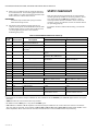
Table 1. Recommended Wire Sizes and Part Numbers.
a The KDM, Data ControlBus™ Module (for remote mounting or communications) or Communication Interface Control-
Bus™ Module must be wired in a daisy chain configuration, (1(a)-1(a), 2(b)-2(b), 3(c)-3(c)). The order of interconnection
of all the devices listed above is not important. Be aware that modules on the closest and farthest end of the daisy chain
configuration string require a 120 ohm (1/4 watt minimum) resistor termination across terminals 1 and 2 of the electri-
cal connectors for connections over 100 feet (30.5 meters).
Table 2. Recommended Grounding Practices.
Final Wiring Check
1. Check the power supply circuit. The voltage and fre-
quency tolerance must match those of the relay
module. (A separate power supply circuit can be
required for the relay module.) Add the required dis-
connect means and overload protection.
2. Check all wiring circuits and complete the Static
Checkout in Table 5 or 6 before installing the relay
module on the subbase.
3. Install the relay module.
4. Restore power to the panel.
Mounting EC/RM7830A;
EC/RM7850A Relay Module
1. Mount the relay module vertically on the Q7800
Subbase, or mount horizontally with the knife blade
terminals pointing down. Select a location on a wall,
burner or electrical panel to mount the subbase. For
all CE device installations the subbase must be
mounted inside of an approved electrical cabinet
where access is restricted.
2. Be sure to allow adequate clearance for servicing,
installation and removal of the relay module, KDM,
flame amplifier, flame amplifier signal voltage
probes, electrical signal voltage probes and
electrical connections.
a. Allow an additional 2 in. (51 mm) below the relay
module for the flame amplifier mounting.
b. Allow an optional 3 in. (76 mm) minimum on
both sides of the relay module for electrical sig-
nal voltage probes.
Application Recommended Wire Size Recommended Part Numbers
Line Voltage Terminals 14, 16, or 18 AWG (0.75, 1.5 or 2.5 mm2) copper
conductor, 600 volt insulation, moisture-resistant
wire.
TTW60C, THW75C, THHN90C.
Keyboard Display
Module KDMa22 AWG (0.34 mm2) two-wire twisted pair with
ground, or five-wire.
Belden 8723 shielded cable or
equivalent.
Data ControlBus™
Module
Remote Reset Module 22 AWG (0.34 mm2) two-wire twisted pair, insulated
for low voltage.
—
Communications
Interface ControlBus™
Module
22 AWG (0.34 mm2) two-wire twisted pair with
ground.
Belden 8723 shielded cable or
equivalent.
13 Vdc full wave rectified
transformer power input 18 AWG (0.75 mm2) wire insulated for voltages and
temperatures for given application.
TTW60C, THW75C, THHN90C.
Ground Type Recommended Practice
Earth ground (subbase and relay
module)
1. Use to provide a connection between the subbase and the control panel of
the equipment. Earth ground must be capable of conducting enough cur-
rent to blow the 15A fuse (or breaker) in the event of an internal short circuit.
2. Use wide straps or brackets to provide minimum-length, maximum-surface
area ground conductors. If a leadwire must be used, use 14 AWG (2.5 mm2)
copper wire.
3. Make sure that mechanically tightened joints along the ground path are free
of nonconductive coatings and protected against corrosion on mating sur-
faces.
Signal Ground (KDM, Data
ControlBus™ Module,
Communications Interface
ControlBus™ Module)
Use the shield of the signal wire to ground the device to the signal ground terminal
3(c) of each device. Connect the shield at both ends of the daisy chain to earth
ground.

EC7830A, RM7830A, EC7850A, RM7850A 7800 SERIES RELAY MODULES
32-00198—03 10
3. Make sure no subbase wiring is projecting beyond
the terminal blocks. Tuck in wiring against the back
of the subbase so it does not interfere with the knife
blade terminals or bifurcated contacts.
IMPORTANT
Install the relay module with a plug-in motion
rather than a hinge action.
4. Mount the relay module by aligning the four L
shaped corner guides and knife blade terminals with
the bifurcated contacts on the wiring subbase and
securely tightening the two screws without
deforming the plastic.
STATIC CHECKOUT
After checking all wiring, perform this checkout before
installing the relay module on the wiring subbase. These
tests verify that the Q7800 Wiring Subbase is wired
correctly and the external controllers, limits, interlocks,
actuators, valves, transformers, motors and other devices
are operating properly.
For further checkout and troubleshooting, see form 65-
0229.
aSee Table 2.
bHoneywell has tested this output at 9.8A at PF = 0.5, 58.8A inrush for 100,000 cycles (EN298 approval does not require
this test).
c2000 VA maximum connected load to relay module.
d1A, 10A inrush for 5000 cycles; carry 5A for 250,000 cycles.
e220/240 Vac to 120 Vac, 10 VA stepdown transformer (not provided) must be used to drive the shutter. Transformer
does not apply to UV flame sensor models C7061A1020, C7061A1079 and C7061F1003 (combined with R7861-series
flame amplifiers), which have internal selectable terminal block to connect 230V shutter output directly.
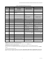
Table 3. EC7830A/RM7830A Terminal Ratings.
Termina
l No. Abbreviation Description
Ratings
RM7830A (120 Vac) EC7830A (220/230/240 Vac)
G— Flame Sensor Grounda——
Earth G — Earth Grounda——
N — Line Voltage Common
(Neutral)
——
3 AL Alarm (Normally Open) 1A, 10A inrush for 5000
cycles.
1A, 10A inrush for 5000 cycles.
4 FAN Burner/Blower Motor 4A at PF = 0.5, 20A inrush.b4A at PF = 0.5, 20A inrush.
5 L1 Line Voltage Supply (L1) 120 Vac(+10%/-15%), 50/60
Hz (±10%).c
220 to 240 Vac (+10%/-15%),
50/60 Hz (±10%).c
6 RT Limits and Burner Control 1 mA 1 mA maximum
7 LD2 Airflow Switch Input 5A. 5A.
8 PV1 Pilot Valve 1 (Interrupted) 4A at PF = 0.5, 20A inrush. 4A at PF = 0.5, 20A inrush.
9 MV Main Fuel Valve 4A at PF = 0.5, 20A inrush. 4A at PF = 0.5, 20A inrush.
10 IGN Ignition 2A at PF = 0.2. 2A at PF = 0.2.
F (11) — Flame Signal 60 to 220 Vac, current limited. 60 to 220 Vac, current limited.
12 to 15 Not Used.
16 — Control Voltage 120 Vac (+10%/-15%).d220 to 240 Vac (+10%/-15%).d
17 ES2 Preignition Interlock Input 1 mA. 1 mA.d
18 to 19 Not Used.
20 LOS Lockout Input. 1 mA. 1 mA.
21 PV2 Pilot Valve 2 (intermittent) 4A at PF = 0.5, 20A inrush. 4A at PF = 0.5, 20A inrush.
22 SHTR Shutter Shutter drive for dynamic self-
check flame sensor.
Shutter drive for dynamic
self-check flame sensor.e

EC7830A, RM7830A, EC7850A, RM7850A 7800 SERIES RELAY MODULES
11 32-00198—03
aSee Table 2.
b2000 VA maximum connected load to relay module.
cHoneywell has tested this output at 9.8A at PF = 0.5, 58.8A inrush for 100,000 cycles
(EN298 approval does not require this test).
dTotal load current, excluding Burner/Boiler Motor and Firing Rate Outputs cannot exceed 5A, 25A inrush.
eTotal load current, excluding Burner/Boiler Motor and Firing Rate Outputs cannot exceed 5A, 25A inrush for 250,000
cycles.
fCan also be 24 Vac, 3A at PF = 0.5.
gTransformer does not apply to UV flame sensor models C7061A1020, C7061A1079 and C7061F1003 (combined with
R7861-series flame amplifiers), which have internal selectable terminal block to connect 230V shutter output directly.
Table 4. EC7850A/RM7850A Terminal Ratings.
Terminal
No. Abbreviation Description RM7850A (120 Vac) EC7850A (220 to 240 Vac)
G— Flame Sensor Ground.a——
Earth G — Earth Ground.a——
N — Line Voltage Common
(Neutral)
——
3 AL Alarm (Normally Open) 1A, 10A inrush for 5000
cycles.
1A, 10A inrush for 5000
cycles.
4 L1 Line Voltage Supply (L1) 120 Vac (+10%/-15%),
50/60 Hz (±10%).b
220 to 240 Vac (+10%/-
15%), 50/60 Hz (±10%).b
5 FAN Burner/Blower Motor 4A at PF = 0.5, 20A inrush.c4A at PF = 0.5, 20A inrush.
6 RT Limits and Burner Control 1 mA. 1 mA.
7 LD2 Airflow Switch Input 5A. 5A.
8 PV1 Pilot Valve 1 (Interrupted) 4A at PF = 0.5, 20A inrush.d4A at PF = 0.5, 20A inrush.e
9MV Main Fuel Valve 4A at PF = 0.5, 20A inrush.d4A at PF = 0.5, 20A inrush.e
10 IGN Ignition 2A at PF = 0.2. 2A at PF = 0.2.
F (11) — Flame Signal 60 to 220 Vac, current
limited.
136 to 220 Vac, current
limited.
12 HI Firing Rate High Fire 0.5A at PF = 0.5.f0.5A at PF = 0.5.f
13 COM Firing Rate Common 0.5A at PF = 0.5.0.5A at PF = 0.5.f
14 MOD Firing Rate Modulate 0.5A at PF = 0.5.f0.5A at PF = 0.5.f
15 LO Firing Rate Low Fire 0.5A at PF = 0.5.f0.5A at PF = 0.5.f
16 — Alarm (Normally Closed) 1A, 10A inrush for 5000
cycles; carry 5A for 250,000
cycles.
1A, 10A inrush for 5000
cycles; carry 5A for 250,000
cycles.
17 ES2 Preignition Interlock Input 1 mA. 1 mA.
18 ES1 Low Fire Switch Input (SPP) 1 mA. 1 mA.
19 ES3 High Fire Switch Input (PPP) 1 mA. 1 mA.
20 LOS Lockout Input 1 mA. 1 mA.
21 PV2 Pilot Valve 2 (Intermittent) 4A at PF = 0.5, 20A inrush.d4A at PF = 0.5, 20A inrush.e
22 SHTR Shutter Shutter drive for dynamic
self-check flame sensor.
Shutter drive for dynamic
self-check flame sensor.g

EC7830A, RM7830A, EC7850A, RM7850A 7800 SERIES RELAY MODULES
32-00198—03 12
WARNING
Fire or Explosion Hazard.
Can cause severe injury, death, or property
damage.
Close all manual fuel shutoff valves before starting
this test to prevent an explosion.
WARNING
Electrical Shock Hazard.
Can cause severe injury, death, or property
damage.
Use extreme care when testing the system. Line
voltage is present on most terminal connections
when power is on. Ensure proper selection of
configuration jumpers before starting the burner
operation.
CAUTION
Equipment Damage Hazard.
Improper testing can cause equipment damage.
Do not perform a dielectric test with the relay
module installed. Internal surge protectors break
down and conduct a current. This can cause the
relay module to fail the dielectric test or destroy the
internal lightning and high current protection.
1. Open the master switch before installing or remov-
ing a jumper on the subbase.
2. Before continuing to the next test, be sure to remove
test jumper(s) used in the previous test.
3. Replace all limits and interlocks that are not operat-
ing properly. Do not bypass limits and interlocks.
Equipment Recommended
Voltmeter (1M ohm/volt minimum sensitivity) set on the 0
to 300 Vac scale and two jumper wires, No. 14 AWG (2.5
mm2) wire, insulated, 12 in. (304.8 mm) long with
insulated alligator clips at both ends.
General Instructions
1. Perform all applicable tests listed in the Static
Checkout, Table 4 or 5, in the order listed.
2. Make sure all manual fuel shutoff valves are closed.
3. For each test, open the master switch and install the
jumper wire(s) between the subbase wiring termi-
nals listed in the Test Jumpers column.
4. Close the master switch before observing operation.
5. Read the voltage between the subbase wiring termi-
nals listed in the Voltmeter column.
6. If there is no voltage or the operation is abnormal,
check the circuits and external devices as described
in the last column.
7. Check all wiring for correct connections, tight termi-
nal screws, correct wire, and proper wiring tech-
niques.
8. Replace all damaged or incorrectly sized wires.
9. Replace faulty controllers, limits, interlocks, actua-
tors, valves, transformers, motors and other devices,
as required.
10. Make sure normal operation is obtained for each
required test before continuing the checkout.
11. After completing each test, be sure to open the mas-
ter switch and remove the test jumper(s).
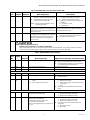
Table 5. EC/RM7830A Static Checkout.
Test
No.
Test
Jumpers Voltmeter Normal Operation
If Operation is Abnormal, Check the Items
Listed Below
1 None 5-L2 Line voltage at terminal 5. 1. Master switch.
2. Power connected to the master switch.
3. Overload protection (fuse, circuit
breaker, etc.) opened the power line.
2 None 17-L2 Line voltage at terminal 17. Preignition interlocks.
3 5-16 — Alarm (if used) turns on. Alarm.
NOTE: Disconnect horn at this time (if used).
4 5-16 2-20 Line voltage at terminal 20. Limits in Lockout Circuit.
5 5-16 2-6 Line voltage at terminal 6. 1. Recycle limits.
2. Burner control.
65-16
5-4
2-7 1. Fan (Burner Motor or Blower)
starts.
2. Line voltage at terminal 7.
1. Fan circuit.
a. Manual Fan Switch.
b. Fan power supply, overload protec-
tion and starter.
c. Fan.
2. Running Limits or Airflow Switch (LD2
input).
NOTE: Remove jumpers and reconnect alarm (if used).
7 5-10 — Ignition spark (if ignition transformer is
connected to terminal 10).
1. Watch for spark or listen for buzz.
a. Ignition electrodes are clean.
b. Ignition transformer is okay.

EC7830A, RM7830A, EC7850A, RM7850A 7800 SERIES RELAY MODULES
13 32-00198—03
85-8 — 1. Ignition spark (if ignition trans-
former is connected to terminal 8).
2. Automatic pilot valve opens (if
connected to terminal 8).
NOTE: Refer to wiring diagram of sys-
tem being tested.
1. Watch for spark or listen for buzz.
a. Ignition electrodes are clean.
b. Ignition transformer is okay.
2. Listen for click of fee head of valve for
activation.
a. Actuator, if used.
b. Pilot valve.
9 5-21 — Same as test no. 8 for connections to
terminal 8. If using direct spark ignition,
check the first stage fuel valve(s) instead
of the pilot valve.
Same as test no. 8. If using direct spark
ignition, check the first stage fuel valve(s)
instead of the pilot valve.
10 5-9 — Automatic fuel valve(s) open(s).
If using direct spark ignition on a model
with intermittent pilot on terminal 21,
check the optional second stage fuel
valve, if used.
1. Listen for and observe operation of the
main fuel valve(s) and actuator(s).
2. Valve(s) and actuator(s).
Final
CAUTION
Equipment Damage Hazard.
Failure to remove jumpers can damage equipment.
After completing these tests, open the master switch and remove ALL test jumpers from the subbase
terminals. Then remove bypass jumpers from the low fuel pressure limits (if used).
Table 6. EC/RM7850A Static Checkout.
Test
No.
Test
Jumper
s Voltmeter Normal Operation If Operation is Abnormal, Check These Items
1 None 4-2 Line voltage at terminal 4. 1. Master switch.
2. Power connected to the master switch.
3. Overload protection (fuse, circuit breaker,
etc.) did not open the power line.
2 None 17-2 Line voltage at terminal 17. Preignition interlocks.
3 4-16 — Alarm (if used) turns on. Alarm.
NOTE: Disconnect horn at this time (if used).
4 4-16 2-20 Line voltage at terminal 20. Limits in Lockout Circuit.
5 4-16 2-6 Line voltage at terminal 6. 1. Recycle limits.
2. Burner control.
64-16
5-4
2-7 1. Fan (Burner Motor or Blower)
starts.
2. Line voltage at terminal 7.
1. Fan circuit.
a. Manual fan switch.
b. Fan power supply, overload protection
and starter.
c. Fan.
2. Running limits of Airflow Switch (LD2)
input.
NOTE: Remove jumpers and re-connect alarm (if used).
7 4-10 — Ignition spark (if ignition transformer is
connected to terminal 10).
1. Watch for spark or listen for buzz.
a. Ignition electrodes are clean.
b. Ignition transformer is okay.
8 4-8 — Ignition spark (if ignition transformer is
connected to terminal 8).
Automatic pilot valve opens (if
connected to terminal 8).
Refer to wiring diagram of system being
tested.
1. Watch for spark or listen for buzz.
a. Ignition electrodes are clean.
b. Ignition transformer is okay.
2. Listen for click of fee head of valve for
activation.
a. Actuator, if used.
b. Pilot valve.
Table 5. EC/RM7830A Static Checkout. (Continued)
Test
No.
Test
Jumpers Voltmeter Normal Operation
If Operation is Abnormal, Check the Items
Listed Below

EC7830A, RM7830A, EC7850A, RM7850A 7800 SERIES RELAY MODULES
32-00198—03 14
WARNING
Explosion hazard.
Can cause serious injury or death.
Be sure all manual fuel shutoff valves are closed.
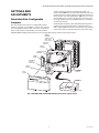
Mounting Other System
Components (Fig. 6)
Refer to the applicable specifications for mounting other
system components.
PRINCIPAL TECHNICAL
FEATURES
The EC/RM7830A or EC/RM7850A Relay Module provide
all customary flame safeguard functions as well as
significant advancements in safety, annunciation, and
system diagnostics.
Safety Shutdown (Lockout) Occurs
If:
1. INITIATE Period
a. Purge card is not installed or removed.
b. Purge card is defective.
c. Configuration jumpers were changed (after 200
hours of operation).
d. AC line power errors, see Operation.
e. Four minute INITIATE period is exceeded.
2. STANDBY Period
a. Flame signal is present after 40 seconds.
b. Preignition Interlock is open an accumulative
time of 30 seconds.
c. Airflow Switch feature is enabled and the Airflow
Switch is closed for 120 seconds with Limits and
Burner Control closed.
d. Ignition/pilot valve/intermittent pilot valve ter-
minal is energized.
e. Main valve terminal is energized.
f. Internal system fault.
g. Purge card is not installed or removed.
h. Purge card is defective.
i. Lockout Input opens during STANDBY.
3. PURGE Period
a. Preignition Interlock opens anytime during
purge.
b. Flame signal detected during purge.
9 4-21 — Same test as no. 4 for connections to
terminal 8. If using direct spark ignition,
check the first stage fuel valve(s)
instead of the pilot valve.
Same as test no. 4. If using direct spark ignition,
check the first stage fuel valve(s) instead of the
pilot valve.
10 4-9 — Automatic main fuel valve(s) open(s). If
using direct spark ignition on a model
with intermittent pilot on terminal 21,
check the optional second stage fuel
valve, if used.
1. Listen for and observe operation of the
main fuel valve(s) and actuator(s).
2. Valve(s) and actuator(s).
11 12-13 18-L2 Voltmeter reads line voltage, then zero
volts on terminal 18 after motor starts
driving open.
1. Low Fire Start Switch.
2. Firing rate motor and transformer.
12 12-13 19-L2 Firing rate motor drives open; line
voltage at terminal 19 after motor is in
High Fire position.
1. High Fire Purge Switch.
2. Firing rate motor and transformer.
13 14-13 19-L2 Firing rate motor drives closed; zero
volts at terminal 19 after motor starts
driving closed.
1. Low Fire Start Switch.
2. Firing rate motor and transformer.
14 15-13 — 1. Raise setpoint of Series 90
controller—firing rate motor
should drive toward open.
2. Lower setpoint of Series 90
controller—firing rate motor
should drive toward closed.
1. Series 90 controller.
2. Firing rate motor and transformer.
Final
CAUTION
Equipment Damage Hazard.
Failure to remove jumpers can damage equipment.
After completing these tests, open the master switch and remove all test jumpers from the subbase
terminals. Also, remove bypass jumpers from the low fuel pressure limits (if used).
Table 6. EC/RM7850A Static Checkout. (Continued)
Test
No.
Test
Jumper
s Voltmeter Normal Operation If Operation is Abnormal, Check These Items

EC7830A, RM7830A, EC7850A, RM7850A 7800 SERIES RELAY MODULES
15 32-00198—03
c. High Fire Switch fails to close within five minutes
after the firing rate motor is commanded to drive
to high fire position at start of purge
(EC/RM7850A).
d. Low Fire Switch fails to close within five minutes,
after firing rate motor is commanded to drive to
low fire position at end of purge (EC/RM7850A).
e. Airflow Switch Input does not close within 10
seconds.
f. If Airflow Switch is disabled, there is no jumper
between terminals 6 and 7.
g. Airflow Switch opens during PURGE.
h. Lockout Input opens during purge.
i. Ignition/pilot valve/intermittent pilot valve ter-
minal is energized.
j. Main valve terminal is energized.
k. Internal system fault.
l. Purge card is removed.
m. Purge card is defective.
4. PREIGNITION
a. Lockout Input opens during PREIGNITION.
b. Airflow Switch opens during PREIGNITION.
c. Preignition Interlock opens during PREIGNI-
TION.
d. Flame signal detected during PREIGNITION.
e. Ignition terminal is not energized.
f. Pilot valve/intermittent pilot valve terminal is
energized.
g. Main valve terminal is energized.
h. Internal system fault.
i. Purge card is removed.
j. Purge card is defective.
5. SAFETY 1 PERIOD
a. Lockout Input opens during SAFETY 1.
b. Airflow Switch opens during SAFETY 1.
c. Low Fire Switch opens (EC/RM7850A).
d. No flame is present at the end of SAFETY 1.
e. Ignition terminal is not energized.
f. Pilot valve/intermittent pilot valve terminal is not
energized.
g. Main valve terminal is energized.
h. Internal system fault.
i. Purge card is removed.
j. Purge card is defective.
6. PILOT STAB. PERIOD
a. Lockout Input opens during PILOT STAB.
b. Airflow Switch opens during PILOT STAB.
c. Low Fire Switch opens (EC/RM7850A).
d. No flame is present.
e. Ignition terminal is energized.
f. Pilot valve/intermittent pilot valve terminal is not
energized.
g. Main valve terminal is energized.
h. Internal system fault.
i. Purge card is removed.
j. Purge card is defective.
7. MAIN TRIAL PERIOD
a. Lockout Input opens during MAIN TRIAL.
b. irflow Switch opens during MAIN TRIAL.
c. Low Fire Switch opens (EC/RM7850A).
d. No flame is present.
e. Ignition terminal is energized.
f. Pilot valve/intermittent pilot valve terminal is not
energized.
g. Pilot valve is energized during MAIN TRIAL
stabilization.
h. Main valve terminal is not energized.
i. Internal system fault.
j. Purge card is removed.
k. Purge card is defective.
8. RUN Period.
a. No flame is present.
b. Lockout Input opens.
c. Ignition/interrupted pilot valve terminal is ener-
gized.
d. Main valve terminal is not energized.
e. Internal system fault.
f. Purge card is removed.
g. urge card is defective.
h. Airflow Switch Input opens.
9. POSTPURGE Period.
a. Ignition/pilot valve/intermittent pilot valve ter-
minal is energized.
b. Main valve terminal is energized.
c. Internal system fault.
d. Purge card is removed.
e. Purge card is defective.
OPERATION
Sequence of Operation
The relay modules have the operating sequences listed
below; see Fig. 3 and 4. The relay module LED provide
positive visual indication of the program sequence:
POWER, PILOT, FLAME, MAIN and ALARM.
Initiate
The relay module enters the INITIATE sequence when the
relay module is initially powered. The relay module can
also enter the INITIATE sequence if the relay module
verifies voltage fluctuations of +10/-15% or frequency
fluctuations of ±10% during any part of the operating
sequence. The INITIATE sequence lasts for two seconds
unless the voltage or frequency tolerances are not met.
When not met, a hold condition is initiated and displayed
on the optional KDM for at least five seconds; when met,
the INITIATE sequence restarts. If the condition is not
corrected and the hold condition exists for four minutes,
the relay module locks out. Causes for hold conditions in
the INITIATE sequence:
a. AC line dropout detection.
b. AC line noise that can prevent a sufficient
reading of the line voltage inputs.
c. Low line voltage brownouts.
The INITIATE sequence also delays the burner motor
starter from being energized and de-energized from an
intermittent AC line input or control input.
Standby
The relay module is ready to start an operating sequence
when the operating control input determines a call for
heat is present. The burner switch, limits, operating limit
control and all microcomputer-monitored circuits must be
in the correct state for the relay module to continue into
the PURGE sequence.

EC7830A, RM7830A, EC7850A, RM7850A 7800 SERIES RELAY MODULES
32-00198—03 16
Normal Start-Up Purge
The relay module provides PURGE timing selectable from
two seconds to thirty minutes with power applied and the
operating control indicating a call for heat.
1. The Preignition Interlocks, Limits and Burner Con-
trol, Run/Test Switch, Airflow Switch Input, Lockout
Input, and all microcomputer-monitored circuits
must also be in the correct operating state.
2. The blower motor output, terminal 5, is powered to
start the PURGE sequence. The firing rate motor is
driven to the high fire position (EC/RM7850A). The
PURGE timing does not begin until the Airflow
Switch Input and High Fire Switch (EC/RM7850A)
are both closed.
3. The Preignition Interlock Input must remain closed
throughout PURGE or a safety shutdown occurs.
4. The Airflow Switch Input must close by ten seconds
into PURGE or a safety shutdown occurs.
5. After the firing rate motor reaches the PURGE rate
position and PURGE timing is completed, the motor
drives to the low fire position (EC/RM7850A).
Ignition Trials
1. Preignition: With the firing rate motor at the low fire
position (EC/RM7850A), the ignition transformer,
terminal 10, is energized for three seconds.
2. First Safety Time (SAFETY1):
a. With the firing rate motor at the low fire position
(EC/RM7850A):
(1) The pilot valves and ignition transformer,
terminals 8, 10 and 21, are energized.
Terminal 8 is an interrupted pilot valve and
terminal 21 is an intermittent pilot valve.
(2) During SAFETY1, the Low Fire Switch Input
must be closed. If it opens, a safety shutdown
occurs (EC/RM7850A).
(3) The Preignition Interlock Input is ignored
during SAFETY1, PILOT STAB., MAIN TRIAL,
RUN and POSTPURGE.
b. Flame must be proven by the end of the First
Safety Time to allow the sequence to continue. A
safety shutdown occurs if there is no flame.
3. Pilot stabilization (PILOT STAB.): With flame proven,
the ignition, terminal 10, is de-energized. The dura-
tion of this state is five seconds.
4. Main Trial (MAIN TRIAL):
a. The MAIN TRIAL time is selectable as three or
five seconds. After PILOT STAB., and with the
presence of a flame, the main fuel valve, terminal
9, is powered. If a flameout occurs, the relay
module locks out within one or two seconds,
depending on the amplifier Flame Failure
Response Time (FFRT). Thus, the second safety
time is defined as MAIN TRIAL time plus the
amplifier FFRT.
b. During MAIN TRIAL, the Low Fire Switch Input
must be closed (EC/RM7850A). If it opens, a
safety shutdown occurs.
c. After three or five seconds of MAIN TRIAL, termi-
nal 8 is de-energized for main stabilization.
Flame must remain proven during this five-sec-
ond period.
Run
1. The firing rate motor releases to modulation.
2. The relay module is now in RUN and remains in RUN
until the controller input, terminal 6, opens, indicat-
ing that the demand is satisfied or a limit has
opened.
Postpurge
The relay module (model specific) provides a two-, 15- or
30-second POSTPURGE following the completion of the
RUN period. The blower motor output is powered to drive
all combustion products and any unburned fuel from the
combustion chamber. It also supplies combustion air to
burn fuel being purged from the fuel line downstream
from the fuel shutoff valve.
1. The main fuel valve and the intermittent pilot valve,
terminals 9 and 21, are de-energized and the firing
rate motor is commanded to the low fire position
(EC/RM7850A) to begin the POSTPURGE period.
2. The Preignition Interlock Input is ignored during
POSTPURGE.
3. After the POSTPURGE period is completed, the relay
module re-enters STANDBY.
Run/Test Switch
The Run/Test Switch is located on the top side of the relay
module, see Fig. 5. The Run/Test Switch allows the burner
sequence to be altered as follows:
1. In Purge Drive to High Fire position, the Run/Test
Switch, when placed in the TEST position, holds in
PURGE with the firing rate motor in the High Fire
position (EC/RM7850A).
2. In the measured PURGE sequence, the Run/Test
Switch, placed in the TEST position, causes the
PURGE timing to stop. The firing rate motor is in the
High Fire position.
3. In Purge Drive to Low Fire position, the Run/Test
Switch, when placed in the TEST position, holds the
burner in PURGE with the firing rate motor in the
Low Fire position (EC/RM7850A).
4. During the PILOT STAB. period, the Run/Test Switch,
when placed in the TEST position, stops the timer,
allowing for pilot turn-down test and other burner
adjustments. This activates a 15-second flameout
timer that permits pilot flame adjustment without
nuisance safety shutdowns.
5. During Run, the Run/Test Switch, when placed in the
TEST position, drives the firing rate motor to the Low
Fire position.
IMPORTANT
When the relay module is switched to the TEST
mode, it stops and holds at the next Run/Test
Switch point in the operating sequence. Make sure
that the Run/Test Switch is in the RUN position
before leaving the installation.

EC7830A, RM7830A, EC7850A, RM7850A 7800 SERIES RELAY MODULES
17 32-00198—03
SETTINGS AND
ADJUSTMENTS
Selectable Site-Configurable
Jumpers
The relay module has three site-configurable jumper
options, see Fig. 6 or 7 and Table 7. If necessary, clip the
site-configurable jumpers with side cutters and remove
the resistors from the relay module. The relay module
reads the settings of these configuration jumpers at
startup. After 200 hours of main valve operation, the relay
module locks the jumper settings into internal memory. If
these jumpers are changed after the 200 hours occur, the
relay module locks out. This safety function assures that
the relay module cannot be modified after it is installed in
a particular location.
If JR3 (Airflow Switch) is intact (no Airflow Switch), then a
jumper must be installed between terminals 6 and 7. If
JR3 is clipped (Airflow Switch is present), the relay module
locks out if it detects a jumper between terminals 6 and 7.
SERVICE NOTE:Clipping and removing a site-configurable jumper enhances the level of safety.
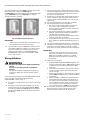
Fig. 6. EC/RM7830A and EC/RM7850A Relay Modules exploded view.
HONEYWELL
DUST
COVER
PURGE
TIMER
WIRING
SUBBASE
(Q7800A1005
plastic panel
mount version)
CAPTIVE
MOUNTING
SCREW
RUN/TEST
SWITCH
CONFIGURATION
JUMPERS
RELAY
MODULE
SEQUENCE
STATUS
LED PANEL
RESET
BUTTON
FLAME
AMPLIFIER
BURNER CONTROL
M15187B

EC7830A, RM7830A, EC7850A, RM7850A 7800 SERIES RELAY MODULES
32-00198—03 18
Fig. 7. Selectable site-configurable jumpers.
Table 7. Site-configurable jumper options.
IMPORTANT
Clipping site-configurable jumpers after 200
hours of operation results in a nonresettable Code
110, LOCKOUT. The relay module must be
replaced.
Flame Signal Measurement
Measure the flame signal at the appropriate times as
defined in the applicable flame amplifier specifications.
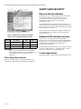
SAFETY AND SECURITY
Physical device protection
Device shall be accessible to authorized personnel only –
Installation on publicly accessible places is not
recommended as this could lead to unwanted and
potentially unsafe changes to device (wiring,
configuration, etc).
It is recommended to lock the device in an enclosed
cabinet with access allowed only to approved and trained
personnel. Also, it is strongly advised to keep all the wiring
of device physically secure.
Physical protection of the device is applied via Run/Test
switch label/seal. It is intended to prevent and detect
unauthorized access.
Modbus & DDL Interface security
Any conducts critical to device functionality (DDL,
Modbus lines etc.) shall be physically protected (installed
outside public access) since they could be damaged or
tampered-with by unauthorized people, either
accidentally or for purpose.
Modbus RS-485 & DDL protocols do not support security
features. For DDL interface - only DDL devices shall be
connected to the Burner Controller DDL line.
License agreement
Copying and reverse engineering is prohibited by the law.
Jumper
Number Description Intact Clipped
JR1 First Safety Time 5 seconds 3 seconds
JR2 Main Trial Time 5 seconds 3 seconds
JR3 Airflow Switch No Yes
RUN/TEST SWITCH SELECTABLE CONFIGURATION
JUMPERS
M7701B

EC7830A, RM7830A, EC7850A, RM7850A 7800 SERIES RELAY MODULES
19 32-00198—03

EC7830A, RM7830A, EC7850A, RM7850A 7800 SERIES RELAY MODULES
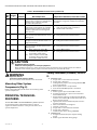
For More Information
The Honeywell Thermal Solutions family of products includes
Honeywell Combustion Safety, Eclipse, Exothermics, Hauck,
Kromschröder and Maxon. To learn more about our products,
visit ThermalSolutions.honeywell.com or contact your
Honeywell Sales Engineer.
Honeywell Process Solutions
Honeywell Thermal Solutions (HTS)
1250 West Sam Houston Parkway
South Houston, TX 77042
ThermalSolutions.honeywell
® U.S. Registered Trademark
© 2020 Honeywell International Inc.
32-00198—03 M.S. 03-20
Printed in United States
-
 1
1
-
 2
2
-
 3
3
-
 4
4
-
 5
5
-
 6
6
-
 7
7
-
 8
8
-
 9
9
-
 10
10
-
 11
11
-
 12
12
-
 13
13
-
 14
14
-
 15
15
-
 16
16
-
 17
17
-
 18
18
-
 19
19
-
 20
20


Honeywell EC7830A, RM7830A, EC7850A, RM7850A Operating instructions
- Type
- Operating instructions
Ask a question and I''ll find the answer in the document
Finding information in a document is now easier with AI
Related papers
-
Honeywell ST7800A,C Plug-In Purge Timer Operating instructions
-
-
-
-
-
-
-
-
-
Other documents
-
 Kromschroder Fulton 7800 SERIES System Annunciation Diagnostics and Troubleshooting Operating instructions
-
Greenheck 7800 series Installation guide
-
 2nd Ave. 7800 Series Relay Module User manual
-
Hauck Single Burner Control SBC 1.0AG Operating instructions
-
-
 Applied Air GAS-FIRED HEATERS Installation & Operation Instruction
-
-
Trane Horizon OAGD240A Installation, Operation and Maintenance Manual
-
-
Thomas & Betts LDAP 1200 User manual


