Page is loading ...

INSTALLATION INSTRUCTIONS
32-00208-01
SIL3
Capable
7800 SERIES
RM7896D Relay Module
APPLICATION
The Honeywell RM7896D1027 is a microprocessor based
integrated burner control for automatically fired gas, oil, or
combination fuel single burner applications. The
RM7896D1027 consists of the Relay Module. Subbase,
Amplifier and Purge Card are required to complete the
system. Options include Keyboard Display Module,
Personal Computer Interface, Data ControlBus™ Module,
Remote Display Module, First-Out Expanded Annunciator
and Combustion System Manager® Software.
NOTE: The RM7896D1027 differs from the standard
RM7896D as follows:
1. Ignition terminal no. 10 shuts off five seconds
into the Pilot flame Establishing Period.
2. Post Purge has 60 seconds duration.
3. PURGE STATUS LED replaces the FLAME LED.
4. POWER LED blinks a fault code when device/
system is in alarm.
This document covers the following models:
RM7896D1027
RM7896D2027
This document provides installation and static checkout
instructions. Other applicable publications are:
Table 1. Other applicable publications
SPECIFICATIONS
SIL 3 Capable:
SIL 3 Capable in a properly designed Safety Instrumented
System. See form 65-0312 for Certificate Agreement
APPROVALS:
Underwriters Laboratories Inc. Listed: File No. MP268.
UL 372 and 60730-2-5 / CSA C22.2 No. 60730-2-5.
Factory Mutual Approved: Report No. 1V9A0 AF.
Swiss Re (formerly Industrial Risk Insurers): Acceptable.
Federal Communications Commission: Part 15, Class B,
Emissions.
Exida: Certificate HCC 1702010 C001. IEC 61508:2010
Parts 1-7, SIL 3 capable.
EAC Russia
Form
Number Description
63-2278 Q7700A Network Interface Unit Product Data
65-0084 Q7800A,B 22-Terminal Wiring Subbase
Product Data
65-0090 S7800A 2-line VFD Keyboard Display Module
Product Data
32-00110 S7800A 4-Line LDC Keyboard display module
product data
65-0091 S7810A Data ControlBus Module™ Product
Data
65-0095 S7820 Remote Reset Module Product Data
65-0097 221729C Dust Cover Packing Sheet
65-0101 S7830 Expanded Annunciator Product Data
32-00235 R7824, R7847, R7848, R7849, R7851, R7861,
R7886 Flame Amplifiers for the 7800 SERIES
Product Data
65-0131 221818A Extension Cable Assembly Product
Data
65-0229 7800 SERIES RELAY MODULES Checkout
and Test
32-00156 RM7895A,B,C,D/EC7895A,C; RM7896A,C,D
7800 SERIES RELAY MODULES
Form
Number Description

7800 SERIES RM7896D RELAY MODULE
32-00208-01 2
INSTALLATION
WARNING
Fire or Explosion Hazard.
Can cause severe injury, death or property
damage.
Prevent possible hazardous burner operation.
Verify safety requirements each time a control is
installed on a burner.
When Installing this Product…
1. Read these instructions carefully. Failure to follow
them could damage the product or cause a
hazardous condition.
2. Check the ratings given in the instructions and
marked on the product to make sure the product is
suitable for your application.
3. Installer must be a trained, experienced, flame
safeguard service technician.
4. After installation is complete, check out the product
operation as provided in the instructions.
WARNING
Electrical Shock Hazard.
Can cause serious injury or death.
Disconnect the power supply before beginning
installation. More than one power supply
disconnection can be involved.
1. Wiring connections for the RM7896 are unique.
Refer to Fig. 3 for proper subbase wiring.
2. Wiring must comply with all applicable codes,
ordinances and regulations.
3. Wiring, where required, must comply with NEC Class
1 (Line Voltage) wiring.
4. Loads connected to the RM7896 must not exceed
those listed on the device label or in the specifica-
tions in form 32-00156.
5. Limits and interlocks must be rated to simultane-
ously carry and break current to the ignition trans-
former, pilot valve, and main fuel valve(s).
6. All external timers must be listed or component
recognized by authorities who have jurisdiction for
the specific purpose for which they are used.
IMPORTANT
1. For on-off gas-fired systems, some authorities
who have jurisdiction prohibit the wiring of any
limit or operating contacts in series between the
flame safeguard control and the main fuel valve(s).
2. Two flame detectors can be connected in parallel
with the exception of Infrared Flame Detectors
(C7015).
3. This equipment generates, uses, and can radiate
radio frequency energy, and if not installed and
used in accordance with the Instructions Manual,
can cause interference with radio communication.
It has been tested and found to comply with the
limits for a Class A computing device pursuant to
Subpart J of Part 15 of FCC Rules, which are
designed to provide reasonable protection against
such interference when operated in a commercial
environment. Operation of this equipment in a
residential area is likely to cause interference, in
which case, users at their own expense will be
required to take whatever measures may be
required to correct the interference. Any
unauthorized modification of this equipment can
result in the revocation of the owner’s authority to
continue its operation.
Canadian EMI:
This digital apparatus does not exceed the Class A limits
for radio noise emission from digital apparatus set out in
the Radio Interference Regulations of the Canadian
Department of Communications.
Le présent appareil numérique n’émet pas de bruits
radioélectriques dépassant les limites applicables aux
appareils numériques de la Classe A prescrites dans le
Règlement sur le brouillage radioeléctrique édicté par le
ministère des Communications du Canada.
Humidity
Install the RM7896D where the relative humidity never
reaches the saturation point. The RM7896D is designed to
operate in a maximum 85 percent relative humidity
continuous, noncondensing moisture environment.
Condensing moisture can cause a safety shutdown.
Vibration
Do not install the RM7896D where it can be subjected to
vibration in excess of 0.5G continuous maximum
vibration.
Weather
The RM7896D is not designed to be weather tight. If
installed outdoors, the RM7896D must be protected by an
approved weather-tight enclosure.

7800 SERIES RM7896D RELAY MODULE
3 32-00208-01
Relay Module and Subbase
Compatiblity
NOTE: There are several different subbase models that
can be purchased. It is important to note which
subbase is compatible with the relay module
when purchasing new, repair or replacement
parts.
Series 1000 Relay Modules
All relay product codes that start with a 1 (example:
RM7840G1014/U) can be used with existing subbase
Q7800A1003/U and Q7800A1005/U.
Series 2000 Relay Modules
All relay product codes that start with a 2 (example:
RM7840G2014/U) must be used with subbase
Q7800A2003/U and Q7800A2005/U.
Subbase Compatibility
Any Relay Module in the 1000 Series with a Software
Revision level number starting with a "5" or greater will be
compatible with all subbase models both installed and
newly purchased. This includes (Q7800A1005/U,
Q7800B1003/U), and the 2000 Series subbases
(Q7800A2005/U, Q7800B2003/U).
See Fig. 1 for Software Revision Level number location on
the label (located on the rear of the relay module).
Any relay module in the new 2000 series will only be able
to be installed on subbase Q7800A2005/U,
Q7800B2003/U and will not be backward compatible with
any Q7800A1003/U and Q7800A1005/U subbases
already installed in the field.
Fig. 1. Software Revision Location
IMPORTANT
Make sure to check the relay model number and
the software revision level on the relay.
• If you attempt to place a 2000 series relay on a
non-compatible 1000 series subbase, you will
receive an error code of 101. This indicates that
you must
a) change out the subbase to a Q7800A2003/U or
Q7800A2005/U
or
b) choose a compatible 1000 series relay module
Mounting Wiring Subbase
NOTE: For installation dimensions, see Fig. 2 or 3.
1. Mount the subbase in any position except
horizontally with the bifurcated contacts pointing
down. The standard vertical position is
recommended. Any other position decreases the
maximum ambient temperature rating.
2. Select a location on a wall, burner or electrical panel.
The Q7800 can be mounted directly in the control
cabinet. Be sure to allow adequate clearance for
servicing, installation, access and removal of the
RM7896D, dust cover, flame amplifier, flame
amplifier signal voltage probes, Run/Test Switch,
electrical signal voltage probes and electrical field
connections.
3. For surface mounting, use the back of the subbase
as a template to mark the four screw locations. Drill
the pilot holes.
4. Securely mount the subbase using four no. 6 screws.
Fig. 2. Mounting dimensions of RM7896D Relay Module
and Q7800A Subbase in in. (mm).
NOTES: You might receive and error code 101 (via KDM) if
one of the following conditions exist:
a. The screws securing the relay to the subbase
are not tight enough, re-tighten to insure there
is no gap between the relay and the subbase.
b. If you attempt to place a 2000 series relay on a
non-compatible 1000 series subbase, This
indicates that you must:
— Change out the subbase to a
Q7800A2003/U or Q7800A2005/U
— Choose a compatible 1000 series relay mod-
ule
POWER
PILOT
PURGE
MAIN
ALARM
RESET
5
(127)
5 (127)
M10448
(133)
BURNER CONTROL
REMOVE ONLY FOR TERMINAL TEST ACCESS.
1
1
5-1/4

7800 SERIES RM7896D RELAY MODULE
32-00208-01 4
WIRING
1. For proper wiring, refer to Fig. 3. For proper remote
wiring of the Keyboard Display Module, refer to the
Specifications for the Keyboard Display Module
4-line LCD KDM (32-00110), Network Interface Unit
(63-2278), Data ControlBus™ Module (65-0091) or
Extension Cable Assembly (65-0131).
Fig. 3. Mounting dimensions of RM7896D Relay
Module and Q7800B Subbase in in. (mm).
WARNING
Electrical Shock Hazard and Equipment
Damage Hazard.
Can cause serious injury, death,
or damage to equipment.
Disconnect power supply from main disconnect
before beginning installation. More than one
disconnection can be involved
2. To prevent electrical shock and equipment damage,
disconnect the power supply from the main
disconnect before beginning installation. More than
one disconnection can be involved.
3. All wiring must comply with all appropriate electrical
codes, ordinances and regulations. Wiring, where
required, must comply with NEC Class 1 (Line
Voltage) wiring. Recommended wire size and type:
use no. 14, 16 or 18 copper conductor ((TTW60C or
THW75C or THHN90C) 600 volt insulation wire for
all line voltage terminals. For high temperature
installations, use wire selected for a temperature
rating above the maximum operating temperature.
All leadwires must be moisture resistant.
4. Recommended grounding practices:
a. Use the earth ground to provide a connection
between the subbase and the control panel or
the equipment. The earth ground wire must be
capable of conducting the current to blow the
20A fuse
(or breaker) in event of an internal short circuit.
The RM7896D needs a low impedance ground
connection to the equipment frame which, in
turn, needs a low impedance connection to earth
ground. For a ground path to be low impedance
at RF frequencies, the connection must be made
with minimum length conductors that have a
maximum surface area. Wide straps or brackets
are preferred rather than leadwires. Be careful to
make sure that mechanically tightened joints
along the ground path, such as pipe or conduit
threads or surfaces held together with fasteners,
are free of nonconductive coatings and are
protected against mating surface corrosion.
b. RM7896D: Each relay module has an earth
ground terminal that must be grounded to the
metal control panel with wire as short as possi-
ble. Each ground wire must be capable of carry-
ing a fault current equal to the rating of the
protective fuse (20A). A number 14 copper con-
ductor is adequate, but wide straps or brackets
are preferred rather than leadwires.
5. Recommended wire routing for flame detector
leadwires:
a. Do not run high voltage ignition transformer
wires in the same conduit with the flame detec-
tion wiring.
b. Do not route scanner wires in a conduit with line
voltage circuits.
c. Enclose scanner wires without armor cable in
metal cable or conduit.
d. Follow directions in flame detector Instructions.
6. Maximum wire lengths:
a. For the RM7896D, the maximum length of
leadwire to the terminal inputs is 300 feet (91.4
meters) (Control and Airflow Interlock).
b. For the flame detector leadwires, the maximum
flame sensor leadwire length is limited by the
flame signal strength.
7. Make sure loads do not exceed the terminal ratings.
Refer to the label on the RM7896D or to the ratings
in the Specifications; see Table 1 in form 32-00156.
8. Check the power supply circuit. The voltage and
frequency tolerance must match those of the
RM7896D. A separate power supply circuit can be
required for the RM7896D with the required
disconnect means and overload protection added.
9. Check all wiring circuits and complete the Static
Checkout (see Table 4 in form 32-00156) before
installing the RM7896D on the subbase.
10. Install all electrical connectors.
11. Restore power to the panel.
POWER
PILOT
PURGE
MAIN
ALARM
RESET
5
(127)
5 (127)
M10449
BURNER CONTROL
REMOVE ONLY FOR TERMINAL TEST ACCESS.
1
1
6-3/32 (155)

7800 SERIES RM7896D RELAY MODULE
5 32-00208-01
ASSEMBLY
Assembly instructions for the RM7896D1027 are identical
to those in 32-00156.
OPERATION
The RM7896D1027 has the following status LEDs:
• POWER • PILOT • PURGE • MAIN • ALARM
POWER LED provides fault identification when the
RM7896D1027 locks out on an alarm. Fault identification
is a series of fast and slow blinking LED lights. The fast
blinks identify the tens portion of the fault code (three fast
blinks is 30) while the slow blinks identify the units portion
of the fault code (two slow blinks is 2). Three fast blinks
followed by two slow blinks would be fault code 32. This
identifies a running interlock on during STANDBY. (See
Table 3 for Blinking Fault Code list.)
The LED code repeats as long as the fault exists. To clear
the fault, press the RESET button.
See Fig. 5 for the RM7896D1027 operating sequence.
CHECKOUT
Static Checkout
WARNING
Electrical Shock Hazard and Equipment Damage
Hazard.
Can cause serious injury, death or equipment
damage.
Line voltage is present on most terminal
connections when power is on. Use extreme care
when testing the system. Close all manual fuel
shutoff valve(s) before starting these tests.
1. Open the master switch before installing or
removing a jumper on the subbase.
2. Before continuing to the next test, remove all
test jumpers used in the previous test(s).
3. Replace all limits and interlocks not operating
properly. Do not bypass limits and interlocks.
After checking all wiring, perform this checkout before
installing the RM7896D1027 on the subbase. These tests
verify that the Q7800 Wiring Subbase is wired correctly
and that all external controllers, limits, interlocks,
actuators, valves, transformers, motors and other devices
are operating properly.
CAUTION
Equipment Damage Hazard.
Dielectric test can seriously damage equipment.
Do not perform a dielectric test with the
RM7896D1027 installed. Internal surge protectors
will break down and conduct current. This can
cause the RM7896D1027 to fail the dielectric test
or destroy the internal lightning and high current
transient protection components.
Equipment Recommended
1. Voltmeter (1M ohm/volt minimum sensitivity) set
on the 0 to 300 Vac range.
2. Two jumper wires; no. 14 wire, insulated,
12 inches (305 mm) long, with insulated alligator
clips at both ends.
General Instructions
1. Perform all applicable tests in Table 2, Static Check-
out, in the order listed.
2. Make sure that all manual fuel shutoff valves are
closed.
3. Raise the setpoint of the operating controller to sim-
ulate a call for heat.
4. For each test, open the master switch and install the
jumper wire(s) between the subbase wiring termi-
nals listed in the Test Jumpers column of Table 2.
5. Close the master switch before observing operation.
6. Read the voltage between the subbase wiring termi-
nals listed in the Voltmeter column of Table 2.
7. If there is no voltage or the operation is abnormal,
check the circuits and external devices described in
the last column of Table 2.
8. Check all wiring for correct connections, tight termi-
nal screws, correct wire, and proper wiring tech-
niques. Replace all damaged or incorrectly sized
wires.
9. Replace faulty controllers, limits, interlocks, actua-
tors, valves, transformers, motors and other devices
as required.
10. Obtain normal operation for each required test
before continuing the checkout.
11. After completing each test, be sure to remove the
test jumper(s).
The remainder of the RM7896D1027 checkout is the
same as provided in form 32-00156.

7800 SERIES RM7896D RELAY MODULE
32-00208-01 6
TROUBLESHOOTING
Use Table 3 to identify fault code numbers, possible system failure and recommended troubleshooting procedures.
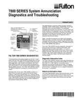
Fig. 4. Wiring the RM7896D.
Fig. 5. RM7896D operating sequence.
M10450
G
L2
3
5
6
7
8
9
10
F
(L1)
13
14
15
16
17
18
19
20
21
22
12
MASTER
SWITCH
MAIN FUEL
VALVE(S)
BURNER
CONTROLLER/LIMITS
BURNER MOTOR
(BLOWER)
5 SEC. INTERRUPTED
PILOT/IGNITION
RECTIFYING
FLAME ROD
120V, 50/60 Hz POWER SUPPLY. PROVIDE DISCONNECT
MEANS AND OVERLOAD PROTECTION AS REQUIRED.
DO NOT CONNECT ANY WIRES TO UNUSED TERMINALS.
FOR DIRECT SPARK IGNITION
(OIL OR GAS)
5 SECOND IGNITION
(EARLY SPARK TERMINATION)
DELAYED
MAIN VALVE
120V ALARM
L1
(HOT)
L2 1
8
9
10 IGNITION
TRANSFORMER
MAIN VALVE
1
Q7800
2
2
L2
4
AIRFLOW
INTERLOCK
INITIATE
PURGE PURGE
STANDBY
POWER POWER
PILOT
MAIN
ALARM
TIMED
PURGE
PURGE
POWER
PILOT
MAIN
ALARM
RUN
PURGE
POWER
PILOT
MAIN
ALARM
MFEP
POST PURGE
60 SEC
POWER
STANDBY
POWER
PILOT
MAIN
ALARM
PFEP
4 OR 10 SEC
POWER
START
POWERPOWER
M10451A
00 00 00 10 10
10
L1 6
9
21
8
4
76
5 SECONDS

7800 SERIES RM7896D RELAY MODULE
7 32-00208-01
Table 2. Static checkout.
Test
No.
Test
Jumpers Voltmeter
Normal Operation
If Operation is Abnormal,
Check the Items Listed Below
WARNING
Explosion Hazard and Electrical Shock Hazard.
Can cause serious injury, death or equipment damage.
Close all manual fuel shutoff valves before starting these tests.
IMPORTANT
Low fuel pressure limits, if used, could be open. Bypass them with jumpers for the remaining Static Test (if
required).
1 None 5-L2 Line voltage at terminal 5. 1. Master switch.
2. Power connected to the master switch.
3. Overload protection (fuse, circuit breaker) has not
opened the power line.
2 None 6-L2 Line voltage at terminal 6. 1. Limits.
2. Burner controller.
34-5 7-L2 1. Burner motor (fan or
blower) starts.
2. Line voltage at terminal 7
within 10 seconds.
1. Burner motor circuit.
a. Manual switch of burner motor.
b. Burner motor power supply, overload protection
and starter.
c. Burner motor.
4 5-10 — Ignition spark (if ignition
transformer is connected to
terminal 10).
1. Watch for spark or listen for buzz.
a. Ignition electrodes are clean.
b. Ignition transformer is okay.
55-8 — 1. Ignition spark (if ignition
transformer is connected to
terminal 8).
2. Automatic pilot valve opens
(if connected to terminal 8).
NOTE: Refer to wiring diagram
of system being tested.
1. Watch for spark or listen for buzz.
a. Ignition electrodes are clean.
b. Ignition transformer is okay.
2. Listen for click or feel head of valve for activation.
a. Actuator, if used.
b. Pilot valve.
6 5-9 — Automatic fuel valve9s) opens. If
using direct spark ignition, check
the first stage fuel valve(s)
instead of the pilot valve.
Same as test no. 5. If using direct spark ignition, check the
first stage fuel valve(s) instead of the pilot valve.
7 5-21 — Automatic delayed main fuel
valve(s) opens.
1. Listen for and observe operation of the delayed
main fuel valve(s) and actuator(s).
2. Valve(s) and actuator(s).
8 5-3 — Alarm (if used) turns on. 1. Alarm.
Final IMPORTANT
After completing these tests, open the master switch and remove all test jumpers from the subbase terminals.
Also, remove bypass jumpers from the low fuel pressure limits (if used).

7800 SERIES RM7896D RELAY MODULE
32-00208-01 8
Table 3. RM7896D1027 Blinking Fault Codes and Recommended Troubleshooting.
Fault Code System Failure Recommended Troubleshooting
Code 1-1
*Low AC Line
Voltage*
Low AC line detected. 1. Check the relay module and display module connections.
2. Reset and sequence the RM7896.
3. Check the 7800 power supply and make sure that frequency and voltage
meet specifications.
4. Check the backup power supply, as appropriate.
Code 1-2
*AC Quality
Problem*
Excessive noise or
device running on slow,
fast, or AC line dropout
detected.
Code 2-1
*Unexpected
Flame Signal*
Flame sensed when no
flame is expected
during STANDBY or
PURGE.
1. Check that flame is not present in the combustion chamber; correct any
errors.
2. Make sure that the flame amplifier and flame detector are compatible.
3. Check the wiring and correct any errors.
4. Remove the flame amplifier and inspect its connections. Reseat the ampli-
fier.
5. Reset and sequence the RM7896D.
6. If the code reappears, replace the flame amplifier and/or the flame detec-
tor.
7. If the fault persists, replace the relay module.
Code 2-2
*Flame Signal
Absent*
No-flame time present
at the end of the Pilot
Flame Establishing
Period; lost during the
Main Flame
Establishing Period or
during Run.
1. Measure the flame signal. If one exists, verify that it meets specifications.
2. Make sure that the flame amplifier and flame detector are compatible.
3. Inspect the main fuel valve(s) and valve connection(s).
4. Verify that the fuel pressure is sufficient to supply fuel to the combustion
chamber. Inspect the connections to the fuel pressure switches. make sure
they are functioning properly.
5. Inspect the Airflow Switch and make sure that it is functioning properly.
6. Check the flame detector sighting position; reset and recycle. Measure the
flame signal strength. Verify that it meets specifications. if not, refer to the
flame detector and/or flame amplifier checkout procedures in the
installation instructions.
7. Replace the flame amplifier and/or the flame detector, if necessary.
8. If the fault persists, replace the relay module.
Code 2-3
*Flame Signal
Overrange*
Flame signal value is
too high to be valid.
1. Make sure the flame detector and flame amplifier are compatible.
2. Remove the flame amplifier and inspect its connections. Reset the flame
amplifier.
3. Reset and sequence the RM7896D.
4. Check the flame detector sighting position; reset and recycle. Measure
flame strength. Verify that it meets specifications. If not, refer to the flame
detector and/or flame amplifier checkout procedures in the installation
instructions.
5. If the code reappears, replace the flame amplifier and/or the flame detec-
tor.
6. If the fault persists, replace the relay module.
Code 3-1
*Running/
Interlock
Switch
Problem*
Lockout interlock fault
during Prepurge.
1. Check wiring; correct any errors.
2. Inspect the fan; make sure there is no air intake blockage and that it is
supplying air.
3. Make sure the Lockout Interlock switches are functioning properly and the
contacts are free from contaminants.
4. Reset and sequence the RM7896D to Prepurge (place the TEST/RUN
switch in the TEST position, if available). Measure the voltage between ter-
minal 7 and G (ground); 120 Vac should be present.
5. If steps 1 through 4 are correct and the fault persists, replace the relay
module.

7800 SERIES RM7896D RELAY MODULE
9 32-00208-01
Code 3-2
*Running/
Interlock On
During
Standby*
Lockout interlock
powered at improper
point in sequence.
1. Check wiring to make sure that the Lockout Interlocks are connected
properly between terminals 6 and 7. Correct any errors.
2. Reset and sequence the RM7896D.
3. If the fault persists, measure the voltage between terminal 6 and G
(ground), then between terminal 7 and G. If there is 120 Vac at terminal 6
when the controller is off, the controller switch may be bad or is jumpered.
4. If steps 1 through 3 are correct and there is 120 Vac at terminal 7 while the
controller is closed and the fault persists, check for a welded or jumpered
Running Interlock or Airflow Switch. Correct any errors.
5. If steps 1 through 4 are correct and the fault persists, replace the relay
module.
Code 4-1
*Purge Card
Problem*
No purge card or the
purge card timing has
changed from the
original configuration.
1. Make sure the purge card is seated properly.
2. Inspect the purge card and the connector on the relay module for any
damage or contaminants.
3. Reset and sequence the RM7896D.
4. If the fault code reappears, replace the purge card.
5. Reset and sequence the RM7896D.
6. If the fault code persists, replace the relay module.
Code 4-2
*Wiring
Problem/
Internal Fault*
Pilot (ignition) valve
terminal, Main valve,
Ignition or Pilot Valve 2
was on when it should
be off.
WARNING
Electrical Shock Hazard, Fire or Explosion Hazard.
Can cause serious injury, death or equipment damage.
Remove system power and turn off power supply.
1. Remove system power and turn off fuel supply.
2. Check wiring, correct any errors.
3. Inspect Pilot Fuel Valve(s), both places, and connections.
4. Reset and sequence the RM7896D.
5. If the fault persists, replace the relay module.
Code 4-3
*Flame
Amplifier
Problem*
Flame not sensed, or
sensed when checked.
1. Check wiring; correct any errors.
2. Make sure the flame amplifier and flame detector are compatible.
3. Remove the flame amplifier and inspect the connections. Reseat the
amplifier.
4. Reset and sequence the RM7896D.
5. If the code reappears, replace the flame amplifier and/or the flame detec-
tor.
6. If the fault persists, replace the relay module.
Code 4-4
*Configuratio
n Jumper
Problem*
The configuration
jumpers differ from the
sample taken at
startup.
1. Inspect the jumper connections. Make sure the clipped jumpers were
completely removed.
2. Reset and sequence the RM7896D.
3. If the fault persists, replace the relay module.
Code 4-5
*Incompatible
Subbase*
Installed subbase is
incompatible with this
relay module.
1. Check that the subbase matches the installed Relay module series.
2. Replace the relay module with a compatible model.
Code 6-1
*Internal
Faults*
Relay Module self-test
failure.
1. Reset and sequence the RM7896D.
2. If fault reappears, remove power from the device, reapply power, then reset
and sequence the RM7896D.
3. If the fault persists, replace the relay module.
Table 3. RM7896D1027 Blinking Fault Codes and Recommended Troubleshooting. (Continued)
Fault Code System Failure Recommended Troubleshooting

7800 SERIES RM7896D RELAY MODULE
32-00208-01 10
Code 6-2
*Internal
Faults*
Relay Module Self-Test
failure.
1. Reset and sequence the Relay Module.
2. If fault reappears, remove power from the device, reapply power, then reset
and sequence the Relay Module.
3. If fault does not repeat on the next cycle, check for electrical noise being
copied into the Relay Module through the external loads or possibly an
electrical grounding issue.
4. If the fault persists, replace the Relay Module.
Code 6-3
*Device
Specific Fault*
Fault with special OEM
input circuits.
1. Check wiring and operation of special OEM inputs.
2. Reset and sequence the Relay Module.
3. If fault reappears, remove power from the device, reapply power, then reset
and sequence the Relay Module.
4. If the fault does not repeat on the next cycle, check for electrical noise
being copied into the Relay Module through the external loads or possibly
an electrical grounding issue.
5. If the fault persists, replace the Relay Module.
Code 6-4
*Accessory
Fault*
VPS setup 1. Make sure RM VP is programmed.
2. T6 and T17 powered at the same time—correct wiring.
3. Reset control if fault persists. Replace relay module.
Code 7-7
*Unrecognized
Fault*
Unrecognized at this
time.
—
Table 3. RM7896D1027 Blinking Fault Codes and Recommended Troubleshooting. (Continued)
Fault Code System Failure Recommended Troubleshooting

7800 SERIES RM7896D RELAY MODULE
11 32-00208-01
SAFETY AND SECURITY
Physical device protection
Device shall be accessible to authorized personnel only –
Installation on publicly accessible places is not
recommended as this could lead to unwanted and
potentially unsafe changes to device (wiring,
configuration, etc).
It is recommended to lock the device in an enclosed
cabinet with access allowed only to approved and trained
personnel. Also, it is strongly advised to keep all the wiring
of device physically secure.
Physical protection of the device is applied via Run/Test
switch label/seal. It is intended to prevent and detect
unauthorized access.
Modbus & DDL Interface security
Any conducts critical to device functionality (DDL,
Modbus lines etc.) shall be physically protected (installed
outside public access) since they could be damaged or
tampered-with by unauthorized people, either
accidentally or for purpose. Modbus RS-485 & DDL
protocols do not support security features. For DDL
interface - only DDL devices shall be connected to the
Burner Controller DDL line.
License agreement
Copying and reverse engineering is prohibited by the law.

7800 SERIES RM7896D RELAY MODULE
For More Information
The Honeywell Thermal Solutions family of products includes
Honeywell Combustion Safety, Eclipse, Exothermics, Hauck,
Kromschröder and Maxon. To learn more about our products,
visit ThermalSolutions.honeywell.com or contact your
Honeywell Sales Engineer.
Honeywell Process Solutions
Honeywell Thermal Solutions (HTS)
1250 West Sam Houston Parkway
South Houston, TX 77042
ThermalSolutions.honeywell
® U.S. Registered Trademark
© 2019 Honeywell International Inc.
32-00208—01 M.S. 07-19
Printed in United States
/