Page is loading ...

OPERATING INSTRUCTIONS
DM-2000/DM-2001
DIGITAL MULTIMETER
WITH AC/DC CLAMP SENSOR
PLEASE READ THESE OPERATING INSTRUCTIONS CAREFULLY
Misuse and or abuse of these instruments cannot be prevented by any printed
word and may cause injury and/or equipment damage. Please follow all these
instructions and measurement procedures faithfully and adhere to all standard
industry safety rules and practices.
1.SAFETY WARNINGS
This instrument has been designed and tested according to IEC Publication 61010: Safety
Requirements for Electronic Measuring Apparatus. This instruction manual contains warnings
and safety rules which must be observed by the user to ensure safe operation of the instrument
and to retain it in safe condition. Therefore, read through these operating instructions before
starting using the instrument.
WARNING
• Read through and understand instructions contained in this manual before starting to
use the instrument.
•Save and keep the manual handy to enable quick reference whenever necessary.
•Be sure to use the instrument only in its intended applications and to follow measurement
procedures described in the manual.
•Be sure to understand and follow all safety instructions contained in the manual.
Failure to follow the above instructions may cause injury, damage to the instrument and/or
damage to equipment under test.
The symbol indicated on the instrument means that the user must refer to related parts of
the manual for safe operation of the instrument. Be sure to carefully read the instructions
following each symbol in this manual.
DANGER is reserved for conditions and actions that are likely to cause serious or
fatal injury.
WARNING is reserved for conditions and actions that can cause serious or fatal injury.
CAUTION is reserved for conditions and actions that can cause minor injury or
instrument damage.
!
!
!
!
!
DANGER
•Never make measurement on circuits with a maximum voltage difference of 600VAC/DC
or greater between conductors (300VAC/DC or greater between a conductor and ground).
•Do not attempt to make measurement in the presence of flammable gasses. Otherwise,
the use of the instrument may cause sparking, which leads to an explosion.
•Never attempt to use the instrument if its surface or your hand is wet.
•Do not exceed the maximum allowable input of measuring ranges.
• Never open the battery compartment cover while making measurement.
A.W. SPERRY INSTRUMENTS, INC.
245 MARCUS BLVD., HAUPPAUGE, NEW YORK 11788
Phone: 800-645-5398 Toll Free (N.Y. and Alaska call collect 631-231-7050)
Fax: 631-434-3128
!
WARNING
•Never attempt to make any measurement, if any abnormal conditions are noted, such
as broken case, cracked test leads and exposed metal parts.
•Do not turn the Function Selector Switch while the test leads are connected to the circuit
under test.
•Do not install substitute parts or make any modification to the instrument. Return the
instrument to Sperry for repair or re-calibration.
• Do not try to replace the batteries if the surface of the instrument is wet.
•Always disconnect the clamp sensor and the test leads from the circuit under test and
switch off the instrument before opening the battery compartment cover for battery
replacement.
!
CAUTION
• Make sure that the Function Selector Switch is set to an appropriate position before
making measurement.
•Always make sureto place the test leads in the test lead holder before making current
measurement.
•Do not expose the instrument to the direct sun, extreme temperatures or dew fall.
•Besureto set the Function Selector Switch to the "OFF" position after use. When the
instrument will not be used for a long period of time, place it in storage after removing
the batteries.
•Use a damp cloth and detergent for cleaning the instrument. Do not use abrasives or
solvents.
!
2.FEATURES
•Permits AC/DC current measurement up to 60A using a clamp sensor that comes standard
with the instrument
•Open Jaw Current Clamp Sensor for ease of use in crowded cable areas and other tight places
•Auto-power-save function
•Continuity Buzzer
•Data hold function to freeze the readings
•LCD with a 3400 count full scale bar graph
•Shock absorbing holster allows easy lead storage
•Designed to international safety standard IEC61010-1: over-voltage category CAT.III, 300V
and pollution degree 2.
• UL listed to both US and Canadian Standards
• Limited One Year Warranty
3.SPECIFICATIONS
• Measuring Ranges and Accuracy (at 23ºC
±
5ºC, relative humidity 75% or less)
AC Current A
MODEL Range Measuring Range Accuracy
2000 60A 0-60.0A 2.0%rdg
±
5dgt(50/60Hz)
2001 100A 0-100.0A 2.0%rdg
±
5dgt(50/60Hz)
DC Current A
MODEL Range Measuring Range Accuracy
2000 60A 0-
±
60.0A 2.0%rdg
±
5dgt(50/60Hz)
2001 100A 0-
±
100.0A 2.0%rdg
±
5dgt(50/60Hz)
AC Voltage V Input impedance: 10M
Range Measuring Range Accuracy
3.4V
34V
±
1.5rdg
±
5dgt(50-400Hz)
340V
600V
DC Voltage V Input impedance: 10M Ω
Range Measuring Range Accuracy
340mV
3.4V
34V
±
1.5rdg
±
4dgt
340V
600V
Resistance Ω/
Range Measuring Range Accuracy
340 Ω
3.4k Ω
34k Ω
340k Ω
3.4M Ω
24M Ω
Frequency Hz
Range Measuring Range Accuracy
Current 0-3.399kHz / 3.4kHz-10kHz
±
0.1%rdg
±1
dgt
(Auto-ranging)
Voltage 0-3.399kHz / 3.4kHz-33.99kHz/34kHz-300kHz
±
0.1%rdg
±1
dgt
(Auto-ranging)
• Safety Standard IEC 61010-1
over-voltage category CAT.Ö°,300V, pollution degree 2
over-voltage category CAT.Ö†,600V, pollution degree 2
IEC 61010-2-031
IEC 61010-2-032
IEC 61326 (EMC)
• Operating System Dual integration
• Display Liquid crystal display with maximum reading of 3399
as well as units and annunciators
Bar graph with maximum points of 33
• Over Input Indication “OL” on the LCD ( Ωranges only)
• Auto-ranging Operation Shifts to the next higher range when bar graph
increases to 33 points
Shifts to the next lower range when bar graph
decreases to 3 points
•Sample Rate Numeric reading: about 400ms,
bar graph: about 20ms
• Accuracy-insured 23ºC
±
5ºCrelative humidity 75% or less
Temperature and (without condensation)
Humidity Ranges
•Operating Temperature 0-40ºC,relative humidity 85% or less
and Humidity Range (without condensation)
• Storage Temperature -20-60ºC, relative humidity 85% or less
and Humidity Range (without condensation)
• Source Two 1.5VDC R03 (UM-4) “AAA” batteries
• Current Consumption Approx. 10mA
• Power-save Function Shifts to the power-save state about 10 minutes after
the last switch operation
(current consumption: approx. 10 µ A)
• Overload Protection AC/DC current ranges: MODEL2000 AC/DC 72A for
10 seconds
AC/DC current ranges: MODEL2001 AC/DC 120A for
10 seconds
AC/DC voltage ranges: AC/DC 720V for 10 seconds
Resistance ranges: AC/DC 720V for 10 seconds
Frequency ranges: AC/DC 720V for 10 seconds
• Withstand Voltage AC3700V for 1 minute between electrical circuit and
housing case
• Insulation Resistance 10MÉ∂or greater at 1000V between electrical circuit
and housing case
• Conductor Size MODEL2000 Approx. 6mm diameter max.
MODEL2001 Approx. 10mm diameter max.
• Dimensions MODEL2000 128(L) x 87(W) x 24(D)mm
MODEL2001 128(L) x 92(W) x 27(D)mm
• Weight MODEL2000 Approx. 210g
MODEL2001 Approx. 220g
•Accessories Two R03 (UM-4) “AAA” batteries
Instruction Manual
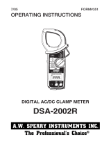
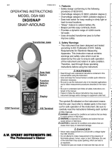
4. INSTRUMENT LAYOUT
5.PREPARATIONS FOR MEASUREMENT
(1) Checking battery voltage
Set the Function Selector Switch to any position other than the OFF position. If the
marks on the display are clearly legible without symbol "BATT" showing, battery voltage
is OK. If the display blanks or "BATT" is indicated, replace the batteries according to
section 8: Battery Replacement.
AC/DC Clamp Sensor
NOTE
When the instrument is left powered on, the auto-power-save function automatically
shuts the power off; The display blanks even if the Function Selector Switch is set to
aposition other than the OFF position in this state. Topower on the instrument, turn
the Function Selector Switch or press the Data Hold Button. If the display is still
blank, the batteries are exhausted. Replace the batteries.
(2) Make sure that the Function Selector Switch is set to
the appropriate range.
Also make sure that data hold function is
not enabled. If inappropriate range is
selected, desired measurement cannot
be made.
(3) Install Test Lead to the Holster on the side of body
It is now possible to measure with seeing
the LCD Display. Keep Test Lead installed
in the Holster.
6. HOW TO MAKE MEASUREMENT
6-1 Current Measurement
DANGER
•In order to avoid possible shock hazard, never make measurement on circuits with
amaximum voltage difference of 600VAC/DC or greater between conductors
(300VAC/DC or greater between a conductor and ground).
• Do not make measurement with the test leads connected to the circuit under test.
Never make measurement with the batterycompartment cover removed.
CAUTION
• When handling the clamp sensor, exercise caution not to apply excessive shocks or
vibration to the sensor.
• Maximum measurable conductor size is MODEL2000 6mm / MODEL2001 10mm in
diameter.
!
!
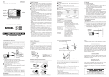
Correct Wrong
Conductor
Adjust a
conductor to
the center of
the arrow
MODEL 2000 MODEL2001
6-1-1 DC Current Measurement
(1) Set The Function Selector Switch to the “– A” position.
("DC" and "AUTO" marks areshown on the top of the display.)
(2) Turnthe 0 (Zero) ADJ knob to set the reading of the multimeter to zero. (If this
zeroadjustment is made incorrectly,measurement errors will result.)
(3) Adjust one of the conductors to the center of the clamp sensor's arrow.
(When the position of the conductor is not at the center of the arrow, an error
may occur)
Measured value is shown on the display.
Note: When current flows from the upside to the underside of the instrument, the
polarity of the reading is positive (+). Otherwise, the polarity of the reading is
negative (-).
6-1-2 AC Current Measurement
(1) Set the Function Selector Switch to “ A."
(“AC” and “AUTO” marks are shown on the top of the LCD.)
(2) Adjust one of the conductors to the center of the clamp sensor's arrow.
(When the position of the conductor is not at the center of the arrow, an error may
occur.)
Measured value is shown on the display.
Note: Unlike DC current measurement, zeroadjustment is not necessary. There is
not polarity indication either.
6-2 Voltage Measurement
DANGER
•In order to avoid possible shock hazard, never make measurement on circuits
with a maximum voltage difference of 600VAC/DC or greater between
conductors (300VAC/DC or greater between a conductor and ground).
• Do not make measurement with the battery compartment cover removed.
6-2-1 DC Voltage Measurement
(1) Set the Function Selector Switch to “ V.”
("DC" and "AUTO" marks areshown on the top of the LCD.)
(2) Connect the red test lead to the positive (+) side of the circuit under test and
the black test lead to the negative (-) side. Measured voltage value is shown
on the display.
When the connection is reversed, “-” is shown on the display.
6-2-2 AC Voltage Measurement
(1) Set the Function Selector Switch to “ V.”
(“AC” and “AUTO” marks are shown on the LCD.)
(2) Connect the test leads to the circuit under test.
Measured voltage value is shown on the display.
6-3 Resistance Measurement
DANGER
• Never make measurement on circuits that are live.
• Never make measurement with the battery compartment cover removed.
(1) Set the Function Selector Switch to “Ω/.”
(2) Check that the display shows over-range. Short the test leads and check that
the buzzer beeps and the display reads zero.
(3) Connect the test leads to the circuit under test. Measured resistance value is
shown on the display. When the measured value is below about 30 Ω,the
buzzer beeps.
Note: When the test leads are shorted, the display may read a small resistance value.
This is the resistance of the test leads.
If thereis an open in either of the test leads, "OL" is shown on the display.On the
340 Ωrange, “ ” is shown on the left side of the LCD.
•
•
!
!
6-4 Frequency Measurement
DANGER
• In order to avoid possible shock hazard, never make measurement on circuits with a maxi
mum voltage difference of 600VAC/DC or greater between conductors (300VAC/DC or
greater between a conductor and ground).
• Do not make measurement with the test leads connected to the circuit under test.
Never make measurement with the battery compartment cover removed.
•Do not make current measurement with the test leads connected to the circuit under test.
(1) Set the Function Selector Switch to “Hz.”
(2) Measuring frequency of current:
Adjust one of the conductors to the center of the clamp sensor's arrow.
Measured value is shown on the display.
Measuring frequency of voltage:
Connect the test leads to the circuit under test. Measured frequency is
shown on the display.
Note: Measuring range of current frequency is 0-10kHz with minimum measurable
input of MODEL2000 16A(Typ)/MODEL2001 10A(Typ).
Measuring range of voltage frequency is 0-300kHz with minimum measurable input of
10V(Typ).
When measuring frequency, do not attach the clamp sensor and the test leads to the
circuit under test simultaneously.
7
7. OTHER FUNCTIONS
7-1 Auto-Power-Save Function
NOTE
A small amount of current is consumed even in the power-save state. Make sure to set the
Function Selector Switch to the OFF position when the instrument is not used.
This function helps to avoid unwanted exhaustion of the batteries and helps extend battery
life. The instrument automatically shifts to the power-save state about 10 minutes after the
last Function Selector Switch or other switch operation.
To return to the normal state: Turn the Function Selector Switch or press the Data Hold
Button twice to exit the power-save state and enable measurement functions.
!
Prohibition
7-2 Data Hold Function
This is a function to freeze a measured value on the display. Press the Data Hold
Button once to hold the current reading. In this data hold state, the reading is held
even if input varies. “H” and “ ” marks are shown on the LCD instead of “AUTO”
mark.
To exit the data hold state, press the Data Hold Button again.
7-3 Range Hold Function
The instrument defaults to auto-ranging (“AUTO” is shown on the LCD).
Pressing the Range Hold Button enables manual selection among measurement
ranges ( mark is shown on the LCD instead of “AUTO” mark)
Press the Range Hold Button to select a higher range.
To switch from manual range selection to auto-ranging, press down the Range
Hold Button for about one seconds, or turn the Function Selector Switch to
another position before setting it back to the current range.
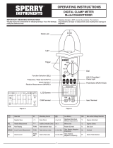
8. BATTERY REPLACEMENT
WARNING
• In order to avoid possible shock hazard, always disconnect the test leads from the
circuit under test and set the Function Selector Switch to the OFF position before
trying to replace the batteries.
CAUTION
• Do not mix new and old batteries.
• Install batteries in the orientation as shown inside the battery compartment,
observing correct polarity.
When the battery voltage warning mark "BATT" is shown on the top left corner of the
LCD, replace the batteries. Note that the display blanks and “BATT” mark is not
shown if the batteries are completely exhausted.
(1) Set the Function Selector Switch to “OFF.”
(2) Remove the instrument from the holster.
(3) Loosen the battery-compartment-cover-fixing screw on the lower back of
the instrument.
(4) Replace the batteries with two new R03 (UM-4) “AAA” 1.5V batteries.
(5) Put the battery compartment cover back in place and tighten the screw.
Battery
Compartment
Cover
!
!
Screw
Batteries
LIMITED WARRANTY
A.W. Sperry Instruments warrants that this A.W. Sperry
Instrument has been carefully tested, inspected, and
warranted for one year from the date of purchase by the
original end user, provided the instrument has not been
misused, damaged due to negligence, neglect or
unauthorized repair, abused or used contrary to the
operating instructions. Instruments and proof of
purchase in the form of a legible copy or original of the
sales receipt clearly identifying the distributor, model
number and date of purchase must be returned to A.W.
Sperry Instruments Inc., Attention: Customer Service
Center, 245 Marcus Blvd., Hauppauge, NY 11788,
postage prepaid for examination and verification of
manufacturing defect under warranty. A.W. Sperry shall
be the sole judge of such defect. The liability of A.W.
Sperry Instruments, Inc. shall be limited to the repair or
replacement at its sole option of any defective product.
A.W. SPERRY INSTRUMENTS, INC.
245 MARCUS BLVD., HAUPPAUGE, NEW YORK 11788
Phone: 800-645-5398 Toll Free (N.Y. and Alaska call collect 631-231-7050)
Fax: 631-434-3128
Battery Voltage Warning Data Hold
Auto Range Unit
Bar Graph
Buzzer
Manual
Range
AC/DC
DCA
Zero Adjust
Knob
LCD Display Test Lead
Range Hold Button
Data Hold Button
Function Selector Switch
Digital Multimeter
Holster
How to put test lead in.
Wind the lead around the folder
Test Leads
AC/DC Clamp Sensor
MODEL2001 MODEL2000
0-600V
(Auto ranging)
0-600V
(Auto ranging)
•
•
Measuring Range
0-33.99M Ω
(Auto-ranging)
±
1.0%rdg
±
3dgt
Buzzer beeps below 30
±
10 ΩTT
(Continuity buzzer works on
340 Ωrange only)
±
5%rdg
±
5dgt
±
15%rdg
±
5dgt
Electromagnetic RF field ≤1 V/m Altitude 2000M
compatibility ACV/DCV/OHMS/FREQUENCY total accuracy = specified accuracy
(IEC 61000-4-3) ACA/DCA total accuracy = specified accuracy+5dgt RF transmitters such as mobile
telephones may not be used in close proximity.
•
•
SPERRY
10/04 Form #325
SPERRY
SPERRY
SPERRY
•

OPERATING INSTRUCTIONS
DM-2000/DM-2001
DIGITAL MULTIMETER
WITH AC/DC CLAMP SENSOR
PLEASE READ THESE OPERATING INSTRUCTIONS CAREFULLY
Misuse and or abuse of these instruments cannot be prevented by any printed
word and may cause injury and/or equipment damage. Please follow all these
instructions and measurement procedures faithfully and adhere to all standard
industry safety rules and practices.
1.SAFETY WARNINGS
This instrument has been designed and tested according to IEC Publication 61010: Safety
Requirements for Electronic Measuring Apparatus. This instruction manual contains warnings
and safety rules which must be observed by the user to ensure safe operation of the instrument
and to retain it in safe condition. Therefore, read through these operating instructions before
starting using the instrument.
WARNING
• Read through and understand instructions contained in this manual before starting to
use the instrument.
•Save and keep the manual handy to enable quick reference whenever necessary.
•Be sure to use the instrument only in its intended applications and to follow measurement
procedures described in the manual.
•Be sure to understand and follow all safety instructions contained in the manual.
Failure to follow the above instructions may cause injury, damage to the instrument and/or
damage to equipment under test.
The symbol indicated on the instrument means that the user must refer to related parts of
the manual for safe operation of the instrument. Be sure to carefully read the instructions
following each symbol in this manual.
DANGER is reserved for conditions and actions that are likely to cause serious or
fatal injury.
WARNING is reserved for conditions and actions that can cause serious or fatal injury.
CAUTION is reserved for conditions and actions that can cause minor injury or
instrument damage.
!
!
!
!
!
DANGER
•Never make measurement on circuits with a maximum voltage difference of 600VAC/DC
or greater between conductors (300VAC/DC or greater between a conductor and ground).
•Do not attempt to make measurement in the presence of flammable gasses. Otherwise,
the use of the instrument may cause sparking, which leads to an explosion.
•Never attempt to use the instrument if its surface or your hand is wet.
•Do not exceed the maximum allowable input of measuring ranges.
• Never open the battery compartment cover while making measurement.
A.W. SPERRY INSTRUMENTS, INC.
245 MARCUS BLVD., HAUPPAUGE, NEW YORK 11788
Phone: 800-645-5398 Toll Free (N.Y. and Alaska call collect 631-231-7050)
Fax: 631-434-3128
!
WARNING
•Never attempt to make any measurement, if any abnormal conditions are noted, such
as broken case, cracked test leads and exposed metal parts.
•Do not turn the Function Selector Switch while the test leads are connected to the circuit
under test.
•Do not install substitute parts or make any modification to the instrument. Return the
instrument to Sperry for repair or re-calibration.
• Do not try to replace the batteries if the surface of the instrument is wet.
•Always disconnect the clamp sensor and the test leads from the circuit under test and
switch off the instrument before opening the battery compartment cover for battery
replacement.
!
CAUTION
• Make sure that the Function Selector Switch is set to an appropriate position before
making measurement.
•Always make sureto place the test leads in the test lead holder before making current
measurement.
•Do not expose the instrument to the direct sun, extreme temperatures or dew fall.
•Besureto set the Function Selector Switch to the "OFF" position after use. When the
instrument will not be used for a long period of time, place it in storage after removing
the batteries.
•Use a damp cloth and detergent for cleaning the instrument. Do not use abrasives or
solvents.
!
2.FEATURES
•Permits AC/DC current measurement up to 60A using a clamp sensor that comes standard
with the instrument
•Open Jaw Current Clamp Sensor for ease of use in crowded cable areas and other tight places
•Auto-power-save function
•Continuity Buzzer
•Data hold function to freeze the readings
•LCD with a 3400 count full scale bar graph
•Shock absorbing holster allows easy lead storage
•Designed to international safety standard IEC61010-1: over-voltage category CAT.III, 300V
and pollution degree 2.
• UL listed to both US and Canadian Standards
• Limited One Year Warranty
3.SPECIFICATIONS
• Measuring Ranges and Accuracy (at 23ºC
±
5ºC, relative humidity 75% or less)
AC Current A
MODEL Range Measuring Range Accuracy
2000 60A 0-60.0A 2.0%rdg
±
5dgt(50/60Hz)
2001 100A 0-100.0A 2.0%rdg
±
5dgt(50/60Hz)
DC Current A
MODEL Range Measuring Range Accuracy
2000 60A 0-
±
60.0A 2.0%rdg
±
5dgt(50/60Hz)
2001 100A 0-
±
100.0A 2.0%rdg
±
5dgt(50/60Hz)
AC Voltage V Input impedance: 10M
Range Measuring Range Accuracy
3.4V
34V
±
1.5rdg
±
5dgt(50-400Hz)
340V
600V
DC Voltage V Input impedance: 10M Ω
Range Measuring Range Accuracy
340mV
3.4V
34V
±
1.5rdg
±
4dgt
340V
600V
Resistance Ω/
Range Measuring Range Accuracy
340 Ω
3.4k Ω
34k Ω
340k Ω
3.4M Ω
24M Ω
Frequency Hz
Range Measuring Range Accuracy
Current 0-3.399kHz / 3.4kHz-10kHz
±
0.1%rdg
±1
dgt
(Auto-ranging)
Voltage 0-3.399kHz / 3.4kHz-33.99kHz/34kHz-300kHz
±
0.1%rdg
±1
dgt
(Auto-ranging)
• Safety Standard IEC 61010-1
over-voltage category CAT.Ö°,300V, pollution degree 2
over-voltage category CAT.Ö†,600V, pollution degree 2
IEC 61010-2-031
IEC 61010-2-032
IEC 61326 (EMC)
• Operating System Dual integration
• Display Liquid crystal display with maximum reading of 3399
as well as units and annunciators
Bar graph with maximum points of 33
• Over Input Indication “OL” on the LCD ( Ωranges only)
• Auto-ranging Operation Shifts to the next higher range when bar graph
increases to 33 points
Shifts to the next lower range when bar graph
decreases to 3 points
•Sample Rate Numeric reading: about 400ms,
bar graph: about 20ms
• Accuracy-insured 23ºC
±
5ºCrelative humidity 75% or less
Temperature and (without condensation)
Humidity Ranges
•Operating Temperature 0-40ºC,relative humidity 85% or less
and Humidity Range (without condensation)
• Storage Temperature -20-60ºC, relative humidity 85% or less
and Humidity Range (without condensation)
• Source Two 1.5VDC R03 (UM-4) “AAA” batteries
• Current Consumption Approx. 10mA
• Power-save Function Shifts to the power-save state about 10 minutes after
the last switch operation
(current consumption: approx. 10 µ A)
• Overload Protection AC/DC current ranges: MODEL2000 AC/DC 72A for
10 seconds
AC/DC current ranges: MODEL2001 AC/DC 120A for
10 seconds
AC/DC voltage ranges: AC/DC 720V for 10 seconds
Resistance ranges: AC/DC 720V for 10 seconds
Frequency ranges: AC/DC 720V for 10 seconds
• Withstand Voltage AC3700V for 1 minute between electrical circuit and
housing case
• Insulation Resistance 10MÉ∂or greater at 1000V between electrical circuit
and housing case
• Conductor Size MODEL2000 Approx. 6mm diameter max.
MODEL2001 Approx. 10mm diameter max.
• Dimensions MODEL2000 128(L) x 87(W) x 24(D)mm
MODEL2001 128(L) x 92(W) x 27(D)mm
• Weight MODEL2000 Approx. 210g
MODEL2001 Approx. 220g
•Accessories Two R03 (UM-4) “AAA” batteries
Instruction Manual
4. INSTRUMENT LAYOUT
5.PREPARATIONS FOR MEASUREMENT
(1) Checking battery voltage
Set the Function Selector Switch to any position other than the OFF position. If the
marks on the display are clearly legible without symbol "BATT" showing, battery voltage
is OK. If the display blanks or "BATT" is indicated, replace the batteries according to
section 8: Battery Replacement.
AC/DC Clamp Sensor
NOTE
When the instrument is left powered on, the auto-power-save function automatically
shuts the power off; The display blanks even if the Function Selector Switch is set to
aposition other than the OFF position in this state. Topower on the instrument, turn
the Function Selector Switch or press the Data Hold Button. If the display is still
blank, the batteries are exhausted. Replace the batteries.
(2) Make sure that the Function Selector Switch is set to
the appropriate range.
Also make sure that data hold function is
not enabled. If inappropriate range is
selected, desired measurement cannot
be made.
(3) Install Test Lead to the Holster on the side of body
It is now possible to measure with seeing
the LCD Display. Keep Test Lead installed
in the Holster.
6. HOW TO MAKE MEASUREMENT
6-1 Current Measurement
DANGER
•In order to avoid possible shock hazard, never make measurement on circuits with
amaximum voltage difference of 600VAC/DC or greater between conductors
(300VAC/DC or greater between a conductor and ground).
• Do not make measurement with the test leads connected to the circuit under test.
Never make measurement with the batterycompartment cover removed.
CAUTION
• When handling the clamp sensor, exercise caution not to apply excessive shocks or
vibration to the sensor.
• Maximum measurable conductor size is MODEL2000 6mm / MODEL2001 10mm in
diameter.
!
!
Correct Wrong
Conductor
Adjust a
conductor to
the center of
the arrow
MODEL 2000 MODEL2001
6-1-1 DC Current Measurement
(1) Set The Function Selector Switch to the “– A” position.
("DC" and "AUTO" marks areshown on the top of the display.)
(2) Turnthe 0 (Zero) ADJ knob to set the reading of the multimeter to zero. (If this
zeroadjustment is made incorrectly,measurement errors will result.)
(3) Adjust one of the conductors to the center of the clamp sensor's arrow.
(When the position of the conductor is not at the center of the arrow, an error
may occur)
Measured value is shown on the display.
Note: When current flows from the upside to the underside of the instrument, the
polarity of the reading is positive (+). Otherwise, the polarity of the reading is
negative (-).
6-1-2 AC Current Measurement
(1) Set the Function Selector Switch to “ A."
(“AC” and “AUTO” marks are shown on the top of the LCD.)
(2) Adjust one of the conductors to the center of the clamp sensor's arrow.
(When the position of the conductor is not at the center of the arrow, an error may
occur.)
Measured value is shown on the display.
Note: Unlike DC current measurement, zeroadjustment is not necessary. There is
not polarity indication either.
6-2 Voltage Measurement
DANGER
•In order to avoid possible shock hazard, never make measurement on circuits
with a maximum voltage difference of 600VAC/DC or greater between
conductors (300VAC/DC or greater between a conductor and ground).
• Do not make measurement with the battery compartment cover removed.
6-2-1 DC Voltage Measurement
(1) Set the Function Selector Switch to “ V.”
("DC" and "AUTO" marks areshown on the top of the LCD.)
(2) Connect the red test lead to the positive (+) side of the circuit under test and
the black test lead to the negative (-) side. Measured voltage value is shown
on the display.
When the connection is reversed, “-” is shown on the display.
6-2-2 AC Voltage Measurement
(1) Set the Function Selector Switch to “ V.”
(“AC” and “AUTO” marks are shown on the LCD.)
(2) Connect the test leads to the circuit under test.
Measured voltage value is shown on the display.
6-3 Resistance Measurement
DANGER
• Never make measurement on circuits that are live.
• Never make measurement with the battery compartment cover removed.
(1) Set the Function Selector Switch to “Ω/.”
(2) Check that the display shows over-range. Short the test leads and check that
the buzzer beeps and the display reads zero.
(3) Connect the test leads to the circuit under test. Measured resistance value is
shown on the display. When the measured value is below about 30 Ω,the
buzzer beeps.
Note: When the test leads are shorted, the display may read a small resistance value.
This is the resistance of the test leads.
If thereis an open in either of the test leads, "OL" is shown on the display.On the
340 Ωrange, “ ” is shown on the left side of the LCD.
•
•
!
!
6-4 Frequency Measurement
DANGER
• In order to avoid possible shock hazard, never make measurement on circuits with a maxi
mum voltage difference of 600VAC/DC or greater between conductors (300VAC/DC or
greater between a conductor and ground).
• Do not make measurement with the test leads connected to the circuit under test.
Never make measurement with the battery compartment cover removed.
•Do not make current measurement with the test leads connected to the circuit under test.
(1) Set the Function Selector Switch to “Hz.”
(2) Measuring frequency of current:
Adjust one of the conductors to the center of the clamp sensor's arrow.
Measured value is shown on the display.
Measuring frequency of voltage:
Connect the test leads to the circuit under test. Measured frequency is
shown on the display.
Note: Measuring range of current frequency is 0-10kHz with minimum measurable
input of MODEL2000 16A(Typ)/MODEL2001 10A(Typ).
Measuring range of voltage frequency is 0-300kHz with minimum measurable input of
10V(Typ).
When measuring frequency, do not attach the clamp sensor and the test leads to the
circuit under test simultaneously.
7
7. OTHER FUNCTIONS
7-1 Auto-Power-Save Function
NOTE
A small amount of current is consumed even in the power-save state. Make sure to set the
Function Selector Switch to the OFF position when the instrument is not used.
This function helps to avoid unwanted exhaustion of the batteries and helps extend battery
life. The instrument automatically shifts to the power-save state about 10 minutes after the
last Function Selector Switch or other switch operation.
To return to the normal state: Turn the Function Selector Switch or press the Data Hold
Button twice to exit the power-save state and enable measurement functions.
!
Prohibition
7-2 Data Hold Function
This is a function to freeze a measured value on the display. Press the Data Hold
Button once to hold the current reading. In this data hold state, the reading is held
even if input varies. “H” and “ ” marks are shown on the LCD instead of “AUTO”
mark.
To exit the data hold state, press the Data Hold Button again.
7-3 Range Hold Function
The instrument defaults to auto-ranging (“AUTO” is shown on the LCD).
Pressing the Range Hold Button enables manual selection among measurement
ranges ( mark is shown on the LCD instead of “AUTO” mark)
Press the Range Hold Button to select a higher range.
To switch from manual range selection to auto-ranging, press down the Range
Hold Button for about one seconds, or turn the Function Selector Switch to
another position before setting it back to the current range.
8. BATTERY REPLACEMENT
WARNING
• In order to avoid possible shock hazard, always disconnect the test leads from the
circuit under test and set the Function Selector Switch to the OFF position before
trying to replace the batteries.
CAUTION
• Do not mix new and old batteries.
• Install batteries in the orientation as shown inside the battery compartment,
observing correct polarity.
When the battery voltage warning mark "BATT" is shown on the top left corner of the
LCD, replace the batteries. Note that the display blanks and “BATT” mark is not
shown if the batteries are completely exhausted.
(1) Set the Function Selector Switch to “OFF.”
(2) Remove the instrument from the holster.
(3) Loosen the battery-compartment-cover-fixing screw on the lower back of
the instrument.
(4) Replace the batteries with two new R03 (UM-4) “AAA” 1.5V batteries.
(5) Put the battery compartment cover back in place and tighten the screw.
Battery
Compartment
Cover
!
!
Screw
Batteries
LIMITED WARRANTY
A.W. Sperry Instruments warrants that this A.W. Sperry
Instrument has been carefully tested, inspected, and
warranted for one year from the date of purchase by the
original end user, provided the instrument has not been
misused, damaged due to negligence, neglect or
unauthorized repair, abused or used contrary to the
operating instructions. Instruments and proof of
purchase in the form of a legible copy or original of the
sales receipt clearly identifying the distributor, model
number and date of purchase must be returned to A.W.
Sperry Instruments Inc., Attention: Customer Service
Center, 245 Marcus Blvd., Hauppauge, NY 11788,
postage prepaid for examination and verification of
manufacturing defect under warranty. A.W. Sperry shall
be the sole judge of such defect. The liability of A.W.
Sperry Instruments, Inc. shall be limited to the repair or
replacement at its sole option of any defective product.
A.W. SPERRY INSTRUMENTS, INC.
245 MARCUS BLVD., HAUPPAUGE, NEW YORK 11788
Phone: 800-645-5398 Toll Free (N.Y. and Alaska call collect 631-231-7050)
Fax: 631-434-3128
Battery Voltage Warning Data Hold
Auto Range Unit
Bar Graph
Buzzer
Manual
Range
AC/DC
DCA
Zero Adjust
Knob
LCD Display Test Lead
Range Hold Button
Data Hold Button
Function Selector Switch
Digital Multimeter
Holster
How to put test lead in.
Wind the lead around the folder
Test Leads
AC/DC Clamp Sensor
MODEL2001 MODEL2000
0-600V
(Auto ranging)
0-600V
(Auto ranging)
•
•
Measuring Range
0-33.99M Ω
(Auto-ranging)
±
1.0%rdg
±
3dgt
Buzzer beeps below 30
±
10 ΩTT
(Continuity buzzer works on
340 Ωrange only)
±
5%rdg
±
5dgt
±
15%rdg
±
5dgt
Electromagnetic RF field ≤1 V/m Altitude 2000M
compatibility ACV/DCV/OHMS/FREQUENCY total accuracy = specified accuracy
(IEC 61000-4-3) ACA/DCA total accuracy = specified accuracy+5dgt RF transmitters such as mobile
telephones may not be used in close proximity.
•
•
SPERRY
10/04 Form #325
SPERRY
SPERRY
SPERRY
•
/