INSTRUCTION MANUAL
KEW SNAP 2432/2433
KEW SNAP Series
LEAKAGE CURRENT TESTER
KEW SNAP 2432
KEW SNAP 2433
KYORITSU ELECTRICAL INSTRUMENTS WORKS, LTD.,
TOKYO, JAPAN
1. SAFETY WARNINGS
This instrument has been designed and tested according to IEC
Publication 61010: Safety Requirements for Electronic Measuring
Apparatus. This instruction manual contains warnings and safety
rules which must be observed by the user to ensure safe operation
of the instrument and to retain it in safe condition. Therefore, read
through these operating instructions before starting using the
instrument.
WARNING
●Read through and understand instructions contained in this
manual before starting using the instrument.
●Save and keep the manual handy to enable quick reference
whenever necessary.
●Be sure to use the instrument only in its intended applications
and to follow measurement procedures described in the
manual.
●Be sure to understand and follow all safety instructions
contained in the manual.
Not following the above instructions may cause injury, instrument
damage and/or damage to equipment under test.
The symbol indicated on the instrument means that the user
must refer to related parts of the manual for safe operation of the
instrument. Be sure to carefully read the instructions following
each symbol in this manual.
DANGER is reserved for conditions and actions that are likely
to cause serious or fatal injury.
WARNING is reserved for conditions and actions that can
cause serious or fatal Injury.
CAUTION is reserved for conditions and actions that can
cause minor injury or Instrument damage.
Following symbols are used on the instrument and in the instruction
manual. Attention should be paid to each symbol to ensure your
safety.
Refer to the instructions in the manual.
This symbol is marked where the user must refer to the instruction
manual so as not to cause personal injury or instrument damage.
Indicates an instrument with double or reinforced insulation.
Indicates that this instrument can clamp on bare conductors when
measuring a voltage corresponding to the applicable Measurement
category, which is marked next to this symbol.
Indicates AC (Alternating Current).
DANGER
●Never make measurement on a circuit having potential of
300VAC or greater.
●Do not attempt to make measurement in the presence of
flammable gasses. Otherwise, the use of the instrument may
cause sparking, which leads to an explosion.
●The transformer jaws are made of metal and their tips are not
completely insulated. Be especially careful about the possible
shorting where the equipment under test has exposed metal parts.
●Never attempt to use the instrument if its surface or your hand is wet.
●Do not exceed the maximum allowable input of any
measurement range.
●Never open the battery compartment cover when making
measurement.
●Never try to make measurement if any abnormal conditions,
such as broken Transformer jaws or case is noted.
●The instrument is to be used only in its intended applications or
conditions. Otherwise,safety functions equipped with the
instrument doesn't work, and instrument damage or serious
personal injury may be caused.
WARNING
●Never attempt to make any measurement, if any abnormal
conditions are noted, such as broken case, cracked test leads
and exposed metal parts.
●Do not install substitute parts or make any modification to the
instrument. Return the instrument to Kyoritsu or your distributor
for repair or re-calibration.
●Do not try to replace the batteries if the surface of the
instrument is wet.
●Always switch off the instrument before opening the battery
compartment cover for battery replacement.
CAUTION
●Make sure that the range selector switch is set to an appropriate
position before making measurement.
●Do not expose the instrument to the direct sun, extreme
temperatures or dew fall.
●Be sure to set the range selector switch to the "OFF" position
after use. When the instrument will not be in use for a long
period of time, place it in storage after removing the batteries.
●Use a damp cloth and detergent for cleaning the instrument. Do
not use abrasives or solvents.
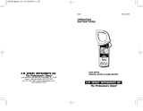
○Measurement categories (Over-voltage categories)
To ensure safe operation of measuring instruments, IEC61010 establishes
safety standards for various electrical environments, categorized as CATⅠto
CATⅣ, and called measurement categories. Higher-numbered categories
correspond to electrical environments with greater momentary energy, so a
measuring instrument designed for CATⅢenvironments can endure greater
momentary energy than one designed for CATⅡ.
CAT.Ⅰ: Secondary electrical circuits connected to an AC electrical outlet
through a transformer or similar device.
CAT.Ⅱ: Primary electrical circuits of equipment connected to an AC
electrical outlet by a power cord.
CAT.Ⅲ: Primary electrical circuits of the equipment connected directly to the
distribution panel, and feeders from the distribution panel to outlets.
CAT.Ⅳ: The circuit from the service drop to the service entrance, and to the
power meter and primary over-current protection device
(distribution panel).
2. FEATURES
●Digital clamp tester for AC leakage measurement.
●Least affected by external magnetic field, providing wide
measuring range from very small to large currents.
●Designed to safety standard IEC 61010-2-032: Measurement
category CAT.Ⅲ, 300V and pollution degree 2.
●Tear drop shaped jaws for ease of use in crowded cable areas
and other tight places.
●Data hold function to allow for easy readings in dimly lit or hard-to-
reach locations.
●Provides filtering function to remove high frequency generated by
such equipment as inverters.
●Peak hold function to allow for measurement of current variation
as short as 10msec.
●Auto-power-off function prevents unnecessary power consumption
●Dynamic range of 4000 counts full scale.
●Large easy-to-read LCD display with letter height of 13mm.
●Operation confirming beeps.
●Insulation barrier at the tip of transformer jaws for improved safety.
Incoming wire
CAT.Ⅳ
Interior wiring
Transformer
CAT.Ⅰ
CAT.Ⅱ
CAT.Ⅲ
ocket
3. SPECIFICATIONS
Measuring ranges and accuracy
Operating System: Sequential comparison
Display: LCD with max. reading of 3999 (MODEL
2432 & MODEL2433's 400A range), 6000
(MODEL2433's 40mA/400mA range)
Low battery warning: "BATT" mark appears on the display
Overrange Indication: "OL" appears on the display when upper limit
of measuring range is exceeded
Response Time: Approx. 2 seconds
Sample Rate: Approx. 2.5 times per second
Location for use: Indoor use, Altitude up to 2000m
Accuracy-insured 23℃±5℃, relative humidity 85% or less
Temperature and (without condensation)
Humidity Ranges:
Operating Temperature 0-40℃, relative humidity 85% or less
and Humidity Ranges: (without condensation)
Storage Temperature -20-60℃, relative humidity 85% or less
and Humidity Ranges: (without condensation)
Power Source: Two 1.5V R03 (UM-4) batteries
Current Consumption: Approx. 13mA
Measurement Time: Approx. 40 hours
Auto-power-off Function:Turns power off about 10 minutes after the
last switch operation
Safety Standard: IEC 61010-2-032
Measurement CAT.Ⅲ300V, pollution degree 2
IEC61326 (EMC)
Overload Protection: 2432: 120AAC max. for 10 seconds
2433: 480AAC max. for 10 seconds
Withstand Voltage: 3700VACrms (50/60Hz) for 1 minute between
metal part of transformer jaws and housing
case (except transformer jaw case)
Insulation Resistance: 10MΩ or greater at 1000V between metal
part of transformer jaws and housing case
(except transformer jaw case)
Conductor Size: Approx. 40mm in diameter max.
Dimensions: 185(L)×81(W)×32(D)mm
Weight: 2432: Approx. 290g including batteries
2433: Approx. 270g including batteries
Accessories: Two R03 (UM-4) batteries
Carrying case Model 9052
Instruction manual
Optional Accessories: Multi-Tran Model 8004 and 8008
When measuring current which pulse element is superposed, differences
of the indicated value may be caused between ranges, if the peak value
exceeds the measurement range to a large extent. In this case, the
reading at the bigger range should be taken as a right value.
Counts equal to or less than 5 counts are corrected to zero.
The max indication at the 40mA/400mA range on MODEL2433 is 6000
counts. Minute current may exist while zero is displayed at 400A/400mA
range. Measurement should be made also at a lower range.
Model
2432
2433
Range
4mA
40mA
100A
40mA
400mA
400A
Measuring Range
0~3.999mA
0~39.99mA
0~80.0A
~100.0A
0~39.9mA
0~399.9mA
0~350.0A
~399.9A
Accuracy (Frequency range)
±1.0%rdg±5dgt (50/60Hz)
±2.5%rdg±10dgt (20~1kHz)
±1.0%rdg±5dgt (50/60Hz)
±2.5%rdg±10dgt (40~1kHz)
±5.0%rdg (50/60Hz)
±10.0%rdg (40~1kHz)
±1.0%rdg±5dgt (50/60Hz)
±2.5%rdg±10dgt (20~1kHz)
±1.0%rdg±5dgt (50/60Hz)
±2.5%rdg±10dgt (40~1kHz)
±2.0%rdg (50/60Hz)
±5.0%rdg (40~1kHz)
4. INSTRUMENT LAYOUT
5. PREPARATIONS FOR MEASUREMENT
5-1 Checking Battery Voltage
Set the Range Selector Switch to any position other than the OFF
position. If the marks on the display is clearly visible without "BATT"
mark showing, battery voltage is OK. If the display blanks or "BATT"
is indicated, replace the batteries according to section 8: Battery
Replacement.
NOTE
When the instrument is left powered on, the auto-power-off
function automatically shut the power off; The display blanks even
if the Range Selector Switch is set to a position other than the
OFF position in this state. To power on the instrument, turn the
Range Selector Switch or press the Data Hold Button. If the
display still blanks, the batteries are completely exhausted.
Replace the batteries.
5-2 Checking Switch Setting
Make sure that the Range Selector Switch is set to the appropriate
range.
Also make sure that data hold function is not enabled. If
inappropriate range is selected, desired measurement cannot be
made.
Transform Jaws
Barrier
Trigger
Range Selector Switch
Hand Strap
Display
Frequency Selector Button
Peak Hold Button
Data Hold Button
●LCD
Low Battery Warning
Frequency Response :
Wide
Frequency Response :
50/60Hz
Data Hold Indication
Peak Hold Indication
Function
6. OPERATING INSTRUCTIONS
6-1 Current Measurement
DANGER
●In order to avoid possible shock hazard, never make measurement
on circuits having a potential of 300VAC or greater.
●The transformer jaws are made of metal and their tips are not
completely insulated. Be especially careful about the possible
shorting where the equipment under test has exposed metal parts.
●Never make measurement with the battery compartment cover
removed.
●When measuring current is 300A or more ( 400Hz or more ), be sure to
stop measurement within 5 minutes. Otherwise, transformer jaws may
heat to cause a fire or deformation of molded parts, which will degrade
insulation.
●Keep your fingers and hands behind the barrier during measurement.
CAUTION
●Take sufficient care to not to apply shock, vibration or
excessive force to the jaw tips. Otherwise, precisely adjusted
Transformer Jaw tips will be damaged.
●When a foreign substance is stuck in the jaw tips or they
cannot properly engage, the transformer jaws do not fully
close. In such a case, do not release the jaw trigger abruptly or
attempt to close the transformer jaws by applying external
force. Make sure that the jaws close by themselves after
removing the foreign substance or making them free to move.
●The maximum size of a conductor to be tested is 40mm in
diameter. Accurate measurement cannot be made on a
conductor larger than this, because the transformer jaws
cannot fully close.
●When measuring large current, the transformer jaws may buzz.
This has no effect on the instrument's performance or safety.
(1)Set the Range Selector Switch to the desired position. Current
to measure should be within the selected measuring range.
(2)Normal measurement (See Fig.1, 2):
Press the jaw trigger to open the transformer jaws and close
them over one conductor only. Measured current value is shown
on the display. Earth leakage current or small current that flows
through a grounded wire can also be measured by this method.
(3)Measuring out of balance leakage current (See Fig. 3):
Clamp onto all conductors except a grounded wire. Measured
current value is shown on the display.
Fig. 1 Load current Fig. 2 Earth leakage current
Load
Load
6-2 How to Use Frequency Selector Button
When high frequencies from such equipment as inverters are
present in the circuit under test, the instrument measures AC
current of not only 50Hz or 60Hz of fundamental frequency but also
of these high frequencies and harmonics.
To eliminate the effect of such high frequency noise and measure
AC current of 50Hz or 60Hz fundamental frequency, a "high-cut"
filter circuit in incorporated into the instrument which works when
"50/60Hz" frequency response is selected with the Frequency
Selector Button. Cut-off frequency of the "high-cut" filter is about
160Hz with attenuation characteristic of approx. -24dB/octave.
When the Frequency Selector Button is pressed, "50/60Hz" mark is
shown on the left side of the display. When the Frequency Selector
Button is pressed again, fequency response is switched to WIDE
with "WIDE" mark shown on the display.
Note:
Characteristic of -24dB/octiave means that signal magnitude
declines to about one sixteenth of that at the initial frequency when
frequency doubles. KEW SNAP 2432 and KEW SNAP 2433 have
the following two settings for the Frequency Selector Button.
WIDE (20Hz-): Permits measurement of currents of fundamental
frequencies as well as currents of high frequencies
generated by such equipment as inverters
50/60Hz (20-approx.160Hz): Filters out high frequency currents and
measures current of fundamental
frequency only
Fig. 3 Measuring out of balance leakage current
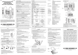
Fig.4 KEW SNAP 2432/2433 Frequency Characteristic
Output characteristic are shown in Fig.4.
100%
50%
20%
10%
5%
5k 1k 2k 500100 200502010
ー30
ー20
ー10
0
Attenuation〔dB〕
Percentage
Typical characteristic:
4/40/400mA Range
Typical characteristic:
“WIDE”frequency response
Typical characteristic:
“50/60Hz”frequency response
high-cut filter -24dB/oct
Typical characteristic:
100/400A Range
Load
Load
3-phase 3-wire system
(In 4-wire system with neutral,
clamp onto all 4 wires)
Single-phase 2-wire system
(in 3-wire system with neutral,
clamp onto all 3 wires)
Recently there has been increased use of power through inverters,
switching regulators, etc. When the high frequency noise from such
appliances leaks or flows into the ground through capacitors not
filtering completely, the earth leakage breaker may trip even though
there is no "actual" leakage. In such a case, the instrument do not
give leakage current reading if "50/60Hz" frequency response is
selected.
Take current readings with the 50/60Hz and WIDE frequency
responses respectively to make effective use of the Frequency
Selector Button.
6-3 Peak Current Measurement
(1)Set the Range Selector Switch to the desired position.(Current to
measure should not exceed the selected measuring range.)
(2)Select "WIDE"or "50/60Hz"with the Frequency Selector Button.
(3)With the transformer jaws clamped onto the conductor under
test, press the Peak Hold Button to set the interment to the peak
measurement mode.("P" is shown on the display.)
(4)The display reads 1/√2 of the peak current value. Therefore,an
rms reading is shown when current of a sinusoidal waveform is
measured.
(5)After peak measurement, press the Peak Hold Button to return to
the normal measurement mode.
Note: When leakage current is measured in the peak measurement
mode, the reading may change if the transformer jaws are
opened and closed. Please read the display with the conductor
under test clamped, otherwise, after fixing the display by using
the data hold function, please remove the instrument from the
conductor to be measured, and read the display. To measure
the peak current again, please release the data hold, and return
the instrument to the normal measurement mode once with the
Peak Hold Button, then set it in the peak measurement mode.
7. OTHER FUNCTIONS
7-1 Auto-Power-Off Function
This is a function to prevent the instrument from being left powered
on and conserve battery power. The instrument automatically turns
off about 10 minutes after the last switch or button operation. To
return to the normal mode, turn the Range Selector Switch to OFF,
then to the desired position.
Disabling Auto-Power-Off Function:
To disable the auto-power-off function, power on the instrument
with the Data Hold Button pressed. About 3 seconds after powering
on the instrument, "P.OFF" is shown on the display. To enable the
auto-power-off function, turn on the instrument without pressing the
Data Hold Button.
Note: The auto-power-off function is disabled in the peak
measurement mode.
7-2 Date Hold Function
This is a function to freeze the readings on the display. When the
Data Hold Button is pressed once, the current reading is held even
though current under test varies. "H" mark is shown on the upper
right corner of the display.
To exit the data hold mode, press the Data Hold Button again.
Note: When the auto-power-off function works while the instrument
is in the data hold mode, data hold is cancelled.
8. BATTERY REPLACEMENT
WARNING
In order to avoid possible shock hazard, always set the Range
Selector Switch to the OFF position before trying to replace the
batteries.
CAUTION
●Do not mix new and old batteries.
●Install batteries in the orientation as shown inside the battery
compartment, observing correct polarity.
When the battery voltage warning mark "BATT" is shown on the
top left corner of the LCD, replace the batteries. Note that the
display blanks and "BATT" mark is not shown if the batteries are
completely exhausted.
(1)Set the Range Selector Switch to "OFF."
(2)Loosen the battery-compartment-
cover-fixing screw on the lower
back of the instrument.
(3)Replace the batteries with two
new R03 (UM-4) 1.5V batteries.
(4)Put the battery compartment
cover back in place and tighten
the screw.
Note: For use for a long period of time,
use alkaline batteries.
9. OPTIONAL ACCESSORIES
Model 8004 and 8008 (Multi-Tran)
These models help KEW SNAP 2432 or
KEW SNAP 2433 to measure current greater
than 3000A or to make measurement on a
large bus-bar or conductor.
(1)Set the Range Selector Switch to
"100A" or "400A."
(2)As shown, open the jaws and close
them over the pickup coil of Model
8004 or Model 8008.
(3)Clamp on a conductor with Model
8004 or Model 8008.
(4)Take the reading and multiply it by
10.
Note: When used with Model 8008, KEW SNAP 2432 can measure up to
1000A.
Model 8004 and Model 8008 cannot be used for leakage current
measurement. For detailed specifications, refer to the instruction
manual for Model 8004 or Model 8008.
KEW SNAP 2432
KEW SNAP 2433
M-8004
M-8008
Pickup Coil
Conductor
Transformer
jaws
10
:
1
M-8004
M-8008
Max. Conductor Size
60mm in diameter
100mm in diameter
Measuring
Range
0~1000A
0~3000A
Current Transformation
Ratio
10:1
10:1
Screw Battery
Compartment
Cover
Batteries
92
―
1452H11
―
11
DISTRIBUTOR
Kyoritsu reserves the rights to change specifications or designs
described in this manual without notice and without obligations.
INSTRUCTION MANUAL
KEW SNAP 2432/2433
KEW SNAP Series
LEAKAGE CURRENT TESTER
KEW SNAP 2432
KEW SNAP 2433
KYORITSU ELECTRICAL INSTRUMENTS WORKS, LTD.,
TOKYO, JAPAN
1. SAFETY WARNINGS
This instrument has been designed and tested according to IEC
Publication 61010: Safety Requirements for Electronic Measuring
Apparatus. This instruction manual contains warnings and safety
rules which must be observed by the user to ensure safe operation
of the instrument and to retain it in safe condition. Therefore, read
through these operating instructions before starting using the
instrument.
WARNING
●Read through and understand instructions contained in this
manual before starting using the instrument.
●Save and keep the manual handy to enable quick reference
whenever necessary.
●Be sure to use the instrument only in its intended applications
and to follow measurement procedures described in the
manual.
●Be sure to understand and follow all safety instructions
contained in the manual.
Not following the above instructions may cause injury, instrument
damage and/or damage to equipment under test.
The symbol indicated on the instrument means that the user
must refer to related parts of the manual for safe operation of the
instrument. Be sure to carefully read the instructions following
each symbol in this manual.
DANGER is reserved for conditions and actions that are likely
to cause serious or fatal injury.
WARNING is reserved for conditions and actions that can
cause serious or fatal Injury.
CAUTION is reserved for conditions and actions that can
cause minor injury or Instrument damage.
Following symbols are used on the instrument and in the instruction
manual. Attention should be paid to each symbol to ensure your
safety.
Refer to the instructions in the manual.
This symbol is marked where the user must refer to the instruction
manual so as not to cause personal injury or instrument damage.
Indicates an instrument with double or reinforced insulation.
Indicates that this instrument can clamp on bare conductors when
measuring a voltage corresponding to the applicable Measurement
category, which is marked next to this symbol.
Indicates AC (Alternating Current).
DANGER
●Never make measurement on a circuit having potential of
300VAC or greater.
●Do not attempt to make measurement in the presence of
flammable gasses. Otherwise, the use of the instrument may
cause sparking, which leads to an explosion.
●The transformer jaws are made of metal and their tips are not
completely insulated. Be especially careful about the possible
shorting where the equipment under test has exposed metal parts.
●Never attempt to use the instrument if its surface or your hand is wet.
●Do not exceed the maximum allowable input of any
measurement range.
●Never open the battery compartment cover when making
measurement.
●Never try to make measurement if any abnormal conditions,
such as broken Transformer jaws or case is noted.
●The instrument is to be used only in its intended applications or
conditions. Otherwise,safety functions equipped with the
instrument doesn't work, and instrument damage or serious
personal injury may be caused.
WARNING
●Never attempt to make any measurement, if any abnormal
conditions are noted, such as broken case, cracked test leads
and exposed metal parts.
●Do not install substitute parts or make any modification to the
instrument. Return the instrument to Kyoritsu or your distributor
for repair or re-calibration.
●Do not try to replace the batteries if the surface of the
instrument is wet.
●Always switch off the instrument before opening the battery
compartment cover for battery replacement.
CAUTION
●Make sure that the range selector switch is set to an appropriate
position before making measurement.
●Do not expose the instrument to the direct sun, extreme
temperatures or dew fall.
●Be sure to set the range selector switch to the "OFF" position
after use. When the instrument will not be in use for a long
period of time, place it in storage after removing the batteries.
●Use a damp cloth and detergent for cleaning the instrument. Do
not use abrasives or solvents.
○Measurement categories (Over-voltage categories)
To ensure safe operation of measuring instruments, IEC61010 establishes
safety standards for various electrical environments, categorized as CATⅠto
CATⅣ, and called measurement categories. Higher-numbered categories
correspond to electrical environments with greater momentary energy, so a
measuring instrument designed for CATⅢenvironments can endure greater
momentary energy than one designed for CATⅡ.
CAT.Ⅰ: Secondary electrical circuits connected to an AC electrical outlet
through a transformer or similar device.
CAT.Ⅱ: Primary electrical circuits of equipment connected to an AC
electrical outlet by a power cord.
CAT.Ⅲ: Primary electrical circuits of the equipment connected directly to the
distribution panel, and feeders from the distribution panel to outlets.
CAT.Ⅳ: The circuit from the service drop to the service entrance, and to the
power meter and primary over-current protection device
(distribution panel).
2. FEATURES
●Digital clamp tester for AC leakage measurement.
●Least affected by external magnetic field, providing wide
measuring range from very small to large currents.
●Designed to safety standard IEC 61010-2-032: Measurement
category CAT.Ⅲ, 300V and pollution degree 2.
●Tear drop shaped jaws for ease of use in crowded cable areas
and other tight places.
●Data hold function to allow for easy readings in dimly lit or hard-to-
reach locations.
●Provides filtering function to remove high frequency generated by
such equipment as inverters.
●Peak hold function to allow for measurement of current variation
as short as 10msec.
●Auto-power-off function prevents unnecessary power consumption
●Dynamic range of 4000 counts full scale.
●Large easy-to-read LCD display with letter height of 13mm.
●Operation confirming beeps.
●Insulation barrier at the tip of transformer jaws for improved safety.
Incoming wire
CAT.Ⅳ
Interior wiring
Transformer
CAT.Ⅰ
CAT.Ⅱ
CAT.Ⅲ
t
3. SPECIFICATIONS
Measuring ranges and accuracy
Operating System: Sequential comparison
Display: LCD with max. reading of 3999 (MODEL
2432 & MODEL2433's 400A range), 6000
(MODEL2433's 40mA/400mA range)
Low battery warning: "BATT" mark appears on the display
Overrange Indication: "OL" appears on the display when upper limit
of measuring range is exceeded
Response Time: Approx. 2 seconds
Sample Rate: Approx. 2.5 times per second
Location for use: Indoor use, Altitude up to 2000m
Accuracy-insured 23℃±5℃, relative humidity 85% or less
Temperature and (without condensation)
Humidity Ranges:
Operating Temperature 0-40℃, relative humidity 85% or less
and Humidity Ranges: (without condensation)
Storage Temperature -20-60℃, relative humidity 85% or less
and Humidity Ranges: (without condensation)
Power Source: Two 1.5V R03 (UM-4) batteries
Current Consumption: Approx. 13mA
Measurement Time: Approx. 40 hours
Auto-power-off Function:Turns power off about 10 minutes after the
last switch operation
Safety Standard: IEC 61010-2-032
Measurement CAT.Ⅲ300V, pollution degree 2
IEC61326 (EMC)
Overload Protection: 2432: 120AAC max. for 10 seconds
2433: 480AAC max. for 10 seconds
Withstand Voltage: 3700VACrms (50/60Hz) for 1 minute between
metal part of transformer jaws and housing
case (except transformer jaw case)
Insulation Resistance: 10MΩ or greater at 1000V between metal
part of transformer jaws and housing case
(except transformer jaw case)
Conductor Size: Approx. 40mm in diameter max.
Dimensions: 185(L)×81(W)×32(D)mm
Weight: 2432: Approx. 290g including batteries
2433: Approx. 270g including batteries
Accessories: Two R03 (UM-4) batteries
Carrying case Model 9052
Instruction manual
Optional Accessories: Multi-Tran Model 8004 and 8008
When measuring current which pulse element is superposed, differences
of the indicated value may be caused between ranges, if the peak value
exceeds the measurement range to a large extent. In this case, the
reading at the bigger range should be taken as a right value.
Counts equal to or less than 5 counts are corrected to zero.
The max indication at the 40mA/400mA range on MODEL2433 is 6000
counts. Minute current may exist while zero is displayed at 400A/400mA
range. Measurement should be made also at a lower range.
Model
2432
2433
Range
4mA
40mA
100A
40mA
400mA
400A
Measuring Range
0~3.999mA
0~39.99mA
0~80.0A
~100.0A
0~39.9mA
0~399.9mA
0~350.0A
~399.9A
Accuracy (Frequency range)
±1.0%rdg±5dgt (50/60Hz)
±2.5%rdg±10dgt (20~1kHz)
±1.0%rdg±5dgt (50/60Hz)
±2.5%rdg±10dgt (40~1kHz)
±5.0%rdg (50/60Hz)
±10.0%rdg (40~1kHz)
±1.0%rdg±5dgt (50/60Hz)
±2.5%rdg±10dgt (20~1kHz)
±1.0%rdg±5dgt (50/60Hz)
±2.5%rdg±10dgt (40~1kHz)
±2.0%rdg (50/60Hz)
±5.0%rdg (40~1kHz)
4. INSTRUMENT LAYOUT
5. PREPARATIONS FOR MEASUREMENT
5-1 Checking Battery Voltage
Set the Range Selector Switch to any position other than the OFF
position. If the marks on the display is clearly visible without "BATT"
mark showing, battery voltage is OK. If the display blanks or "BATT"
is indicated, replace the batteries according to section 8: Battery
Replacement.
NOTE
When the instrument is left powered on, the auto-power-off
function automatically shut the power off; The display blanks even
if the Range Selector Switch is set to a position other than the
OFF position in this state. To power on the instrument, turn the
Range Selector Switch or press the Data Hold Button. If the
display still blanks, the batteries are completely exhausted.
Replace the batteries.
5-2 Checking Switch Setting
Make sure that the Range Selector Switch is set to the appropriate
range.
Also make sure that data hold function is not enabled. If
inappropriate range is selected, desired measurement cannot be
made.
Transform Jaws
Barrier
Trigger
Range Selector Switch
Hand Strap
Display
Frequency Selector Button
Peak Hold Button
Data Hold Button
●LCD
Low Battery Warning
Frequency Response :
Wide
Frequency Response :
50/60Hz
Data Hold Indication
Peak Hold Indication
Function
6. OPERATING INSTRUCTIONS
6-1 Current Measurement
DANGER
●In order to avoid possible shock hazard, never make measurement
on circuits having a potential of 300VAC or greater.
●The transformer jaws are made of metal and their tips are not
completely insulated. Be especially careful about the possible
shorting where the equipment under test has exposed metal parts.
●Never make measurement with the battery compartment cover
removed.
●When measuring current is 300A or more ( 400Hz or more ), be sure to
stop measurement within 5 minutes. Otherwise, transformer jaws may
heat to cause a fire or deformation of molded parts, which will degrade
insulation.
●Keep your fingers and hands behind the barrier during measurement.
CAUTION
●Take sufficient care to not to apply shock, vibration or
excessive force to the jaw tips. Otherwise, precisely adjusted
Transformer Jaw tips will be damaged.
●When a foreign substance is stuck in the jaw tips or they
cannot properly engage, the transformer jaws do not fully
close. In such a case, do not release the jaw trigger abruptly or
attempt to close the transformer jaws by applying external
force. Make sure that the jaws close by themselves after
removing the foreign substance or making them free to move.
●The maximum size of a conductor to be tested is 40mm in
diameter. Accurate measurement cannot be made on a
conductor larger than this, because the transformer jaws
cannot fully close.
●When measuring large current, the transformer jaws may buzz.
This has no effect on the instrument's performance or safety.
(1)Set the Range Selector Switch to the desired position. Current
to measure should be within the selected measuring range.
(2)Normal measurement (See Fig.1, 2):
Press the jaw trigger to open the transformer jaws and close
them over one conductor only. Measured current value is shown
on the display. Earth leakage current or small current that flows
through a grounded wire can also be measured by this method.
(3)Measuring out of balance leakage current (See Fig. 3):
Clamp onto all conductors except a grounded wire. Measured
current value is shown on the display.
Fig. 1 Load current Fig. 2 Earth leakage current
Load
Load
6-2 How to Use Frequency Selector Button
When high frequencies from such equipment as inverters are
present in the circuit under test, the instrument measures AC
current of not only 50Hz or 60Hz of fundamental frequency but also
of these high frequencies and harmonics.
To eliminate the effect of such high frequency noise and measure
AC current of 50Hz or 60Hz fundamental frequency, a "high-cut"
filter circuit in incorporated into the instrument which works when
"50/60Hz" frequency response is selected with the Frequency
Selector Button. Cut-off frequency of the "high-cut" filter is about
160Hz with attenuation characteristic of approx. -24dB/octave.
When the Frequency Selector Button is pressed, "50/60Hz" mark is
shown on the left side of the display. When the Frequency Selector
Button is pressed again, fequency response is switched to WIDE
with "WIDE" mark shown on the display.
Note:
Characteristic of -24dB/octiave means that signal magnitude
declines to about one sixteenth of that at the initial frequency when
frequency doubles. KEW SNAP 2432 and KEW SNAP 2433 have
the following two settings for the Frequency Selector Button.
WIDE (20Hz-): Permits measurement of currents of fundamental
frequencies as well as currents of high frequencies
generated by such equipment as inverters
50/60Hz (20-approx.160Hz): Filters out high frequency currents and
measures current of fundamental
frequency only
Fig. 3 Measuring out of balance leakage current
Fig.4 KEW SNAP 2432/2433 Frequency Characteristic
Output characteristic are shown in Fig.4.
100%
50%
20%
10%
5%
5k 1k 2k 500100 200502010
ー30
ー20
ー10
0
Attenuation〔dB〕
10
Frequency〔Hz〕
Percentage
Typical characteristic:
4/40/400mA Range
Typical characteristic:
“WIDE”frequency response
Typical characteristic:
“50/60Hz”frequency response
high-cut filter -24dB/oct
Typical characteristic:
100/400A Range
Load
Load
3-phase 3-wire system
(In 4-wire system with neutral,
clamp onto all 4 wires)
Single-phase 2-wire system
(in 3-wire system with neutral,
clamp onto all 3 wires)
Recently there has been increased use of power through inverters,
switching regulators, etc. When the high frequency noise from such
appliances leaks or flows into the ground through capacitors not
filtering completely, the earth leakage breaker may trip even though
there is no "actual" leakage. In such a case, the instrument do not
give leakage current reading if "50/60Hz" frequency response is
selected.
Take current readings with the 50/60Hz and WIDE frequency
responses respectively to make effective use of the Frequency
Selector Button.
6-3 Peak Current Measurement
(1)Set the Range Selector Switch to the desired position.(Current to
measure should not exceed the selected measuring range.)
(2)Select "WIDE"or "50/60Hz"with the Frequency Selector Button.
(3)With the transformer jaws clamped onto the conductor under
test, press the Peak Hold Button to set the interment to the peak
measurement mode.("P" is shown on the display.)
(4)The display reads 1/√2 of the peak current value. Therefore,an
rms reading is shown when current of a sinusoidal waveform is
measured.
(5)After peak measurement, press the Peak Hold Button to return to
the normal measurement mode.
Note: When leakage current is measured in the peak measurement
mode, the reading may change if the transformer jaws are
opened and closed. Please read the display with the conductor
under test clamped, otherwise, after fixing the display by using
the data hold function, please remove the instrument from the
conductor to be measured, and read the display. To measure
the peak current again, please release the data hold, and return
the instrument to the normal measurement mode once with the
Peak Hold Button, then set it in the peak measurement mode.
7. OTHER FUNCTIONS
7-1 Auto-Power-Off Function
This is a function to prevent the instrument from being left powered
on and conserve battery power. The instrument automatically turns
off about 10 minutes after the last switch or button operation. To
return to the normal mode, turn the Range Selector Switch to OFF,
then to the desired position.
Disabling Auto-Power-Off Function:
To disable the auto-power-off function, power on the instrument
with the Data Hold Button pressed. About 3 seconds after powering
on the instrument, "P.OFF" is shown on the display. To enable the
auto-power-off function, turn on the instrument without pressing the
Data Hold Button.
Note: The auto-power-off function is disabled in the peak
measurement mode.
7-2 Date Hold Function
This is a function to freeze the readings on the display. When the
Data Hold Button is pressed once, the current reading is held even
though current under test varies. "H" mark is shown on the upper
right corner of the display.
To exit the data hold mode, press the Data Hold Button again.
Note: When the auto-power-off function works while the instrument
is in the data hold mode, data hold is cancelled.
8. BATTERY REPLACEMENT
WARNING
In order to avoid possible shock hazard, always set the Range
Selector Switch to the OFF position before trying to replace the
batteries.
CAUTION
●Do not mix new and old batteries.
●Install batteries in the orientation as shown inside the battery
compartment, observing correct polarity.
When the battery voltage warning mark "BATT" is shown on the
top left corner of the LCD, replace the batteries. Note that the
display blanks and "BATT" mark is not shown if the batteries are
completely exhausted.
(1)Set the Range Selector Switch to "OFF."
(2)Loosen the battery-compartment-
cover-fixing screw on the lower
back of the instrument.
(3)Replace the batteries with two
new R03 (UM-4) 1.5V batteries.
(4)Put the battery compartment
cover back in place and tighten
the screw.
Note: For use for a long period of time,
use alkaline batteries.
9. OPTIONAL ACCESSORIES
Model 8004 and 8008 (Multi-Tran)
These models help KEW SNAP 2432 or
KEW SNAP 2433 to measure current greater
than 3000A or to make measurement on a
large bus-bar or conductor.
(1)Set the Range Selector Switch to
"100A" or "400A."
(2)As shown, open the jaws and close
them over the pickup coil of Model
8004 or Model 8008.
(3)Clamp on a conductor with Model
8004 or Model 8008.
(4)Take the reading and multiply it by
10.
Note: When used with Model 8008, KEW SNAP 2432 can measure up to
1000A.
Model 8004 and Model 8008 cannot be used for leakage current
measurement. For detailed specifications, refer to the instruction
manual for Model 8004 or Model 8008.
KEW SNAP 2432
KEW SNAP 2433
M-8004
M-8008
Pickup Coil
Conductor
Transformer
jaws
10
:
1
M-8004
M-8008
Max. Conductor Size
60mm in diameter
100mm in diameter
Measuring
Range
0~1000A
0~3000A
Current Transformation
Ratio
10:1
10:1
Screw Battery
Compartment
Cover
Batteries
92
―
1452H11
―
11
DISTRIBUTOR
Kyoritsu reserves the rights to change specifications or designs
described in this manual without notice and without obligations.
○Measurement Category:
To ensure safe operation of measuring instruments, IEC 61010 establishes
safety standards for various electrical environments, categorized as O to
CAT IV, and called measurement categories. Higher-numbered categories
correspond to electrical environments with greater momentary energy, so a
measuring instrument designed for CAT III environments can endure
greater momentary energy than one designed for CAT II.
O :
Circuits which are not directly connected to the mains power supply.
CAT II : Electrical circuits of equipment connected to an AC electrical outlet
by a power cord.
CAT III :
Primary electrical circuits of the equipment connected directly to the
distribution panel, and feeders from the distribution panel to outlets.
CAT IV : The circuit from the service drop to the service entrance, and to the
power meter and primary over-current protection device
(distribution panel).
Incoming wire
O:Device which is
not directly
connected to the
mains power supply
Socket
Interior wiring
3470 5 sec. between
92
-
1452
L
4
-
22
1. SAFETY WARNINGS
This instrument has been designed and tested according to IEC
Publication61010:SafetyRequirementsforElectronicMeasuring
Apparatus.Thisinstructionmanualcontainswarningsandsafety
ruleswhichmustbeobservedbytheusertoensuresafeoperation
of the instrument and to retain it in safe condition. Therefore,
readthroughtheseoperatinginstructionsbeforestartingusingthe
instrument.
#
WARNING
●Readthroughandunderstandinstructionscontainedinthis
manualbeforestartingusingtheinstrument.
●Save and keep the manual handy to enable quick reference
whenevernecessary.
●Theinstrumentistobeusedonlyinitsintendedapplications.
●Understandandfollowallthesafetyinstructionscontainedinthe
manual.
Failure to follow the instructions may cause injury, instrument
damageand/ordamagetoequipmentundertest.Kyoritsuisbyno
meansliable foranydamage resultingfrom theinstrument in
contradictiontothiscautionarynote.
Thesymbol
#
indicatedontheinstrumentmeansthattheusermust
refer to related parts ofthemanualforsafeoperation of the
instrument.Besuretocarefullyreadtheinstructionsfollowingeach
#
symbolinthismanual.
#
DANGER is reservedforconditions and actions that are likely
tocauseseriousorfatalinjury.
#
WARNINGisreservedforconditionsandactionsthatcancause
seriousorfatalInjury.
#
CAUTIONisreservedforconditionsandactionsthatcancause
minorinjuryorInstrumentdamage.
Following symbols are used on the instrument and in the instruction
manual.Attentionshouldbepaidtoeachsymboltoensureyoursafety.
#
Refertotheinstructionsinthemanual.
This symbol ismarkedwheretheuser must refertothe
instruction manualsoasnotto causepersonalinjuryor
instrumentdamage.
Indicatesaninstrumentwithdoubleorreinforcedinsulation.
Indicates thatthis instrument can clamp on bare conductors
when measuring a voltage corresponding to the applicable
Measurementcategory,whichismarkednexttothissymbol.
IndicatesAC(AlternatingCurrent).
This instrument satisfies the marking requirement defined in
the WEEE Directive (2002/96/EC). This symbol indicates
separatecollectionforelectricalandelectronicequipment.
#
DANGER
●Nevermakemeasurementonacircuithavingpotential of
300VACorgreater.
●Donotattempttomakemeasurementinthepresenceof
flammable gasses. Otherwise, the use of the instrument may
causesparking,whichleadstoanexplosion.
●Thetransformerjawsaremadeofmetal and theirtipsarenot
completelyinsulated.Beespecially carefulaboutthepossible
shortingwheretheequipmentundertesthasexposedmetalparts.
●Neverattempttousetheinstrumentifitssurfaceoryourhandiswet.
●
Donotexceedthemaximumallowableinputofanymeasurementrange.
●Neveropenthebatterycompartmentcoverwhenmaking
measurement.
●Nevertrytomakemeasurementifanyabnormalconditions,such
asbrokenTransformerjawsorcaseisnoted.
●Theinstrumentistobeusedonlyinitsintendedapplicationsor
conditions.Otherwise,safetyfunctionsequippedwith the
instrumentdoesn'twork,andinstrument damage or serious
personalinjurymaybecaused.
●
Keepyourfingersandhandsbehindthebarrierduringmeasurement.
#
WARNING
●Neverattempttomake anymeasurement,ifanyabnormal
conditions are noted, such as broken case, cracked test leads
andexposedmetalparts.
●Do not install substitute parts or make any modification to the
instrument.Return theinstrument toKyoritsuor yourdistributor
forrepairorre-calibration.
●Donottrytoreplacethebatteriesifthesurfaceoftheinstrument
iswet.
●Always switch off the instrument before opening the battery
compartmentcoverforbatteryreplacement.
#
CAUTION
●Makesurethattherangeselectorswitchissettoanappropriate
positionbeforemakingmeasurement.
●Donotexposetheinstrumenttothe direct sun,extreme
temperaturesordewfall.
●Be sure to set the range selector switch to the "OFF" position
after use. When the instrument will not be in use for a long
periodoftime,placeitinstorageafterremovingthebatteries.
●Useadampclothanddetergentforcleaningtheinstrument.Do
notuseabrasivesorsolvents.
●
Thisinstrumentisn'tdust&waterproofed.Keepawayfromdust
andwater.
MeasurementCAT Ⅲ300V,pollutiondegree2
IEC61326-1(EMC)
6-2HowtoUseFrequencySelectorButton
When high frequencies from such equipment as inverters are
present in the circuit under test, the instrument measures AC
currentof notonly 50Hz or60Hz offundamental frequency but
alsoofthesehighfrequenciesandharmonics.
Toeliminatetheeffectofsuchhighfrequencynoiseandmeasure
AC current of 50Hz or 60Hz fundamental frequency, a "Low
pass"filtercircuitinincorporatedintotheinstrumentwhichworks
when "50/60Hz"frequencyresponseisselected with the
FrequencySelector Button. Cut-offfrequency of the"Low pass"
filter is about 160Hz with attenuation characteristic of approx.
-24dB/octave.
WhentheFrequencySelectorButtonispressed,"50/60Hz"mark
is shown on the left side of the display. When the Frequency
SelectorButtonispressedagain,fequencyresponseisswitched
toWIDEwith"WIDE"markshownonthedisplay.
100%
50%
20%
10%
5%
5k1k 2k500100 200502010
ー30
ー20
ー10
0
Attenuation〔dB〕
10
Frequency〔Hz〕
Percentage
Typical characteristic:
4/40/400mA Range
Typical characteristic:
“WIDE”frequency response
Typical characteristic:
“50/60Hz”frequency response
Low pass filter -24dB/oct
Typical characteristic:
100/400A Range
Environmental standards:
EURoHSdirectivecompliant