Page is loading ...

Page 1
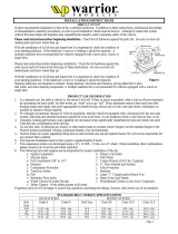
FIGURE #1
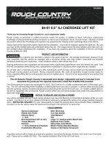
FIGURE #2
INSTALLATION INSTRUCTIONS
#30930 - 3” LIFT KIT – JEEP XJ
Warrior recommends this system be installed by a certified technician. In addition to these instructions, professional knowledge
of disassemble/re-assembly procedures as well as post installation checks must be known. Attempts to install this system
without this knowledge and expertise may jeopardize the integrity and/or operating safety of the vehicle.
Please read instructions before beginning installation. Check the kit hardware against the parts list. Be sure you have all
needed parts and know where they go.
With the installation of all lift kits and larger tires it is important to check the condition of your steering stabilizer. If the
stabilizer is worn or is leaking it should be replaced.. A multiple stabilizer kit is recommended for vehicles equipped with a
snow plow, winch, or larger tires
PRODUCT USE INFORMATION
As a general rule, the taller a vehicle is, the easier it will roll. To offset this tendency, increase your tire track width. In other
words, go "wide" as you go "tall". If you remove mud tires and install ones more appropriate for street driving; always use as
wide a tire and wheel combination as possible to enhance vehicle stability. We strongly recommend, because of rollover
possibility, that the vehicle be equipped with a functional roll-bar and cage system. Seat belts and shoulder harnesses should be
worn at all times. Avoid situations where a side rollover may occur. Generally, braking performance and capability are
decreased when significantly larger/heavier tires and wheels are used. Take this into consideration while driving.
Do not add, alter, or fabricate any factory or after-market parts to increase vehicle height over the intended height of the Warrior
product purchased. Mixing component brands is not recommended. Warrior makes no claims regarding lifting devices and
excludes any and all implied claims. We will not be responsible for any product that is altered. If questions exist we will be
happy to answer any questions concerning the design, function, and correct use of our products.
NOTICE TO DEALER AND VEHICLE OWNER
Any vehicle equipped with any Warrior product should have a “Warning to Driver” decal installed on the inside of the
windshield or dash. The decal informs whoever is operating the vehicle of its unique handling characteristics.
INSTALLING DEALER - It is your responsibility to install the warning decal and forward these installation instructions on to
the vehicle owner for review. These instructions should be kept in the vehicle for its service life.
COIL SPRING INSTALLATION INSTRUCTIONS
1. Place wheels in straight ahead position. Set parking brake and block both sides of rear wheels.
2. Jack up the vehicle and place the vehicle on jack stands.
3. Remove the front wheels and tires.
4. Support the axle with a floor jack.
5. Remove the stock shock absorbers. The bolt and nut on the bottom of the shock will be reused.
6. Unbolt the sway bar links on both sides. (See Figure #1)
7. Locate and remove the coil clip on the lower coil spring seat. Lower the axle to allow for
removal of the coil spring. Do not over extend the brake lines. The caliper can be removed from
the rotor to allow the axle to lower.
8. If needed , use a strut compressor to remove the coil springs.
9. Remove stock coil springs (See Figure #2)
10. Using a strut compressor, compress the new Warrior coil springs and install. Install coil spring
clip back onto the lower coil spring seat.
11. Attach sway bar end links to sway bar and tighten.
12. Install new Warrior shock absorbers.
13. Install wheels and tires.
14. Jack up the vehicle, remove the jack stands, and lower the vehicle to the ground.

INSTALLATION INSTRUCTIONS
Technical Assistance - (888) 220-6861 Page 2
ADD-A-LEAF INSTALLTION INSTRUCTIONS
Notes:
• If a torch is used during this installation, protect any heat-sensitive components located in the immediate area by covering
them with a water-saturated cloth. Most under coatings are flammable, but can be extinguished using a water filled spray
bottle. Have this and an ABC rated fire extinguisher at hand.
• Prior to inserting leafs, be sure all leaf “mating” surfaces are free of grit, grease, undercoating, etc.
• A factory service manual for this particular year and model should be on hand. The manual will contain fastener torque
specs and any assemble techniques or special tool requirements that are unique to this vehicle.
• Shock absorber length, depending on the particular vehicle, may not be adequate. Whatever the case, we highly recommend
the installation of a premium grade shock for optimum performance.
• Prior to disassembly, inspect the stock u-bolts for corrosion and adequate length.
Step 1. Put the vehicle in neutral, raise the vehicle and support with jack stands on the frame. For front installations, the
stands normally are placed just behind the springs rear hangers. For rear installations the stands are generally placed
just in front of the springs front hangers. Put vehicle in park, or low gear for manual transmissions, and chock the
tires remaining on the floor to prevent accidental movement.
Step 2. Remove the tires and position floor jack to support the axle. Remove the bottom shock bolts.
Step 3. Remove nuts/washers from the u-bolts on one side of the axle. If the straps or bend clips must be disturbed, do this
before removing spring eye-bolt. Have c-clamps in place on either side of each strap before center bolt is removed.
Step 4. Remove the spring eye bolts and nuts and remove the spring.
Step 5. Unbolt center pin and remove. Un-clamp the leaf spring. CAUTION - Take care when releasing the c-clamps
since the springs are under load and will “spring” apart when released.
Step 6. Position helper leaf under the next longest leaf of the spring pack. Replace the shorter spring leafs under the helper
leaf and clamp together, being careful to align the center-pin holes in the spring leafs.
Step 7. Insert the new center-pin supplied with the kit through the spring assembly with the head of the center-pin in the
same location as the stock pin. Re-compress the pack with the c-clamps, not the center-pin, to avoid stripping of
nut/bolt threads. Bolt together, being sure to align leafs. Cut off excess threads on the center pin with a hack saw.
If applicable, re-form straps or install new bend straps. If heat is used on the straps, allow them to cool naturally
and thoroughly before removing the c-clamps.
Step 8. Replace spring on vehicle and replace with new u-bolts, nuts and washers. Torque u-bolts evenly using a “x”
tightening sequence to the following values.
½” 65-80 ft/lbs
9/16” 75-90 ft/lbs.
5/8” 86-110 ft/lbs.
Do not fully tighten the stock shackle and stationery spring eye bolts. These bolts are not torqued until the
suspension is supporting the vehicle weight.
Step 9. Front only - Most models have a turning radius stop bolts located on the front axle knuckles. In a full locked turn
these stops limit turning before the tires make contact with the leaf springs or the steering sector itself is “bottomed
out”. Adjust, as needed, each stop bolt so it limits turning at least ½” before tire-to-spring contact occurs. Tire-to-
spring contact may cause tire damage and, in extreme cases, increase the possibility of vehicle rollover.
Step 10. Repeat the process for the other spring.
Step 11. Remove jack-stands and lower vehicle to floor. With the suspension supporting vehicle weight, torque the springs’
stationary and shackle eye-bolts.
Step 12. Alignment - On solid axle applications, alignment is not significantly altered by “add-a-leaf” lift. But, we suggest
that alignment be checked to assure correct tire wear and drive-ability.

INSTALLATION INSTRUCTIONS
Technical Assistance - (888) 220-6861 Page 3
POST INSTALLATION INSTRUCTIONS
1. Check all fasteners for proper torque. Check to ensure there is adequate clearance between all rotating, mobile, fixed and
heated members. Check steering gear for interference and proper working order. Test brake system.
2. Perform steering sweep. Check to ensure brake hoses have sufficient slack and will not contact rotating, mobile, or fixed
members, adjust lines/brackets to eliminate interference and maintain proper working order. Failure to perform inspections
may result in component failure.
3. Bump stops and extensions must be in place on all vehicles! Note: allowing suspension to over extend by neglecting to
install or maintain stops and extensions may cause serious damage to OE and related components.
4. Re torque all fasteners after 500 miles. Visually inspect components and re torque fasteners during routine vehicle service.
MAINTENANCE INFORMATION
It is the buyers responsibility to have all bolts/nuts checked for tightness after the first 100 miles. After that, check them every
1000 miles. Wheel alignment steering system, suspension and drive line systems must be inspected by a qualified professional
mechanic at least every 3000 miles.
PARTS LIST
Front Coil Spring Kit TJ/XJ Lower Control Arm XJ Rear Add-A-Leaf Kit
800026 800027 800025
Front Shocks TJ/XJ Front Sway Bar Bracket Kit Other
60504 (2) 800017 700005 Black Shck Boots(4)
700005 Black Cable Tie-(4)
Rear Shocks XJ Frnt Sway Bar Link Kit
60505 (2) 800015
/