Page is loading ...

06-510 S.R. SMITH, LLC 2006 JUN11
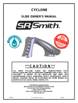
CYCLONE
CORPORATE HEADQUARTERS
WESTERN SALES AND MANUFACTURING PLANT
P.O. Box 400
•
1017 SW Berg Parkway
Canby, Oregon 97013
Phone: (503) 266-2231
•
Fax: (503) 266-4334
www.srsmith.com
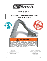
ASSEMBLY AND INSTALLATION
INSTRUCTIONS
* * C A U T I O N * *
S.R. SMITH CYCLONE SLIDES ARE MANUFACTU
RED FOR
INSTALLATION AND USE ON INGROUND SWIMMING POOLS ONLY. THE
CYCLONE IS NEVER TO BE INSTALLED AND USED ON ABOVEGROUND
POOLS, ONGROUND POOLS, HOUSEBOATS, BOAT DOCKS, FLOATING
DOCKS OR PLATFORMS OR OTHER BODIES OF WATER SUCH AS
LAKES, PONDS, RIVERS, ETC.

2
Table of Contents
Topic Page #
Introduction……………………………………………………………………………………… 2
Parts List………………………………………………………………………………………… 3
Gasket Placement……………………………………………………………………………… 4
Assembly Instructions…………………………………………………………………………. 5
Plumbing Installation………………………………………………………………………….. 6
On-Deck Mounting Instructions………………………………………………………………. 7
Manufacturer’s Placement Instructions……………………………………………………… 8
Installed Slides’ Structural & Installation Checklist………………………………………… 10
INTRODUCTION
The Cyclone slide is designed and manufactured for installation and use on inground swimming pools only.
Cyclone slides are NEVER to be installed and used on aboveground pools, onground pools, houseboats,
boat docks, floating docks or platforms, or other bodies of water such as lakes, ponds, rivers, etc. Proper
and complete assembly, use and supervision is essential for proper operation and to reduce the risk of
accident or injury.
**IMPORTANT**
Check entire boxes and inside all packing materials for parts. Before beginning assembly, read the
instructions and identify parts using the figures and parts listed in this document. It is critical that all
parts be carefully inspected by the installer prior to installation to ensure that no damage occurred in
transit and that a damaged part is not used. Proper installation cannot be overstressed, as an improper
installation voids S.R. Smith’s warranty and may affect the safety of the user.
FIG. 1

3
CYCLONE PARTS LIST
Tools Required:
1. Ratchet handle
2. 9/16” deep socket
3. 9/16” wrench
4. 1/2" socket or wrench
5. 1/2" concrete drill bit
6. 1/4" drill bit
7. Phillips screw driver
8. Power drill
9. Lint free rag
ITEM #
PART #
DESCRIPTION
QTY.
1
5-139
3/8” Hex Nut
2 ea.
2
5-151
3/8” Lock Washer
2 ea.
3
05-14-115
1/2" Lock Washer
7 ea.
4
5-145
3/8” Flat Washer
16 ea.
5
5-245
3/8” x 2-1/2” Lag Screw
10 ea.
6
5-240
3/8” x 3-1/2” Lag Screw
2 ea.
7
5-238
3/8” x 6” Hex Head Cap Screw
2 ea.
8
5-241
1/2"-13 Anchor 5.5" Long w/Nut & Washer
7 ea.
9
05-711
PVC Nipple SCH 80 ¾” x 2”
1 ea.
10
05-712
¾” FHT x ¾”FIPT Swivel 90
1 ea.
11
8-531
Gasket
2 ft.
12
5-371
Hose Clip Screw
1 ea.
13
05-713
¾” Hose Clip
1 ea.
(1)
(5)
(7)
(8)
(3)
(2)
(4)
(10)
(9)
(12)
(11)
(6)
(13)

4
If your gasket was factory installed, be
1. Clean the groove of the top runway section, shown below, with a damp
clean rag and dry.
2. Place the gasket.
a) Take the 2 feet of gasket provided with your kit and begin to peel
back the paper. Make sure you are not removing the adhesive itself
from the gasket.
b) Take the exposed gasket & adhesive and begin at a top edge of the
runway section groove.
c) While firmly pressing the gasket into the groove, intermittently press
and remove more paper, exposing adhesive, until you have used the
entire gasket.
d) Properly installed, the gasket will extend from one side of the slide to
the other and be centered in the groove, front to back.
e) Continue to assemble your Cyclone as described on page 5, and
ensure the gasket remains in place as you handle the sections.
Top Runway Section
(11)
1. Clean the groove
2. Place Gasket into Groove
**IMPORTANT**
Before assembling sections
Prepare your Cyclone for water
**IMPORTANT**
If your Gasket was factory installed, be sure to inspect it to the criteria
mentioned above in bullet “d, e”. Failure to ensure proper gasket placement
may result in leaking at slide seams.

5
ASSEMBLY INSTRUCTIONS
1. Place the upper & lower slide
runway sections on the ground.
Assemble and fasten as shown.
2. a. Attach the pedestal to the
upper & lower slide sections as
shown in (2) locations.
b. Attach the pedestal as shown
in (4) locations. Mark and drill a
1/4" pilot hole in the center of
each recess before fasting with
the lag screws.
3. Attach the assembled slide
runway to the ladder using the
hardware shown.
(4) (6)
(4)
(5)
(5)
(4)
(7)
(4)
(1)
(2)
b
a
(4) (5)

6
Plumbing Installation
1. Thread the nipple (9) into swivel (10).
2. Note the angle of the threaded hole in the top
runway section.
3. Align the nipple with the hole-angle from the
outside of the slide as shown in the top
illustration.
4. Insert the nipple into the slides hole and
firmly thread the nipple using the swivel (10)
to turn.
**This action is self sealing and no Teflon or
Plumbing glue is required**
5. Note the pressure required as you turn the
fitting assembly, this is letting you know a
tight fit is being formed.
**The fitting material is harder than the slide
material and makes its own threading; that is why
it is good to get this right the first time, but not
imperative**
6. Turn the fitting assembly (9 & 10) until the
swivel (10) comes in contact with the wall of
the Cyclone
7. Gently tilt the swivel (10) away from the slide
and complete one more turn to ensure a
good insertion.
8. Finish turning the swivel (10) with the fitting
assembly pointed back toward the bottom of
the stairs as shown in the bottom illustration.
**Threads still showing between the nipple (9)
and slide wall after step 8 (above) are better left
exposed than over tightening and stripping the
hole or scraping the slide wall with the swivel
(10)**
9. Place the hose clip in a location where it will
support the hose without putting a “kink” into
its shape; screw it directly into the slide stairs
making sure not to over tighten the screw.
**The purpose of the clip is to take shock
transferred through the hose from sudden jerks**
10. Turn on the water so that it lands in the
center of the slide runway and ENJOY!
Nipple (9)
Swivel (10)

7
ON-DECK MOUNTING INSTRUCTIONS
1. Place the assembled slide on the deck relative to the pool wall. Ensure that the exit flume clears any
coping. Slide may be angled slightly providing all dimensions are maintained as noted in the
Manufacturer’s Placement Instructions noted in the following section.
2. With the slide in its proper location, center punch or otherwise mark through the (7) mounting holes at
the bottom of the ladder and base so that a visible mark is apparent on the concrete.
3. Move the assembled slide aside to facilitate drilling of the anchoring holes.
4. Using a power drill and a 1/2” concrete drill bit, drill the holes to a depth of 4”. Use tape or a marking
on the drill bit to ensure that the hole for the anchor is drilled to the required depth. Maintain drill hole
straight and perpendicular for proper holding strength of anchor stud.
5. Clear the holes of all debris. Assemble anchor with nut and washer so that the top of the nut is flush
with the top of the anchor. Move the slide over the holes and insert the anchors. Drive anchor through
the slide mounting holes so that nut and washer are flush with the surface material.
6. Expand anchor by tightening nut 3 to 5 turns. Once anchor is set remove nut and install a lock washer,
item # (3), and retighten nut to a torque of 55 ft.-lbs.

8
MANUFACTURER’S PLACEMENT INSTRUCTIONS
1. The critical dimensions for placement of the CYCLONE are as shown in FIG.’S 2 and 3.
A. The slide exit runway surface shall not exceed twenty inches (20”) above the water surface as
shown in FIG. 2.
B. The slide shall be positioned so that all water flowing off the runway exit drops into the pool. The
recommended overhang is 4 inches.
C. The minimum depth of water below the exit lip of the slide shall be three feet (3’) and increase to
three feet six inches (3’-6”) at Pt. A, which is a distance of four feet six inches (4’-6”) from the exit lip
of the slide as shown in FIG. 2.
D. A minimum depth of three feet six inches (3’-6”) shall be maintained at a distance of nine feet (9’)
along the extended centerline of the slide from Pt. A. as shown in FIG. 2.
2. A minimum clearance area in front of the slide shall be maintained at all times as follows:
A. The minimum clearance distance on either side of the extended centerline of the slide runway shall
not be less than three feet six inches (3’-6”) at a point no less than two
feet six inches (2’-6”) from the exit lip of the slide and extending a
distance of thirteen feet six inches (13’-6”) in front of the slide as shown
in FIG. 3.
B. The minimum clearance area in front of a properly installed diving board
on an inground swimming pool is a minimum distance of three feet six
inches (3’-6”) on either side of the board’s centerline as shown in FIG.
4. Pt. C extends a minimum distance of “C” from the tip end of the
board as shown in FIG. 4. The width distance “W” on either side of Pt.
C is given in CHART 1 and shown in FIG. 4.
FIG. 2
FIG. 3
DECK/COPING SURFACE
3' MIN.
EXIT
RUNWAY SURFACE
PLUMBLINE
20" MAX.
WATER LEVEL
ENTRANCE
Pt.A
13'-6" MIN.
9' MIN. 4'-6"
3'-6" MIN.3'-6" MIN.

9
“C” DIMENSION FOR BOARD = AB + BC
“W” DIMENSION FOR BOARD = WIDTH AT PT.C
C. The minimum clearance area of a slide or diving board shall not intersect any coping or rope and
float line as shown in FIG. 5. The minimum clearance area of a slide or diving board may intersect
each other provided that they are not used simultaneously.
CHART 1
BOARD MINIMUM CLEARANCE AREA
POOL TYPE
“C” DIMENSION
“W” DIMENSION
I
14’-6”
5’-0”
II
14’-6”
6’-0”
III
16’-6”
6’-0”
IV
18’-6”
7’-6”
V
21’-0”
7’-6”
See Article 5 contained in ANSI/APSP/ICC-5 2011
STANDARD FOR RESIDENTIAL INGROUND SWIMMING
POOLS and refer to FIGURE 3 and Table 1 for Minimum
Water Envelope Dimensions AB, BC and Width at Point C.
FIG. 5
FIG. 4

10
INSTALLED CYCLONE STRUCTURAL & INSTALLATION CHECKLIST
1. Inspect the runway for visible cracks or tears.
2. Inspect the ladder for sharp edges, protrusions, cracks or tears.
3. Inspect all fasteners to make sure they are fully tightened.
4. Inspect the ladder for rigidity and attachment.
5. Measure the following dimensions and compare with the Manufacturer’s Placement Instructions on
pages 6 and 7.
• Measure the depth of water in front of the slide exit. (3’-6” min. depth at a distance of 4’-6”
from exit end of slide.)
• Measure the height of the slide runway exit above the water. (20” max.)
• Measure the distance between the slide centerline and the edge of other pool equipment.
6. Observe the position of the exit of the slide as shown in FIG.’S 2, 3 and 5 on pages 6 and 7.
IMPORTANT
PERSONALLY GIVE TO SLIDE OWNER THE CYCLONE OWNER’S MANUAL, THE
WARRANTY CARD AND ANSWER ALL QUESTIONS.
/