Page is loading ...

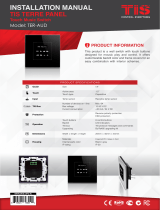
This product is a BUS-operated wall panel with
touch buttons for smart control over lights, curtains,
indoor climate, appliances, and preset scenarios.
This switch is remotely conrollable and applicable
in various types of buildings.
PRODUCT INFORMATION
6 58921 79722 8
BARCODE (UPC-A)
INSTALLATION MANUAL
LUNA BEDSIDE PANEL
Bedside Touch Panel
MODEL: LUNA-BEDSIDE
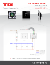
PRODUCT SPECIFICATIONS
OLED Size 0.9”
Touch Active area 4.3”
Touch type Capacitive
Input
Temp sensor Resistive temp sensor
IR receiver TIS infrared code receiver
Using panel addition 2-3 Digital input
Output
Using panel addition 3R 3 Relay output 3A/5A
Using panel addition 3DL-12V 12V DC 50mA output
Using panel addition 2DL-IRE IR Emitter
TIS Bus
Number of devices on 1 line Max. 64
Bus voltage 12-32 V DC
Current consumption <45 mA / 24 V DC
Operation
Touch buttons 12 buttons for AC / lights / moods
Backlight 12 RGB indicators
TIS bus TIS Protocol messages and commands
Upgrading By Rs485 upgrading kit
Functions
1 Press ON / OFF / Scene / AC control
Long press Dim or ramp the lights
Double click Extra Scene
IR receiver Music, scene, lights control
Dimensions Width × length × height 94mm × 129mm × 13mm
Housing
Materials Fireproof PC / Glass in front
Casing color Silver plating frame. Glass white or black
Internal parts color Black & White
IP rating IP 50

INSTALLATION MANUAL
MODEL: LUNA-BEDSIDE
Luna Bedside PaneL
2
www.tiscontrol.com
TIS CONTROL LIMITED
Wanchai, Hong Kong
TIS CONTROL PTY LIMITED
SA , AUSTRALIA
Copyright © 2022 TIS, All Rights Reserved
TIS Logo is registered trademark of TIS CONTROL.
All of the specification are subject to change without notice.
Data Cable
Use screened stranded RS485 data cable
with four twisted pairs. Congure devices in
a “Daisy Chain.”
Do not cut or terminate live data cables.
Electrical Wires
The recommended wire size for light
channels is 1.5mm - 2.5mm for loads, if you
are using the Panel Addition 3R type. The
installer should consider the total current
consumption when selecting the wires.
Warranty
There is a two-year warranty provided
by law. The hologram warranty seal and
product serial number are available on
each device.
Read Instructions
We recommend that you read this
Instruction Manual before installation.
Safety instructions
Electrical equipment should only be
installed and tted by electrically skilled
persons.
Failure to follow the instructions may cause
damage to the device and other hazards.
These instructions are an integral part of
the product and must remain with the end
customer.
Programming
This device can be tested and programmed
manually. Advanced programming
requires knowledge of the TIS Device
Search software and instruction in the TIS
advanced training courses.
Simple Installation
You can use 2 screws to install this panel
on wall; it ts on most junction box sizes.
Mounting Location
Install in a dry, indoor area. with a suitable
temperature and humidity range.

INSTALLATION MANUAL
MODEL: LUNA-BEDSIDE
Luna Bedside PaneL
3
www.tiscontrol.com
TIS CONTROL LIMITED
Wanchai, Hong Kong
TIS CONTROL PTY LIMITED
SA , AUSTRALIA
Copyright © 2022 TIS, All Rights Reserved
TIS Logo is registered trademark of TIS CONTROL.
All of the specification are subject to change without notice.
Insert a large athead screwdriver in
the hole of the Panel Cover. Rotate the
screwdriver 90 degrees.
1
INSTALLATION STEPS
2Separate the Cover, Main Panel, and
Wall Base from each other.

INSTALLATION MANUAL
MODEL: LUNA-BEDSIDE
Luna Bedside PaneL
4
www.tiscontrol.com
TIS CONTROL LIMITED
Wanchai, Hong Kong
TIS CONTROL PTY LIMITED
SA , AUSTRALIA
Copyright © 2022 TIS, All Rights Reserved
TIS Logo is registered trademark of TIS CONTROL.
All of the specification are subject to change without notice.
Remove the 2 screws on the Panel
Addition cover.
3
INSTALLATION STEPS
4
Smart Home
Smart Home
Connect the Wall Base and Panel
Addition in this position. Place the upper
pins as shown, and then push the down
pins down with your ngers to assemble.

INSTALLATION MANUAL
MODEL: LUNA-BEDSIDE
Luna Bedside PaneL
5
www.tiscontrol.com
TIS CONTROL LIMITED
Wanchai, Hong Kong
TIS CONTROL PTY LIMITED
SA , AUSTRALIA
Copyright © 2022 TIS, All Rights Reserved
TIS Logo is registered trademark of TIS CONTROL.
All of the specification are subject to change without notice.
It should look like this following the
correct assembly.
INSTALLATION STEPS
5
6
Turn off the main electrical source before
installation.
Connect the Cat5e TIS BUS wire to the
Panel Addition.
GND(white-orange)&(white-brown)
D-(white-green)&(white-blue)
D+(blue-green)
+24V(brown-orange)
Cat5e connection
PANEL ADDITION
2 Digital Input with IR Emitter
Model : ADD-2DL-IRE
TIS BUS Input : 45mA/24V DC
IR- IR+ DNG Z2 Z1
www.tissmarthome.com
D- +24V
GND D+
TV
Cat5e
to the TIS BUS Network
WARNING! HIGH VOLTAGE

INSTALLATION MANUAL
MODEL: LUNA-BEDSIDE
Luna Bedside PaneL
6
www.tiscontrol.com
TIS CONTROL LIMITED
Wanchai, Hong Kong
TIS CONTROL PTY LIMITED
SA , AUSTRALIA
Copyright © 2022 TIS, All Rights Reserved
TIS Logo is registered trademark of TIS CONTROL.
All of the specification are subject to change without notice.
GND(white-orange)&(white-brown)
D-(white-green)&(white-blue)
D+(blue-green)
+24V(brown-orange)
Cat5e connection
low voltage cable
low voltage cable
low voltage cable
PANEL ADDITION
2 Digital Input with IR Receiver
Model : ADD-2DL-IRR
TIS BUS Input : 45mA/24V DC
VCC REC DNG Z2 Z1
www.tissmarthome.com
D- +24V
GND D+
TIS IR Receiver probe
Luna Bed Side
TV
Cat5e
to the TIS BUS Network
INSTALLATION STEPS
7Connect the other connection if needed as per the panel addition type.
FOR PANEL ADDITION 2DL-IRR
You can connect 2 digital inputs to any
switch or window magnet.
You can add an External Infrared Receiver
to the IRR Port, connect as follows:
▸
the IR Receiver black wire to GND
▸
Gray wire to REC
▸
Red wire to VCC Terminal.
PANEL ADDITION
2 Digital Input with IR Receiver
Model : ADD-2DL-IRR
TIS BUS Input : 45mA/24V DC
VCC REC GND Z2 Z1
www.tissmarthome.com
D- +24V
GND D+
To the TIS BUS Network
Cat5e
GND(white-orange)&(white-brown)
D-(white-green)&(white-blue)
D+(blue-green)
+24V(brown-orange)
Cat5e connection
low voltage cable
low voltage cable
Traditional Switch
L
S2
S1
S1
L
L
S2

INSTALLATION MANUAL
MODEL: LUNA-BEDSIDE
Luna Bedside PaneL
7
www.tiscontrol.com
TIS CONTROL LIMITED
Wanchai, Hong Kong
TIS CONTROL PTY LIMITED
SA , AUSTRALIA
Copyright © 2022 TIS, All Rights Reserved
TIS Logo is registered trademark of TIS CONTROL.
All of the specification are subject to change without notice.
PANEL ADDITION
2 Digital Input with IR Emitter
Model : ADD-2DL-IRE
TIS BUS Input : 45mA/24V DC
IR- IR+ DNG Z2 Z1
www.tissmarthome.com
D- +24V
GND D+
TIS IR Emitter probe
Luna Bed Side
GND(white-orange)&(white-brown)
D-(white-green)&(white-blue)
Cat5e connection
+24V(brown-orange)
D+(blue-green)
low voltage cable
low voltage cable
TV
Cat5e
to the TIS BUS Network
GND(white-orange)&(white-brown)
D-(white-green)&(white-blue)
D+(blue-green)
+24V(brown-orange)
Cat5e connection
low voltage cable
low voltage cable
PANEL ADDITION
2 Digital Input with IR Emitter
Model : ADD-2DL-IRE
TIS BUS Input : 45mA/24V DC
IR- IR+ DNG Z2 Z1
www.tissmarthome.com
D- +24V
GND D+
Door Magnet Contact
Luna Bed Side
TV
Cat5e
to the TIS BUS Network
INSTALLATION STEPS
FOR PANEL ADDITION 2DL-IRE
You can connect 2 digital inputs to any
switch or window magnet.
▸
Connect the IR Emitter Probe’s positive
wire to IR+ terminal.
▸
Connect the negative wire to IR-terminal.

INSTALLATION MANUAL
MODEL: LUNA-BEDSIDE
Luna Bedside PaneL
8
www.tiscontrol.com
TIS CONTROL LIMITED
Wanchai, Hong Kong
TIS CONTROL PTY LIMITED
SA , AUSTRALIA
Copyright © 2022 TIS, All Rights Reserved
TIS Logo is registered trademark of TIS CONTROL.
All of the specification are subject to change without notice.
GND(white-orange)&(white-brown)
D-(white-green)&(white-blue)
D+(blue-green)
+24V(brown-orange)
Cat5e connection
low voltage cable
low voltage cable
low voltage cable
PANEL ADDITION
3 Digital Input with 12V Output
Model : ADD-3DL-12V
TIS BUS Input : 45mA/24V DC
Output: DC 12V/50mA
12V+ GND Z3 Z2 Z1
www.tissmarthome.com
D- +24V
GND D+
Luna Bed Side
C5
C2
PULSE
1&2
2&3
NONE
1P
2P
3P
RELAY
1&2
2&3
NO
NC
1 2 3
RELAY
1&2
2&3
NO
NC
1 2 3
TAMPER
ALARM
12V GND
CON1
1 2 3
LED1
818-6B V2.3
2016-11-09
3rd party sensor
TV
Cat5e
to the TIS BUS Network
GND(white-orange)&(white-brown)
D-(white-green)&(white-blue)
D+(blue-green)
+24V(brown-orange)
Cat5e connection
low voltage cable
low voltage cable
Door Magnet Contact
PANEL ADDITION
3 Digital Input with 12V Output
Model : ADD-3DL-12V
TIS BUS Input : 45mA/24V DC
Output: DC 12V/50mA
12V+ GND Z3 Z2 Z1
www.tissmarthome.com
D- +24V
GND D+
Luna Bed Side
TV
Cat5e
to the TIS BUS Network
INSTALLATION STEPS
FOR PANEL ADDITION 3DL-12V
You can connect 3 digital inputs to any
switch or window magnet.
Also, you can connect any 12V operated
smoke detector or any 3rd party sensor
with NC/NO connection to the 12V GND
and Z1-Z3 terminals as per the diagram.

INSTALLATION MANUAL
MODEL: LUNA-BEDSIDE
Luna Bedside PaneL
9
www.tiscontrol.com
TIS CONTROL LIMITED
Wanchai, Hong Kong
TIS CONTROL PTY LIMITED
SA , AUSTRALIA
Copyright © 2022 TIS, All Rights Reserved
TIS Logo is registered trademark of TIS CONTROL.
All of the specification are subject to change without notice.
GND(white-orange)&(white-brown)
D-(white-green)&(white-blue)
D+(blue-green)
24+V(brown-orange)
Cat5e connection
1.5 mm Electric Cable
1.5 mm Electric Cable
2.5 mm Electric Cable
Connect To L
O-OFF
I-ON
MCB
Open
Close
220 ~ 110
Volt
Connect To N
PANEL ADDITION
3 Output Relay 5 Amp
Model : ADD3-R5-A
TIS BUS Input : 75-45mA/24V DC
Output Current : 3A220VAC
COM OUT3 OUT2 OUT1 COM
www.tissmarthome.com
D- 24+V
GND D+
Cat5e
to the TIS BUS Network
O-OFF
I-ON
MCB
GND(white-orange)&(white-brown)
D-(white-green)&(white-blue)
D+(blue-green)
+24V(brown-orange)
Cat5e connection
1.5 mm Electric Cable
1.5 mm Electric Cable
2.5 mm Electric Cable
Connect To L
Connect To N
PANEL ADDITION
3 Output Relay 5 Amp
Model : ADD-3R-5A
TIS BUS Input : 45-75mA/24V DC
Output Current : 3A220VAC
COM OUT3 OUT2 OUT1 COM
www.tissmarthome.com
D- +24V
GND D+
Luna Bed Side
TV
Cat5e
to the TIS BUS Network
INSTALLATION STEPS
LIGHTING CONNECTION
▸
Connect the live wire to COM
▸
Connect the loads wire to Out1-Out3
to terminals
▸
Connect load neutral wire to main
neutral in the distributor box.
SHUTTER / CURTAIN CONNECTION
▸
Connect the Supply wire to COM
▸
Connect the Open wire to OUT1
▸
Connect the Close wire to OUT2
▸
Shutter neutral connection, if it exists,
can be looped to main neutral in the
distributor box.
FOR PANEL ADDITION 3R-5A
WARNING: Set the curtain function in the
software before connecting the wires.

INSTALLATION MANUAL
MODEL: LUNA-BEDSIDE
Luna Bedside PaneL
10
www.tiscontrol.com
TIS CONTROL LIMITED
Wanchai, Hong Kong
TIS CONTROL PTY LIMITED
SA , AUSTRALIA
Copyright © 2022 TIS, All Rights Reserved
TIS Logo is registered trademark of TIS CONTROL.
All of the specification are subject to change without notice.
1.5 mm Electric Cable
2.5 mm Electric Cable
GND(white-orange)&(white-brown)
D-(white-green)&(white-blue)
D+(blue-green)
+24V(brown-orange)
Cat5e connection
COOL
HEAT
FAN
COM
PANEL ADDITION
3 Output Relay 5 Amp
Model : ADD-3R-5A
TIS BUS Input : 45-75mA/24V DC
Output Current : 3A220VAC
COM OUT3OUT2 OUT1 COM
www.tissmarthome.com
D- +24V
GND D+
To the TIS BUS Network
Cat5e
GND(white-orange)&(white-brown)
D-(white-green)&(white-blue)
D+(blue-green)
24+V(brown-orange)
Cat5e connection
1.5 mm Electric Cable
1.5 mm Electric Cable
2.5
mm Electric Cable
PANEL ADDITION
3 Output Relay 5 Amp
Model : ADD3-R5-A
TIS BUS Input : 75-45mA/24V DC
Output Current : 3A220VAC
COM OUT3 OUT2 OUT1 COM
www.tissmarthome.com
D- 24+V
GND D+
Connect To L
O-OFF
I-ON
MCB
LOW
MEDIUM
HIGH
Luna Bedside
Cat5e
to the TIS BUS Network
INSTALLATION STEPS
FCU CONNECTION
▸
Connect the supply wire to com
▸
Connect the FAN Low, Medium, and
High wires to Out1, Out2, and Out3 in
the same order.
HVAC CONNECTION
▸
Connect the HVAC COM (supply)
wire to COM
▸
Connect the Cool, Heat, and FAN
wires to Out1, Out2, and Out3 in the
same order.
FOR PANEL ADDITION 3R-5A
WARNING: Set the FCU function in the
software before connecting the wires.
WARNING: Set the HVAC function in the
software before connecting the wires.

INSTALLATION MANUAL
MODEL: LUNA-BEDSIDE
Luna Bedside PaneL
11
www.tiscontrol.com
TIS CONTROL LIMITED
Wanchai, Hong Kong
TIS CONTROL PTY LIMITED
SA , AUSTRALIA
Copyright © 2022 TIS, All Rights Reserved
TIS Logo is registered trademark of TIS CONTROL.
All of the specification are subject to change without notice.
1.5 mm Electric Cable
1.5 mm Electric Cable
O-OFF
I-ON
MCB
Connect To L
Connect To N
TIS AIR BUS Convertor
Model NO : TIS-AIR-BUS-3W
AC Input : 100~240 V AC
www.tissmarthome.com
TIS AIR
TIS BUS Output : 100mA/12 V DC
D- +24V
GND D+
N L
Mount the device on the wall using 2
screws on the junction box.
8
INSTALLATION STEPS
FOR PANEL ADDITION AIR-BUS-3W
▸
Connect the live wire to the L terminal,
▸
Connect the neutral wire to N terminal.

INSTALLATION MANUAL
MODEL: LUNA-BEDSIDE
Luna Bedside PaneL
12
www.tiscontrol.com
TIS CONTROL LIMITED
Wanchai, Hong Kong
TIS CONTROL PTY LIMITED
SA , AUSTRALIA
Copyright © 2022 TIS, All Rights Reserved
TIS Logo is registered trademark of TIS CONTROL.
All of the specification are subject to change without notice.
Connect the main Luna panel vertically
to the part installed on the wall; install the
upper part by making sure the buckles
are completely inside.
10
Using your ngers, pull the protective
plastic cover vertically, remove it, and
throw it away.
9
INSTALLATION STEPS

INSTALLATION MANUAL
MODEL: LUNA-BEDSIDE
Luna Bedside PaneL
13
www.tiscontrol.com
TIS CONTROL LIMITED
Wanchai, Hong Kong
TIS CONTROL PTY LIMITED
SA , AUSTRALIA
Copyright © 2022 TIS, All Rights Reserved
TIS Logo is registered trademark of TIS CONTROL.
All of the specification are subject to change without notice.
A
18
35
COOL
OUT
Push on the bottom part of the main
panel to x it to the wall and complete the
assembly.
Turn on the power source. The panel
should turn ON.
11
12
INSTALLATION STEPS

INSTALLATION MANUAL
MODEL: LUNA-BEDSIDE
Luna Bedside PaneL
14
www.tiscontrol.com
TIS CONTROL LIMITED
Wanchai, Hong Kong
TIS CONTROL PTY LIMITED
SA , AUSTRALIA
Copyright © 2022 TIS, All Rights Reserved
TIS Logo is registered trademark of TIS CONTROL.
All of the specification are subject to change without notice.
PAIRING (MANUAL PROGRAMMING)
LIGHTS / SHUTTERS PROGRAMMING
You can pair the light channels with any wall panel. To do so, follow these steps:
RCU80-UT8-IN WARNING! HIGH VOLTAGE!
TIS-BUS
GND D- D+ 24+V
PRG
1 2 3 4 5 678
1 2 3 4 5 678
-+
8
7
GND
6
54
32
10-0V
DIGITAL INPUT
GND
1
1Press any button on any channel of a
relay or dimmer module for 6 seconds so
that the LED indicator light of that button
starts blinking.
6”
Shortly press on any lights or scene
button on wall panel or press the wall
switch that connected to dry inputs of the
panel addition zones.
2
A18
35
COOL
OUT
A18
35
COOL
OUT
Test the button on the panel by short
pressing it for ON/OFF and long pressing
it to dim (if channel is dimmable).
3

INSTALLATION MANUAL
MODEL: LUNA-BEDSIDE
Luna Bedside PaneL
15
www.tiscontrol.com
TIS CONTROL LIMITED
Wanchai, Hong Kong
TIS CONTROL PTY LIMITED
SA , AUSTRALIA
Copyright © 2022 TIS, All Rights Reserved
TIS Logo is registered trademark of TIS CONTROL.
All of the specification are subject to change without notice.
GND(white-orange)&(white-brown)
D-(white-green)&(white-blue)
D+(blue-green)
+24V(brown-orange)
Cat5e connection
1/L 2/M 3/H 4/L 5/M 6/H 7/L 8/M
1/L 2/M
TIS-BUS
GND D- D+ +24V
PRG
9/H 10/L 11/M 12/H
3/H
4/L 5/M 7/L 8/M 10/L 11/M
6/H 9/H 12/H
A B CD
VLC-12CH-10A WARNING! HIGH VOLTAGE!
To the TIS BUS Network
Cat5e
PAIRING (MANUAL PROGRAMMING)
FCU PROGRAMMING
1To program the FCU to any wall
thermostat panel, press and hold the rst
Channel L (LOW) button for 6 seconds.
The LED indicator of the pressed button
will start blinking,
6”
On the Luna bedside panel, turn the AC
ON.
2
A
18
35
COOL
OUT
A
18
35
COOL
OUT
Test your air conditioning by changing the
fan speed from low to medium to high.
Your relay should respond accordingly.
3

INSTALLATION MANUAL
MODEL: LUNA-BEDSIDE
Luna Bedside PaneL
16
www.tiscontrol.com
TIS CONTROL LIMITED
Wanchai, Hong Kong
TIS CONTROL PTY LIMITED
SA , AUSTRALIA
Copyright © 2022 TIS, All Rights Reserved
TIS Logo is registered trademark of TIS CONTROL.
All of the specification are subject to change without notice.
PAIRING (MANUAL PROGRAMMING)
HVAC PROGRAMMING
1Press the PRG button of the HVAC
Module for 6 seconds until the green LED
turns on and is steady.
On Luna bedside panel, turn the AC ON.
2
Test your air conditioning by changing
the mood, Heat/Cool, and fan speed from
low to medium to high. HVAC module
should respond accordingly.
3
HVAC6-3-A-T
Low Med
Cool Heat
PRG
TIS-BUS
GND D+ +24V
D-
High
AUX
MODE FAN
TEMP
VAV
GND 0-10V T- T+
Com Cool Heat Aux Low Med High
Com
6”
A
18
35
COOL
OUT
A
18
35
COOL
OUT

INSTALLATION MANUAL
MODEL: LUNA-BEDSIDE
Luna Bedside PaneL
17
www.tiscontrol.com
TIS CONTROL LIMITED
Wanchai, Hong Kong
TIS CONTROL PTY LIMITED
SA , AUSTRALIA
Copyright © 2022 TIS, All Rights Reserved
TIS Logo is registered trademark of TIS CONTROL.
All of the specification are subject to change without notice.
PAIRING (MANUAL PROGRAMMING)
FLOOR HEATING PROGRAMMING
1Press any button on any channel of a
relay or dimmer module for 6 seconds so
that the LED indicator light of that button
starts blinking.
On Luna bedside oor heater page, turn
the oor heating ON.
2
Test your oor heating by changing
the temperature, relay should respond
accordingly.
3
GND(white-orange)&(white-brown)
D-(white-green)&(white-blue)
D+(blue-green)
+24V(brown-orange)
Cat5e connection
1/L 2/M 3/H 4/L 5/M 6/H 7/L 8/M
1/L 2/M
TIS-BUS
GND D- D+ +24V
PRG
9/H 10/L 11/M 12/H
3/H
4/L 5/M 7/L 8/M 10/L 11/M
6/H 9/H 12/H
A B CD
VLC-12CH-10A WARNING! HIGH VOLTAGE!
To the TIS BUS Network
Cat5e
6”
Floor
25
10
OUT
Floor
25
10
OUT

INSTALLATION MANUAL
MODEL: LUNA-BEDSIDE
Luna Bedside PaneL
18
www.tiscontrol.com
TIS CONTROL LIMITED
Wanchai, Hong Kong
TIS CONTROL PTY LIMITED
SA , AUSTRALIA
Copyright © 2022 TIS, All Rights Reserved
TIS Logo is registered trademark of TIS CONTROL.
All of the specification are subject to change without notice.
PAIRING (MANUAL PROGRAMMING)
SCENARIO PROGRAMMING
The last row of the panel (buttons 5-8) can be programmed as mood (scene) that can save
the other 4 buttons’ and AC statuses
You can program the scene to save panel lights and shutter as one scene. Also, you can
add air condition to your scene.
TO PROGRAM THE LIGHTS/SHUTTER SCENE ONLY
Set the rst row (buttons 1-4) to lights ON/
OFF, dim brightness, and shutter status,
as per your preferred mood (scene).
Long press any button from 5-8 for 12
seconds until its LED blinks RED.
1
2
Floor
25
10
OUT
Floor
25
10
OUT
12”
The scene is programmed on the pressed
button; you can test it with a single press.
2
Floor
25
10
OUT

INSTALLATION MANUAL
MODEL: LUNA-BEDSIDE
Luna Bedside PaneL
19
www.tiscontrol.com
TIS CONTROL LIMITED
Wanchai, Hong Kong
TIS CONTROL PTY LIMITED
SA , AUSTRALIA
Copyright © 2022 TIS, All Rights Reserved
TIS Logo is registered trademark of TIS CONTROL.
All of the specification are subject to change without notice.
PAIRING (MANUAL PROGRAMMING)
TO PROGRAM THE LIGHTS/SHUTTER, AIR CONDITIONING
& FLOOR HEATING SETTING IN THE SCENE
Set the rst row (buttons 1-4) to lights ON/
OFF, dim brightness, and shutter status,
as per your preferred mood (scene).
Set your AC and oor heating desired
mode and temperature.
1
2
A
18
35
COOL
OUT
Floor
25
10
OUT
Long press any button from 5-8 for 16
seconds until its LED blinks BLUE.
3
A
18
35
COOL
OUT
16”
The scene is programmed on the pressed
button; you can test it with a single press.
4
Floor
25
10
OUT

INSTALLATION MANUAL
MODEL: LUNA-BEDSIDE
Luna Bedside PaneL
20
www.tiscontrol.com
TIS CONTROL LIMITED
Wanchai, Hong Kong
TIS CONTROL PTY LIMITED
SA , AUSTRALIA
Copyright © 2022 TIS, All Rights Reserved
TIS Logo is registered trademark of TIS CONTROL.
All of the specification are subject to change without notice.
A
18
35
COOL
OUT
A
18
35
COOL
OUT
USER MANUAL
You can use the panel buttons 1-8; press on any button to get the settings that you
programmed.
USING THE PANEL BUTTONS 1-8
▸
Short press for ON/OFF or to run a
scene.
▸
Double click to trigger a special
programmed scene.
▸
You can enable or disable the white
backlight, and you can set the LED
status color from blue to red.
▸
Long press to dim or ramp up the lights.
×2
A
18
35
COOL
OUT
/