Page is loading ...

DANGER
Danger of explosion. Do not use this product for storing or
transporting flammables, explosives, hazardous materials,
or hazardous waste, such as containers of gasoline, solvents,
gun powder, dynamite, propane tanks, acetylene tanks and
cutting torches. This product is only intended and safe for
use in storing and transporting small tools, equipment and
other similar materials. Any modifications made to, or unin-
tended use of this product, could create a hazardous condi-
tion that can cause death, serious personal injury or property
damage.
ASSEMBLY AND INSTALLATION INSTRUCTIONS
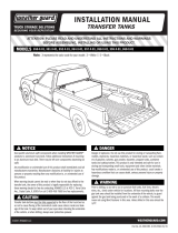
ITEMIZER® Aluminum Drawer Units
Models 314 • 316 • 317 • 318 • 326 • 327 • 328
Part No. 24-0300 REV. E ECN 5315 05/13
Figure 1. Aluminum Drawer
Units Shown Stacked
IMPORTANT
BEFORE YOU BEGIN
Read these instructions and
warnings completely before
installation.
TOOLS REQUIRED
• Drill with 5/16" & 13/32" drill bits
• 7/16" Open or Box End Wrench (2)
• 9/16" Open or Box End Wrench
BOLT KIT
Bolt Kit #32-0314 is provided with
your Drawer Unit. Check this bolt
kit to be sure the following parts
are included:
Quan. Description
6 1/4-20 x 3/4" Hex Hd. Bolt
4 1/4-20 Blind Fasteners
10 1/4" Flat Washers
6 1/4" Lock Washer, ext. tooth
1 1/4-20 x 2-1/4" Bolt, blk. ox.
1 Installation Tool
4 1/4-20 Nylon Lock Nuts
PARTS LIST
1- Drawer Unit
2- Mounting Brackets
6- Dividers (per drawer section)
Approximate Assembly and
Installation Time:
48 min. per unit (0.8 hrs.)
Depending on Van equipment
installation experience.
1

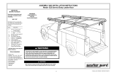
INSTALLATION INSTRUCTIONS
1. Position the lower Drawer Unit in the vehicle, making sure the obround holes in the
front skids are on top of the floor ribs (as shown in Figure 2.). Mark the floor through
the obround holes.
2. Go to the rear of the drawer unit (see Figure 3.) and place the Mounting Brackets,
as shown, with the longest side against the top of the floor rib. Mark through both sets
of holes to the floor and the rear skid.
3. Remove the drawer unit, drill the marked locations floor ribs for installation of four Blind
Fasteners. Follow Blind Fasteners installation instructions listed on the back page.
4. Drill the marked locations in the rear skid. Install the Mounting Bracket to the rear
skid.
5. Replace the drawer unit into the vehicle and fasten.
STACKING INSTRUCTIONS
6. Place the upper Drawer Unit on top of the previously installed lower unit. Align with the
front of the lower unit (see Figure 2.). Mark through the front skid obround holes to the
lower unit.
7. Move the rear of the unit (see Figure 3) and place the long end of the Mounting
Bracket into the open end of the rear skid. With the short end facing down, mark through
the hole to the side of the lower unit.
8. Remove the upper drawer unit and drill the rear holes in the side of the lower unit. Drill
the front skid holes and install Blind Fasteners.
9. Replace the upper unit and fasten.
WARNING
All floor mounting bolts near the gas tank area
should be installed from the underside of the
vehicle, to guard against the gas tank being
punc-tured in the event of a collision. This
would mean not using Blind Fasteners in this
area. Holes drilled in this area should be 5/16".
WARNING
CAUTION
To keep debris out of your eyes when checking
the underside of the vehicle, or when drilling,
always wear protective eyewear.
Prior to drilling, so as not to cut or puncture
fuel tanks, fuel lines, brake lines, electric wires,
etc., check under vehicle for locations.
Figure 3. Rear Mounting
1/4-20 Blind
Fastener
1/4-20 x 3/4"
Hex Hd. Bolt
1/4" External Tooth
Lock Washer
1/4" Flat
Washer
1/4-20 x 3/4"
Hex Hd. Bolt
1/4" External Tooth
Lock Washer
1/4" Flat
Washer
13/32" Hole
13/32" Hole
1/4" External Tooth
Lock Washer
Mounting
Bracket
1/4-20 Blind Fastener
13/32" Hole
5/16" Hole
1/4" Flat
Washer
1/4-20 x 3/4"
Hex Hd. Bolt
1/4" Flat
Washer
1/4-20 x 3/4"
Hex Hd. Bolt
1/4" External Tooth Lock Washer
1/4" Flat Washer
1/4-20 Nut
1/4" External Tooth Lock Washer
1/4-20 x 3/4"
Hex Hd. Bolt
1/4" Flat Washer
Mounting
Bracket
1/4-20 Blind Fastener
13/32"
Hole
Figure 2. Front Mounting
2

If you have any questions, please give us a call. Call Toll Free 1-800-456-7865
WEATHER GUARD® products are protected by one or more of the following trademarks:
U.S. - 842268, 1661625, 1663369, 1734659, 2228051, 2362167; Canada - 282725; U.K. - 1400720; N.Z. - 296049; Aus. - 761964
KNAACK LLC
420 E. TERRA COTTA AVENUE - CRYSTAL LAKE, ILLINOIS, USA 60014
815-459-6020
©2001 Knaack LLC
-NOTICE-
Any modification or unintended use of this product shall immediately void all manufacturers warranties.
Manufacturer disclaims all liability for injuries to persons or property resulting from any modification to, or
unintended use of this product.
WARNING
Prior to drilling, so as not to
cut or puncture fuel tanks, fuel
lines, brake lines, electric
wires, etc., check under vehi-
cle for locations.
NOTE - Be careful when drilling, or in-
stalling Blind Fastener, to ensure that
there is enough clearance behind the
surface so as not to damage the outer
skin of the vehicle, roof members or
vehicle components.
Black
Oxide
Bolt
Flat
Washer
9/16”
Wrench
Installation
Tool
Blind
Fastener
INSTALLATION PROCEDURE
USING BLIND FASTENERS
Place a drop of oil on the black oxide
bolt before assembling as shown on
right. Place the Blind Fastener in the
hole and use a 1/2” or 7/16” wrench to
tighten black hex bolt until the blind
fastener is fully seated. When setting
black hex bolt, it will start out hard.
As the Blind Fastener “bulbs” out it
will get easier, until it bottoms out or
sets. Make sure the Blind Fastener
and Installation Tool do not turn during
installation.
3
Part No. 24-0300 REV. E ECN 5315 05/13
/