Rev-A-Shelf 5743-04-CR-1 Operating instructions

Type
Operating instructions
INSTALLATION INSTRUCTIONS: 5300/5700 SERIES PULLOUT PANTRY
12400 Earl Jones Way
Louisville, KY 40299
rev-a-shelf.com
Customer Service: 800-626-1126
5300/5700 SERIES PULLOUT PANTRY
TOOLS REQUIRED:
60-90 MIN
ESTIMATED ASSEMBLY TIME:
CARE AND MAINTENANCE:
Clean with a damp cloth and
wipe parts dry.
I-5700-0617
表面處理
產品名稱
單位
:mm
繪圖日期
出圖檔名及路徑
零件名稱
零件編號
頁次 /
Y:\3D\Inventor\OEM\RAS\HA-RAS\RAS-HAHBHCHD系列-共用件.idw
2012/4/3
版本
46
第三角法
佳飾美國際事業有限公司
程 仁 勇
程 仁 勇
2
3
不可彎曲變形及刮痕
.
毛邊
Y:\3D\Inventor\OEM\RAS\HA-RAS\HA-RAS-500深系列\T&牛軛(名稱以變 )\H005.iam
檔案名稱及路徑
1
產品編號
HA\HB\HC\HD
46
製造流程
材料規格
委製廠商
V23
H005
高昇櫃
#5
模具編號
#4
#3
模具名稱
#1
#2
Parts List
No. Description Qty
1 Steel Frame 1
2 Wire Baskets 4-6
2 Solid Bottom Baskets 4-6
3 Top Slide 1
4 Bottom Slide 1
5 T-Type Door Brackets 2
6 4” T-Type Door Brackets * 2
7 Door Brackets 1-2
8 4” Door Brackets * 1-2
9 4mm Allen Wrench 1
10 #8 1/2” Wood Screws 20
11 #3/16 1” Wood Screws 4
12 M6 Screws 2
13 #8 1” Wood Screws 24
14 Solid Bottom Tray Cover Caps 4
15 Washers 2
16 M4 Screws 4
17 Logo Cap 1
18 Slide Feet 3
19 Plastic Basket Clips 8-12
1
2
7
9
3
or
4
5
6
8
12
15
17
19
10
13
16
18
11
14
1
8
#2
VIDEO INSTRUCTIONS: WWW.REV-A-SHELF.COM/VIDEOS
* 4” wide units only
Customer Service: 800-626-1126 | rev-a-shelf.com
2
Remove the soft-close
mechanism as shown in Figure
1A. Attach the slide feet to the
bottom of the slide using (4)
M4 screws (See Fig. 1B).
NOTE: You will need to
remove the inner member(s)
from the slide so you have
a hollow channel when
attaching the feet.
STEP 1
Place the Bottom Slide
Template in the bottom of your
cabinet as shown in Figure
2A. Mark (12) hole locations
as shown on the template and
drill 1/8” pilot holes. Align the
front of the slide with the front
of the face frame and center
the slide in the cabinet. Attach
to the oor using (8) #8 1”
wood screws (See Fig. 2B).
NOTE: When using the
template to align the pilot
holes, be sure to fold along
the dotted line on the front
of the template to wrap over
the face frame or front end
of the frameless cabinet. This
will keep your slide from
being installed too far back
into the cabinet.
STEP 2
The top slide of the pantry
needs to be mounted ush
with the face frame. To do
so, it may be necessary to cut
and attach a spacer board as
shown in Figure 3.
STEP 3
FIGURE 1A FIGURE 1B
FIGURE 2A
FIGURE 3
(A)
MEASURE FACE
FRAME WIDTH
CORRESPONDING SPACER
BOARD DIMENSIONS
AT LEAST 8”
(B)
MEASURE
CABINET
DEPTH
(A)
(B)
(A)
MEASURE FACE
FRAME WIDTH
CORRESPONDING SPACER
BOARD DIMENSIONS
AT LEAST 8”
(B)
MEASURE
CABINET
DEPTH
(A)
(B)
FACE FRAME CABINETS
Install bottom slide
1) Attach feet (#9) to bottom slide (C) using M4 screw (#8) as shown
in
eb ot deen lliw esolc-tfos eht ,toof raer eht hcatta oT .1
to remove the inner member(s) from the slide so you have a hollow
channel when attaching the feet.
Install top slide
3) The top slide (B) of the pantry needs to be mounted with the
draob recaps a hcatta dna tuc ot yrassecen eb ylekil lliw tI .emarf ecaf
as shown in
3.
Insert pantry frame
5) The bottom of the frame (A) sits on top of the bottom slide (C) as
shown in
.hcatta ot )3#( rehsaw dna )2#( wercs 6M esU .5
6) Slide the top portion of the frame up so that the top slide is
concealed but not touching the wood cabinet.
7) Two pins in top slide (B) insert into mating bushings in the top of
the frame (A) as shown in
6.
8) Tighten the two screws in 7.
C
B
B A
3
Top Spacer
Must be
with Face Frame
4) Using 4, mark 3 hole locations and drill pilot holes.
Roughly align the front of the slide with the front of the face frame
morf draob recaps eht ot hcattA .tenibac eht ni edils eht retnec dna
step 3 using screws (#6).
2) Mark 12 hole locations and drill eht ngila ylhguoR .seloh tolip
front of the slide with the front of the face frame and center the slide
eht ot hcattA .tenibac eht ni
using screws (#7). When using the
template to align the pilot hole, be sure to fold across the dotted line
on the front of the template to wrap over the face frame or front end
of the frameless cabinet. This will keep your slide from being installed
too far back into the cabinet. See
2.
A
C
A
C
(25)
(60)
(120)
(60)
(60)
(190)
(160)
(160)
(40)
UNIT : inch (mm)
1
8
#2
FIGURE 2B
CENTERLINE
cutting line for small cabinet
FRONT SIDE
(DOOR)
IJģ
ĩijĶĪ
ijĮĴİĹģ
ĩķıĪ
IJĮĴİĴijģ
ĩijĹĪ
ĵĮĴİĵģ
ĩIJijıĪ
ijĮĴİĹģ
ĩķıĪ
ĸĮIJİijģ
ĩIJĺıĪ
ijĮĴİĹģ
ĩķıĪ
5300/5700 SERIES PULLOUT PANTRY BOTTOM SLIDE TEMPLATE
12400 Earl Jones Way
Louisville, KY 40299
rev-a-shelf.com
Customer Service: 800-626-1126
T-5700-BTM-0117
INSTALLATION INSTRUCTIONS: 5300/5700 SERIES PULLOUT PANTRY 3
Tape the Top Slide Template
to your pantry ceiling (See Fig.
4A). Mark the (3) indicated hole
locations on the template and
drill 1/8” pilot holes. Align the
front of the slide with the front
of the face frame and center
the slide in the cabinet. Attach
to top of cabinet or to the
spacer board from Step 3 using
(3) #8 1/2” wood screws
(See Fig. 4B).
STEP 5
The bottom of the steel frame
sits on top of the bottom slide
as shown in Figure 5. Use (2)
M6 screws and accompanying
washers to attach the frame to
the bottom slide.
STEP 6
Re-attach the soft-close
mechanism.
STEP 4
Slide the top portion of the
frame up so that the top slide
is concealed and the (2) pins
in the top slide insert into the
(2) bushings in the top of the
frame as shown in Figure 6.
NOTE: The frame should not
touch the cabinet.
STEP 7
FIGURE 4A
FIGURE 5
FIGURE 6
FIGURE 4B
#2
1
8
IJĮĺİIJķģ
ĩĵıĪ
ķĮĶİIJķģ
ĩIJķıĪ
ķĮĶİIJķģ
ĩIJķıĪ
CENTERLINE
FRONT SIDE
(DOOR)
cutting line for small cabinet
5300/5700 SERIES PULLOUT PANTRY TOP SLIDE TEMPLATE
12400 Earl Jones Way
Louisville, KY 40299
rev-a-shelf.com
Customer Service: 800-626-1126
T-5700-TOP-0117
Customer Service: 800-626-1126 | rev-a-shelf.com
4
Cycle the unit fully a few times
before tightening the (2)
screws as shown in Figure 7.
STEP 8
To attach the T-Type door
bracket to the top and bottom
pantry, remove the center
screw (See Fig. 8A), insert the
T-Type bracket and connect the
T-Type bracket to the top of the
frame with the center screw.
Tighten this screw but note that
nal door adjustments will be
made later.
Repeat for the bottom bracket
(See Fig. 8B).
STEP 9
FIGURE 7
FIGURE 8A
FIGURE 8B
#2
4”wide unit shown
4”wide unit shown
INSTALLATION INSTRUCTIONS: 5300/5700 SERIES PULLOUT PANTRY 5
To determine the door
mounting position, rst
calculate the overlay. Refer to
Figure 9 for more direction.
NOTE: Overlay is the door
width minus the cabinet
opening width, divided by
2. For example, if a door is
12-1/2” wide, and the cabinet
opening is 12” wide:
12-1/2 - 12 = 1/2
1/2 divided by 2 = 1/4
The overlay = 1/4”
Finding Measurement “B”
Lay your door on a at surface
and mark (6) or (8) pilot hole
locations based on Figure 9.
Dimension “B” for a face frame
cabinet is 4-1/4”. Use an 1/8”
drill bit to pre-drill holes.
STEP 10
FIGURE 9
-
-
(57)
A
D
B
Use table to nd dimensions “C” and “D”
Finding Measurement “A”
Locate your stiles
(Note: Screws need to be installed
into the thick portion of your door
to prevent splitting) Adjust the top
T-Type door mount brackets so they
will hit the mounting screws in this
dimension
8" 10" 14" 16" 20"
A 7.87[200] 9.84[250] 13.86[352] 15.87[403] 19.88[505]
B 7.09[180] 9.06[230] 13.07[332] 15.08[383] 19.09[485]
C 8.82[244] 10.97[274] 13.82[351] 16.81[427] 20.83[529]
D 11.1[282] 13.07[332] 16.1[409] 19.09[485] 23.11[587]
B = Center to Center
A = Outside to Outside
C = Min. Bracket to Bracket
D = Max. Bracket to Bracket
B C
D
5743 4” [102 mm] + overlay N/A N/A
5750 4” [102 mm] + overlay 20-7/8” [530 mm] N/A
5758 4” [102 mm] + overlay 20-7/8” [530 mm] 20-7/8” [530 mm]
5773 4” [102 mm] + overlay 20-7/8” [530 mm] 25-3/16” [640 mm]
1
8
Customer Service: 800-626-1126 | rev-a-shelf.com
6
FIGURE 12
The next adjustment is the left
and right position of the door.
Loosen the (2) indicated screws
on each T-Type door bracket.
Slide the door left to right so
that the overlay is the same
on both sides. Tighten both
screws on each bracket. Once
this adjustment is nal, use (2)
#8 1” wood screws to lock the
door in place (See Fig 12).
STEP 13
FIGURE 10A FIGURE 10B
FIGURE 11
FIGURE 10C
Drive (2) M6 screws into only
the top (2) pilot holes (See
Fig. 10A). Position the door
so the screws t into the
T-Type door mount bracket
(See Figure 10B). Making sure
the door is oriented correctly,
and using (2) #8 1/2” wood
screws, fasten the bottom door
mount bracket to the door and
tighten top screws (See Fig.
10C).
STEP 11
Make the nal door
adjustments. By tightening
the front screw and loosening
the back screw, the door will
tilt left. By loosening the front
screw and tightening the back
screw, the door will tilt right.
Once the door is adjusted
correctly, tighten the center
screw both on top and bottom.
Now snap on the logo cap to
cover this hardware (See Fig.
11).
STEP 12
#2
INSTALLATION INSTRUCTIONS: 5300/5700 SERIES PULLOUT PANTRY 7
Attach the remaining door
mount bracket(s) (See Fig 14A).
The pilot holes drilled in step
10 should align. Figure 14B is
for 4” wide units only.
NOTE: Invert U bracket to
lock the door into place.
Install the top basket clip rst.
Position the basket clip inside
the frame and hold it to the
top. Snap the basket clips onto
the frame (See Fig 15). Slide
the basket down on the clips.
Conrm the desired spacing
between the baskets and
repeat for all remaining clips
and baskets.
STEP 16
FIGURE 13
FIGURE 15
The nal adjustment is top to
bottom tilt. Loosen the (2) M6
screws. Using the 4mm Allen
wrench, tighten the front screw
and loosen the back screw to
tilt the top of the door out.
For the top of the door to tilt
in towards the cabinet, loosen
the front screw and tighten
the back screw. To adjust the
whole door downward, tighten
both screws the same amount.
Finish by tightening the (2) M6
screws (See Fig 13).
STEP 14
STEP 15
FIGURE 14A
FIGURE 14B
#2
* 4” wide units only
9
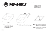
Quite el mecanismo de cierre suave
como se muestra en la gura 1A.
Sujete el pie del deslizante a la parte
inferior del deslizante, usando 4
tornillos M4 (ver la gura 1B).
NOTA: Usted necesitará quitar el
miembro(s) interno del deslizante
para que tenga un canal hueco cuando
sujete el pie.
Retirez le mécanisme de fermeture
en douceur comme indiqué sur
l’Illustration 1A. Fixez les pieds de
la coulisse au bas de la coulisse en
utilisant 4 vis M4 (voir l’Illustration 1B).
REMARQUE: Vous devrez retirer les
pièces internes de la coulisse pour que
vous disposiez d’un canal creux quand
vous attachez les pieds.
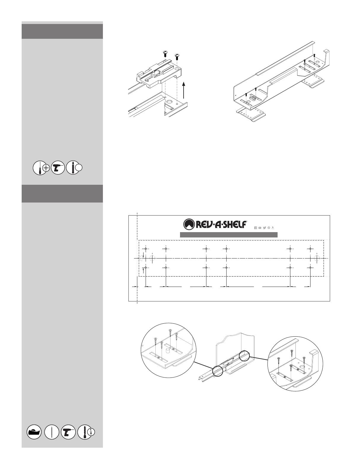
Coloque la Plantilla del Deslizante
Inferior en la parte inferior del
gabinete como se muestra en la gura
2A. Marque 12 ubicaciones de oricios
como se muestra en la plantilla y
taladre oricios piloto de 1/8”. Alineé
el frente del deslizante con el frente
del marco y centre el deslizante en el
gabinete. Sujete al piso, utilizando 8
tornillos de madera del #8 1” (ver la
gura 2B).
NOTA: Cuando esté usando la plantilla
para alinear los oricios piloto,
asegúrese de doblar a través de la
línea punteada en el frente de la
plantilla para envolver el marco o el
frente nal del gabinete sin marco.
Esto evitará que la plantilla sea
instalada demasiado lejos dentro del
gabinete.
Placez le modèle de la coulisse du
bas au bas de votre armoire comme
indiqué sur l’Illustration 2A. Marquez
les 12 emplacements des trous comme
indiqué sur le modèle et percez des
trous pilotes de 1/8 po. Alignez l’avant
de la coulisse avec l’avant du cadrage
avant et centrez la coulisse dans
l’armoire. Fixez au sol avec 8 vis à bois
#8 1 po (voir l’Illustration 2B).
REMARQUE: Lorsque vous utilisez le
modèle pour aligner les trous pilotes,
assurez-vous de plier le long de la
ligne en pointillé sur l’avant du modèle
pour envelopper autour du cadrage
avant ou de l’extrémité avant de
l’armoire sans cadre. Cela empêchera
votre coulisse d’être installée trop loin
dans l’armoire.
FIGURE 1A FIGURE 1B
FIGURE 2A
FACE FRAME CABINETS
Install bottom slide
1) Attach feet (#9) to bottom slide (C) using M4 screw (#8) as shown
in
eb ot deen lliw esolc-tfos eht ,toof raer eht hcatta oT .1
to remove the inner member(s) from the slide so you have a hollow
channel when attaching the feet.
Install top slide
3) The top slide (B) of the pantry needs to be mounted with the
draob recaps a hcatta dna tuc ot yrassecen eb ylekil lliw tI .emarf ecaf
as shown in
3.
Insert pantry frame
5) The bottom of the frame (A) sits on top of the bottom slide (C) as
shown in
.hcatta ot )3#( rehsaw dna )2#( wercs 6M esU .5
6) Slide the top portion of the frame up so that the top slide is
concealed but not touching the wood cabinet.
7) Two pins in top slide (B) insert into mating bushings in the top of
the frame (A) as shown in
6.
8) Tighten the two screws in 7.
C
B
B A
3
Top Spacer
Must be
with Face Frame
4) Using 4, mark 3 hole locations and drill pilot holes.
Roughly align the front of the slide with the front of the face frame
morf draob recaps eht ot hcattA .tenibac eht ni edils eht retnec dna
step 3 using screws (#6).
2) Mark 12 hole locations and drill eht ngila ylhguoR .seloh tolip
front of the slide with the front of the face frame and center the slide
eht ot hcattA .tenibac eht ni
using screws (#7). When using the
template to align the pilot hole, be sure to fold across the dotted line
on the front of the template to wrap over the face frame or front end
of the frameless cabinet. This will keep your slide from being installed
too far back into the cabinet. See
2.
A
C
A
C
(25)
(60)
(120)
(60)
(60)
(190)
(160)
(160)
(40)
UNIT : inch (mm)
#2
FIGURE 2B
CENTERLINE
cutting line for small cabinet
FRONT SIDE
(DOOR)
IJģ
ĩijĶĪ
ijĮĴİĹģ
ĩķıĪ
IJĮĴİĴijģ
ĩijĹĪ
ĵĮĴİĵģ
ĩIJijıĪ
ijĮĴİĹģ
ĩķıĪ
ĸĮIJİijģ
ĩIJĺıĪ
ijĮĴİĹģ
ĩķıĪ
5300/5700 SERIES PULLOUT PANTRY BOTTOM SLIDE TEMPLATE
12400 Earl Jones Way
Louisville, KY 40299
rev-a-shelf.com
Customer Service: 800-626-1126
T-5700-BTM-0117
PASO 1
ÉTAPE 1
PASO 2
ÉTAPE 2
Customer Service: 800-626-1126 | rev-a-shelf.com
16
  • Page 1 1
  • Page 2 2
  • Page 3 3
  • Page 4 4
  • Page 5 5
  • Page 6 6
  • Page 7 7
  • Page 8 8
  • Page 9 9
  • Page 10 10
  • Page 11 11
  • Page 12 12
  • Page 13 13
  • Page 14 14
  • Page 15 15
  • Page 16 16

Rev-A-Shelf 5743-04-CR-1 Operating instructions

Type
Operating instructions

Ask a question and I''ll find the answer in the document

Finding information in a document is now easier with AI