9
Quite el mecanismo de cierre suave
como se muestra en la gura 1A.
Sujete el pie del deslizante a la parte
inferior del deslizante, usando 4
tornillos M4 (ver la gura 1B).
NOTA: Usted necesitará quitar el
miembro(s) interno del deslizante
para que tenga un canal hueco cuando
sujete el pie.
Retirez le mécanisme de fermeture
en douceur comme indiqué sur
l’Illustration 1A. Fixez les pieds de
la coulisse au bas de la coulisse en
utilisant 4 vis M4 (voir l’Illustration 1B).
REMARQUE: Vous devrez retirer les
pièces internes de la coulisse pour que
vous disposiez d’un canal creux quand
vous attachez les pieds.
Coloque la Plantilla del Deslizante
Inferior en la parte inferior del
gabinete como se muestra en la gura
2A. Marque 12 ubicaciones de oricios
como se muestra en la plantilla y
taladre oricios piloto de 1/8”. Alineé
el frente del deslizante con el frente
del marco y centre el deslizante en el
gabinete. Sujete al piso, utilizando 8
tornillos de madera del #8 1” (ver la
gura 2B).
NOTA: Cuando esté usando la plantilla
para alinear los oricios piloto,
asegúrese de doblar a través de la
línea punteada en el frente de la
plantilla para envolver el marco o el
frente nal del gabinete sin marco.
Esto evitará que la plantilla sea
instalada demasiado lejos dentro del
gabinete.
Placez le modèle de la coulisse du
bas au bas de votre armoire comme
indiqué sur l’Illustration 2A. Marquez
les 12 emplacements des trous comme
indiqué sur le modèle et percez des
trous pilotes de 1/8 po. Alignez l’avant
de la coulisse avec l’avant du cadrage
avant et centrez la coulisse dans
l’armoire. Fixez au sol avec 8 vis à bois
#8 1 po (voir l’Illustration 2B).
REMARQUE: Lorsque vous utilisez le
modèle pour aligner les trous pilotes,
assurez-vous de plier le long de la
ligne en pointillé sur l’avant du modèle
pour envelopper autour du cadrage
avant ou de l’extrémité avant de
l’armoire sans cadre. Cela empêchera
votre coulisse d’être installée trop loin
dans l’armoire.
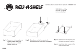
FIGURE 1A FIGURE 1B
FIGURE 2A
FACE FRAME CABINETS
Install bottom slide
1) Attach feet (#9) to bottom slide (C) using M4 screw (#8) as shown
in
eb ot deen lliw esolc-tfos eht ,toof raer eht hcatta oT .1
to remove the inner member(s) from the slide so you have a hollow
channel when attaching the feet.
Install top slide
3) The top slide (B) of the pantry needs to be mounted with the
draob recaps a hcatta dna tuc ot yrassecen eb ylekil lliw tI .emarf ecaf
as shown in
3.
Insert pantry frame
5) The bottom of the frame (A) sits on top of the bottom slide (C) as
shown in
.hcatta ot )3#( rehsaw dna )2#( wercs 6M esU .5
6) Slide the top portion of the frame up so that the top slide is
concealed but not touching the wood cabinet.
7) Two pins in top slide (B) insert into mating bushings in the top of
the frame (A) as shown in
6.
8) Tighten the two screws in 7.
C
B
B A
3
Top Spacer
Must be
with Face Frame
4) Using 4, mark 3 hole locations and drill ⁄ ” pilot holes.
Roughly align the front of the slide with the front of the face frame
morf draob recaps eht ot hcattA .tenibac eht ni edils eht retnec dna
step 3 using screws (#6).
2) Mark 12 hole locations and drill ⁄ eht ngila ylhguoR .seloh tolip ”
front of the slide with the front of the face frame and center the slide
eht ot hcattA .tenibac eht ni
using screws (#7). When using the
template to align the pilot hole, be sure to fold across the dotted line
on the front of the template to wrap over the face frame or front end
of the frameless cabinet. This will keep your slide from being installed
too far back into the cabinet. See
2.
A
C
A
C
(25)
(60)
(120)
(60)
(60)
(190)
(160)
(160)
(40)
UNIT : inch (mm)
#2
FIGURE 2B
CENTERLINE
cutting line for small cabinet
cutting line for small cabinet
FRONT SIDE
(DOOR)
IJģ
ĩijĶĪ
ijĮĴİĹģ
ĩķıĪ
IJĮĴİĴijģ
ĩijĹĪ
ĵĮĴİĵģ
ĩIJijıĪ
ijĮĴİĹģ
ĩķıĪ
ĸĮIJİijģ
ĩIJĺıĪ
ijĮĴİĹģ
ĩķıĪ
5300/5700 SERIES PULLOUT PANTRY BOTTOM SLIDE TEMPLATE
12400 Earl Jones Way
Louisville, KY 40299
rev-a-shelf.com
Customer Service: 800-626-1126
T-5700-BTM-0117
PASO 1
ÉTAPE 1
PASO 2
ÉTAPE 2


