Customer Service: 800-626-1126 | rev-a-shelf.com
4
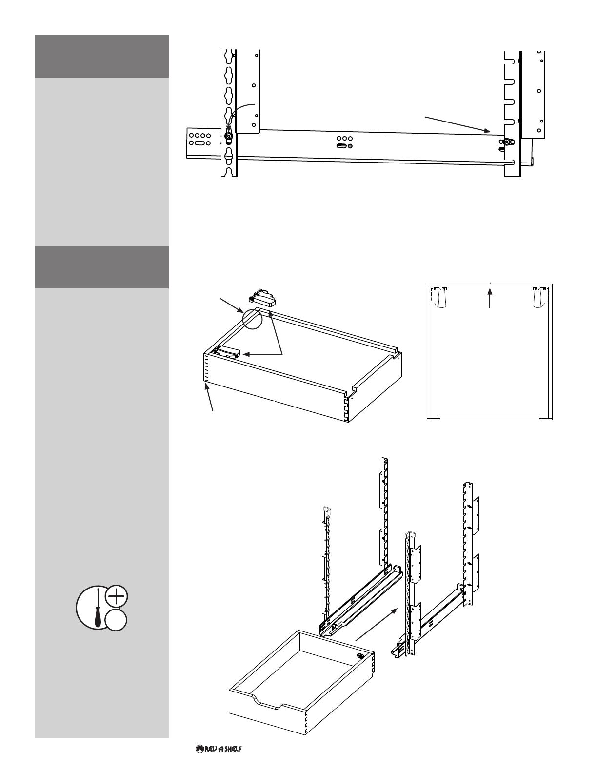
SLIDE INTO PLACE
ROTATE FRONT OF THE SLIDE
SO IT FITS INTO THE FRONT
PILASTER UPRIGHT
PUSH UNTIL YOU HEAR
A CLICKING SOUND
With the wood box upside
down, locate the front of the
box by identifying the pre-
drilled holes (See Fig 6.1).
Ensure the triggers are on the
correct side before attaching
the four #6x1/2” phillips pan
head deep thread wood
screws (See Fig 6.1).
Once the triggers are
attached, place the wood box
on top of the BLUM slides
and slowly push the wood
box back. When the slides
have fully engaged, you will
hear a “click” sound (See Fig
6.2). At this point, tighten the
screws connecting the Pilaster
Uprights to the L-Brackets
from Step 3 (See Fig 3.2).
NOTE: You will also use these
triggers to disengage the
wood boxes from the pilaster
system when necessary.
Locate the desired hole
locations for the Pilaster
Buttons to be inserted.
Insert the button attached to
the rear of the slide into the
back Pilaster Upright slot. Drop
the front slide button into the
center of the front upright slot
and press down to secure the
slide (See Fig 5).
#2
STEP 6
STEP 5
DRAWER BOX
PREPARATION
HANGING SLIDES ON
UPRIGHTS
FIGURE 5
FIGURE 6.1
FIGURE 6.2
BLUM TRIGGERS
PRE-DRILLED HOLE
LOCATIONS
FRONT OF BOX
FRONT OF BOX
DRAWER BOTTOM
AFTER TRIGGER
INSTALLATION


