
VictorTechnologies.com
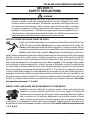
Aluminum Alloy
Firepower
MIG Spool Gun
Safety and
Operating
Instructions
Revision: AA Issue Date: August 2, 2014 Manual No.: 0-5362
www.firepower.com
MAX OUTPUT
160
AMPS
MIG
ALUMINUM
MATERIALS
FLEXIBLE G ASES
INERT
ARGON

WE APPRECIATE YOUR BUSINESS!
Congratulations on receiving your new Firepower product. We are proud to have
you as our customer and will strive to provide you with the best service and
support in the industry. This product is backed by our extensive warranty and
world-wide service network.
We know you take pride in your work and we feel privileged to provide you with
this high performance product that will help you get the job done.
YOU ARE IN GOOD COMPANY!
Firepower is a Global Brand of Arc Welding Products for Victor Technologies Inc.
We distinguish ourselves from our competition through market-leading innovation
and truly dependable products that will stand the test of time.
We strive to enhance your productivity, efficiency and welding performance
enabling you to excel in your craft. We design products with the welder in mind
delivering- advanced features, durability, ease of use and ergonomic comfort.
Above all, we are committed to a safer working environment within the welding
industry. Your satisfaction with this product and its safe operation is our ultimate
concern. Please take the time to read the entire manual, especially the Safety
Precautions.
If you have any questions or concerns regarding your new Firepower product,
please contact our friendly and knowledgeable Customer Service Team at:
1-800-462-2782 (USA) and 1-905-827-4515 (Canada),
or visit us on the web at www.Firepower.com

i
WARNINGS
Read and understand this entire Manual and your employer’s safety practices
before installing, operating, or servicing the equipment. While the information
contained in this Manual represents the Manufacturer’s judgment, the Manufacturer
assumes no liability for its use.
Firepower Spool Gun: 1444-0894
Set-up and Safe Operating Procedures
Instruction Guide Number 0-5362
Published by:
Victor Technologies, Inc.
16052 Swingley Ridge Road,
Suite 300 St. Louis, MO 63017
USA
www.firepower.com
U.S. Customer Care: (800) 426-1888
Canada Customer Care: 905-827-4515
International Customer Care: (940) 381-1212
Copyright © 2014 Victor Technologies International, Inc.
All rights reserved.
Reproduction of this work, in whole or in part, without written permission of the publisher is prohibited.
The publisher does not assume and hereby disclaims any liability to any party for any loss or damage
caused by any error or omission in this Manual, whether such error results from negligence, accident,
or any other cause.
Publication Date: Aug. 19, 2014
Record the following information for Warranty purposes:
Where Purchased:
Purchase Date:

ii
Table of Contents
SECTION 1: SAFETY PRECAUTIONS ..............................................................1-1
SECTION 2: MODEL SPECIFICATIONS ...........................................................2-5
SECTION 3: INSTALLATION AND OPERATION ...............................................3-7
3.01 Connecting the spool gun ........................................3-7
3.02 Adjusting wire feed pressure and speed ..................3-8
3.03 Installing the wire spool ..........................................3-8
SECTION 4: CARE AND MAINTENANCE .......................................................4-11
4.01 Changing the contact tip ........................................4-11
4.02 Changing the wire conduit .....................................4-12
4.03 Changing the drive rolls ........................................4-13
SECTION 5: TROUBLESHOOTING CHECK LIST .............................................5-15
SECTION 6: REPLACEMENT PARTS LIST .....................................................6-16
FIREPOWER - LIMITED WARRANTY TERMS ................................................6-18
WARRANTY SCHEDULE ...............................................................................6-19
GLOBAL CUSTOMER SERVICE CONTACT INFORMATION Rear Cover

SET-UP AND SAFE OPERATING PROCEDURES
1-1
89200016
Safety Precautions
SECTION 1:
SAFETY PRECAUTIONS
WARNING
SERIOUS INJURY OR DEATH may result if welding and cutting equipment is not
properly installed, used, and maintained. Misuse of this equipment and other
unsafe practices can be hazardous. The operator, supervisor, and helper must read
and understand the following safety warnings and instructions before installing
or using any welding or cutting equipment, and be aware of the dangers of the
welding or cutting process. Training and proper supervision are important for a
safe work place. Keep these instructions for future use. Additional recommended
safety and operating information is referenced in each section.
ELECTRIC SHOCK CAN CAUSE INJURY OR DEATH
Install and maintain equipment in accordance with the National Electrical Code
(NFPA 70) and local codes. Do not service or repair equipment with power ON.
Do not operate equipment with protective insulators or covers removed. Service
or repair to equipment must be done by qualified and/or trained personnel only.
Do not contact electrically live parts. Always wear dry welding gloves that are in
good condition. Aluminized, protective clothing can become part of the electrical path. Keep oxygen
cylinders, chains, wires, ropes, cranes, and hoists away from any part of the electrical path. All
ground connections must be checked periodically to determine if they are mechanically strong,
and electrically adequate for the required current. When engaged in AC welding/cutting under
wet conditions or where perspiration is a factor, the use of automatic controls for reducing the
no load voltage is recommended to reduce shock hazards. Accidental contact must be prevented
when using open circuit voltage exceeding 80 volts AC, or 100 volts DC by adequate insulation
or other means. When welding is to be suspended for any length of time, such as during lunch or
overnight, all electrode holders and electrodes should be removed from the electrode holder and
the power supply should be turned OFF to prevent accidental contact. Keep MIG-Guns, electrode
holders, Tig torches, Plasma torches, and electrodes away from moisture and water. See safety
and operating references 1, 2, and 8.
SMOKE, FUMES, AND GASES CAN BE DANGEROUS TO YOUR HEALTH
Ventilation must be adequate to remove smoke, fumes, and gases during
operation to protect operators and others in the area. Vapors of chlorinated
solvents can form the toxic gas “Phosgene” when exposed to ultraviolet radiation
from an electric arc. All solvents, degreasers, and potential sources of these
vapors must be removed from the operating area. Use air-supplied respirators
if ventilation is not adequate to remove all fumes and gases. Oxygen supports, and vigorously
accelerates fire and should never be used for ventilation. See safety and operating references
1, 2, 3, and 4.

1-2
SET-UP AND SAFE OPERATING PROCEDURES
89200016Safety Precautions
ARC RAYS, HOT SLAG, AND SPARKS CAN INJURE EYES AND BURN SKIN
Welding and cutting processes produce extreme localized heat and strong
ultraviolet rays. Never attempt to weld/cut without a federally compliant welding
helmet with the proper lens. A number 12 to 14 shade filter lens provides the
best protection against arc radiation. When in a confined area, prevent the
reflected arc rays from entering around the helmet. Approved shielding curtains
and appropriate goggles should be used to provide protection to others in the surrounding area.
Skin should be protected from arc rays, heat, and molten metal. Always wear protective gloves
and clothing. All pockets should be closed and cuffs sewn shut. Leather aprons, sleeves, leggings,
etc. should be worn for out-of-position welding and cutting, or for heavy operations using large
electrodes. Hightop work shoes provide adequate protection from foot burns. For added protection,
use leather spats. Flammable hair preparations should not be used when welding/cutting. Wear
ear plugs to protect ears from sparks. Where work permits, the operator should be enclosed in
an individual booth painted with a low reflective material such as zinc oxide. See safety and
operating references 1, 2, and 3.
WELDING SPARKS CAN CAUSE FIRES AND EXPLOSIONS
Combustibles reached by the arc, flame, flying sparks, hot slag, and heated
materials can cause fire and explosions. Remove combustibles from the work
area and/or provide a fire watch. Avoid oily or greasy clothing as a spark may
ignite them. Have a fire extinguisher nearby, and know how to use it. If welding/
cutting is to be done on a metal wall, partition, ceiling, or roof, precautions must
be taken to prevent ignition of nearby combustibles on the other side. Do not
weld/cut containers that have held combustibles. All hollow spaces, cavities, and containers
should be vented prior to welding/cutting to permit the escape of air or gases. Purging with inert
gas is recommended. Never use oxygen in a welding torch. Use only inert gases or inert gas
mixes as required by the process. Use of combustible compressed gases can cause explosions
resulting in personal injury or death. Arcing against any compressed gas cylinder can cause
cylinder damage or explosion. See safety and operating references 1, 2, 5, 7, and 8.
NOISE CAN DAMAGE HEARING
Noise from the air carbon-arc process can damage your hearing. Wear protective
hearing devices to ensure protection when noise levels exceed OHSA standards.
Adequate hearing protection devices must be worn by operators and surrounding
personnel to ensure personal protection against noise. See safety and operating
references 1, 2, and 6.
WARNING
WARNING: This product contains chemicals, including lead, known to the State of
California to cause birth defects and other reproductive harm. Wash hands after
handling.

SET-UP AND SAFE OPERATING PROCEDURES
1-3
89200016
SAFETY AND OPERATING REFERENCES
1. Code of Federal Regulations (OSHA) Section 29, Part 1910.95, 132, 133, 134, 139, 251,
252, 253, 254 and 1000. U.S. Government Printing Office, Washington, DC 20402.
2. ANSI Z49.1 “Safety in Welding and Cutting”.
3. ANSI Z87.1 “Practice for Occupational and Educational Eye and Face Protection”.
4. ANSI Z88.2. “Standard Practice for Respiratory Protection”. American National Standards
Institute, 1430 Broadway, New York, NY 10018.
5. AWS F4.1. “Recommended Safe Practices for Welding and Cutting Containers”.
6. AWS C5.3. “Recommended Practices for Air Carbon-Arc Gouging and Cutting”. The
American Welding Society, 550 NW Lejeune Rd., P.O. Box 351040, Miami, FL 33135.
7. NFPA 51B. “Fire Prevention in Cutting and Welding Processes”.
8. NFPA-7. “National Electrical Code”. National Fire Protection Association, Battery Park,
Quincy, MA 02269.
9. CSA W117.2. “Safety in Welding, Cutting and Allied Processes”. Canadian Standards
Association, 178 Rexdale Blvd., Rexdale, Ontario, Canada M9W 1R3.
Safety Precautions

1-4
SET-UP AND SAFE OPERATING PROCEDURES
89200016
This Page Intentionally Blank

SET-UP AND SAFE OPERATING PROCEDURES
2-5
89200016
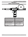
SECTION 2:
MODEL SPECIFICATIONS
Description Rating
Rated Welding Current C0
2
160A
Duty Cycle 20%
Wire Diameter (Normal) 0.023-0.035 (Normal)
Wire Diameter (Stainless Steel) 0.023-0.030 (Stainless Steel)
Maximum Wire Feed Speed 630 in./min. (16 m/min.)
Maximum Wire Spool Size
Diameter: 4” (100 mm)
Width: 1.75” (45 mm)
Motor Voltage 24V DC
Model Specifications

2-6
SET-UP AND SAFE OPERATING PROCEDURES
89200016
This Page Intentionally Blank

SET-UP AND SAFE OPERATING PROCEDURES
3-7
89200016
SECTION 3:
INSTALLATION AND OPERATION
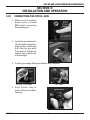
3.01 CONNECTING THE SPOOL GUN
1. Make sure the welding
power source is turned
OFF before connecting
the welding gun.
2. Insert the gun connection
into the feeder receptacle,
aligning the conduit plug
first, then the gas plug.
Push until all fittings are
seated then tighten the
nut hand tight.
3. Connect gas supply fitting and tighten with a wrench.
3A. Inlet - USA model 3B. Outlet
4. Align Control Plug to
panel fitting and tighten
securely.
Installation and Operation

3-8
SET-UP AND SAFE OPERATING PROCEDURES
89200016
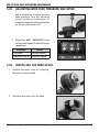
3.02 ADJUSTING WIRE FEED PRESSURE AND SPEED
1. Use a screwdriver to adjust the wire
feed pressure. Turn the adjusting
screw clockwise to decrease, or
counterclockwise to increase pressure
on the wire feed drive rolls.
2. Adjust the “AMP” (WIRESPEED) knob
on the power supply to adjust the wire
speed feed.
Direction Result
Clockwise Increase Speed
Counterclockwise Decrease Speed
3.03 INSTALLING THE WIRE SPOOL
1. Remove the spool cover by loosening
the cover screw by hand.
2. Slide the wire spool onto the shaft.
Installation and Operation

SET-UP AND SAFE OPERATING PROCEDURES
3-9
89200016
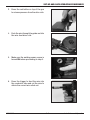
3. Press the red button on top of the gun
to release pressure from the drive rolls.
4. Push the wire through the guide and into
the wire feed drive rolls.
5. Make sure the welding power source is
turned ON before proceeding to step 6.
6. Press the trigger to feed the wire into
the conductor tube and cut the wire to
obtain the correct wire stick-out.
Installation and Operation

3-10
SET-UP AND SAFE OPERATING PROCEDURES
89200016
7. Adjust the friction nut on the spool shaft
to apply the correct wire tension. Spool
should stop when trigger is released.
8. Replace the wire spool cover and hand
tighten the cover screw.
Installation and Operation

SET-UP AND SAFE OPERATING PROCEDURES
4-11
89200016
SECTION 4:
CARE AND MAINTENANCE
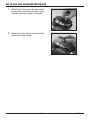
4.01 CHANGING THE CONTACT TIP
NOTE
Replace contact tip if hole is enlarged or deformed.
1. Select the correct contact tip according
to the wire used.
2. Remove the nozzle from the gun to
reveal the contact tip.
3. Remove the contact tip using pliers if
needed. Replace contact tip and tighten
securely.
NOTE
Periodically clean spatter from the inside of the nozzle and holes of the gas diffuser.
Use anti-spatter spray for best results.
Care and Maintenance

4-12
SET-UP AND SAFE OPERATING PROCEDURES
89200016
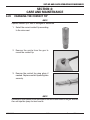
4.02 CHANGING THE WIRE CONDUIT
NOTE
Replace liner if hole is obstructed. Make sure the end of the liner is smooth.
1. Turn the power source OFF and
disconnect the gun.
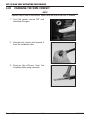
2. Unscrew the nozzle and remove it
from the conductor tube.
3. Remove the diffuser from the
conductor tube using a wrench.
Care and Maintenance

SET-UP AND SAFE OPERATING PROCEDURES
4-13
89200016
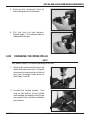
4. Remove the conductor tube by
unscrewing the nut at the base.
5. Pull the liner out and replace.
Repeat steps 1-4 in reverse order to
reassemble the gun.
4.03 CHANGING THE DRIVE ROLLS
NOTE
Turn power supply OFF before replacing drive rolls.
1. Remove the screws which secure the
upper and lower drive rolls. It may be
necessary to remove drive roll side of
gun case to change lower drive roll
(see steps 2 and 3).
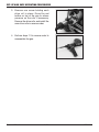
2. Loosen four handle screws. Turn
ring on the bottom of the handle
(surrounding the speed control knob)
one-quarter turn counter-clockwise,
and remove.
Care and Maintenance

4-14
SET-UP AND SAFE OPERATING PROCEDURES
89200016
3. Remove one screw holding each
drive roll in place. Press the red
button on top of the gun to relieve
pressure on the rolls if necessary.
Remove the drive rolls, and install the
new drive rolls in reverse order.
4. Perform steps 1-3 in reverse order to
reassemble the gun.
Care and Maintenance

SET-UP AND SAFE OPERATING PROCEDURES
5-15
89200016
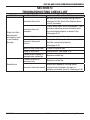
SECTION 5:
TROUBLESHOOTING CHECK LIST
Problem Possible Cause Corrective Action
Drive rolls turn
but wire will
not feed or wire
is not feeding
through
Incorrect drive rolls
Be sure the wire diameter being used is
stamped on the drive rolls. Replace drive
rolls if necessary.
Incorrect drive roll
pressure
Check and correct drive roll pressure. Turn
pressure adjusting screw clockwise until
the wire feeds properly or doesn’t slip.
(See page 3-6)
Worn or dirty drive rolls Clean or replace drive rolls.
Incorrect wire spool
friction
Adjust the friction nut on the spool shaft to
find the correct wire tension.
(See page 4-8)
Worn or dirty outlet liner Clean or replace liner.
Rusty or dirty wire Replace wire. (See page 3-6)
Partially arced, melted, or
improper size contact tip
Replace contact tip.
Variable arc
Contact tip worn or
incorrect size
Replace contact tip.
Incorrect wire feed speed
Adjust wire speed by turning speed
control knob clockwise (to max) or
counter-clockwise (to min). (See page 3-6)
Troubleshooting Check List

6-16
SET-UP AND SAFE OPERATING PROCEDURES
89200016
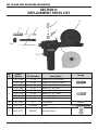
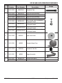
SECTION 6:
REPLACEMENT PARTS LIST
1
2
3
5
6
10
4
8
9
7
11
Ref
#
Stock
Number Part Number Description
Image
1
1110-1100 11-23 Contact Tip .023 (0.6 mm)
1110-1101 11-30 Contact Tip .030 (10.8 mm)
1110-1102 11-35 Contact Tip .035 (10.9 mm)
2
1210-1300 21T-37 Nozzle 3/8" (9.5 mm)
1210-1100 21-37 Nozzle 3/8" (9.5 mm)
1210-1110 21-50 Nozzle 1/2" (12.7 mm)
1210-1112 21-50F Nozzle 1/2" (12.7 mm)
1210-1120 21-62 Nozzle 5/8" (15.9 mm)
3 1510-1101 51 Gas Diffuser
4 2031-2107 SPG66065 Conduit
5 2031-2227 WSPDRC Drive Roll Cover
Replacement Parts List
Page is loading ...
Page is loading ...
Page is loading ...
Page is loading ...
-
 1
1
-
 2
2
-
 3
3
-
 4
4
-
 5
5
-
 6
6
-
 7
7
-
 8
8
-
 9
9
-
 10
10
-
 11
11
-
 12
12
-
 13
13
-
 14
14
-
 15
15
-
 16
16
-
 17
17
-
 18
18
-
 19
19
-
 20
20
-
 21
21
-
 22
22
-
 23
23
-
 24
24


Firepower Firepower Mig Spool Gun User manual
- Type
- User manual
- This manual is also suitable for
Ask a question and I''ll find the answer in the document
Finding information in a document is now easier with AI
Related papers
-
ESAB Spool Gun User manual
-
ESAB FP-160 User manual
-
-
-
-
-
ESAB FP-235 User manual
-
-
-
Other documents
-
-
-
-
-
-
-
-
-
-