Page is loading ...

1
2
3
4
FOLD LINE ‘A’
FOLD LINE ‘B’
Nut with Nylon Insert
(This sets Brake Tension)
12” (305mm)
diameter spool
Wire
Direction
A) Fit the MIG Torch to the power source by pushing the MIG torch connector into the
MIG torch adaptor and screwing the plastic torch nut clockwise to secure the MIG torch to
the MIG torch adaptor.
MIG Gun Adaptor
(outside surface)
MIG Gun
Connector
Wire
Torch Nut
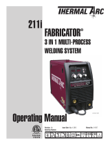
1. INSTALL Wire Spool (12” Dia.)
Wire Drive
Tension Screw
Arm
Inlet Guide
Wire Drive
Tension Screw
Pressure Roller Arm
Feed Wire
TILT
A) Drive Roll installed on machine is .030". If running other wire sizes and wire types
please see Operators Manual.
B) Install Spool
• Open side panel of 220i and mount the 12” diameter Wire Spool on Spool Hub.
Ensure Wire Spool seats onto Spool Hub Pin. (See Operator’s Manual for
alternate 8” and 4” diameter spool set up.)
• Hand feed the wire from the spool into the Inlet Guide. (Wire is under tension.)
• Tilt the Wire Drive Tension Screw Arm toward the rear of the machine and
feed the wire through the Outlet Guide about 3”.
• Return the Wire Drive Tension Screw Arm to the upright position locking the
Pressure Roller Arm underneath it. Ensure wire is seating in drive roll groove.
• Turn Wire Drive Tension Screw clockwise until drive roll grips wire.
Drive Roll and Drive Roll Knob
Drive Roll
Feed Wire
System
{
Outlet Guide
TRIGGER
WIRE
MIG GUN
TRIM
Gas Outlet
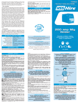
A) Attach the regulator to the cylinder valve and tighten securely with a wrench.
B) Purge the regulator by SLIGHTLY opening the cylinder valve for 3-to-5 seconds
and then close.
C) Connect the 220i gas hose to the gas outlet on the regulator. Wrench tight 1/4 turn.
D) Slowly and carefully open the cylinder valve until the maximum pressure
shows on the High-Pressure gauge.
E) Adjust regulator knob on the Low-Pressure gauge so the needle is
in the MIG, (Green Section).
2. SETUP Gas Regulator
Cylinder Valve
Regulator
High-PressureLow-Pressure
Tighten with
wrench
Regulator
Adjusting
Knob
Clamp to work piece
before starting to weld.
Work Clamp
Work Clamp
Connector
G
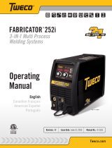
MIG Gun Connector
B) Plug the 220i into a 115, 208, or 230V outlet.
3. SETUP MIG Gun
C) Turn the Power Switch ON. (Located on the rear of the machine.)
D) Select MIG PROCESS.
E) Select 2T for TRIGGER.
F) Turn WIRESPEED Dial to Five. (Halfway between 4 and 6 marks)
G) Switch the LOCAL/REMOTE switch inside the wire feed
compartment to LOCAL.
Then switch the MIG GUN/SPOOL GUN switch to MIG GUN.
H) Lay the MIG Gun out so the cable is straight with NO twists or kinks.
• Unscrew nozzle and pop out the tip from MIG gun.
• Point the MIG Gun AWAY from your body. Press and hold the
MIG Gun trigger. The wire will advance through the cable and
out the MIG Gun conductor tube. Release the MIG Gun trigger.
• Reinstall MIG Gun tip and nozzle.
• Trim the wire at the MIG Gun nozzle to desired stick out.
• Close the 220i side panel.
A) Select MIG PROCESS.
B) Determine what material type and thickness you plan to weld (24 ga. through 1/16” thickness).
C) Determine what wire type and diameter you plan to use (.030”recommended).
D) Determine what shielding gas you plan to use (75% Ar/25% CO
2
recommended).
E) Quick Start Parameters:
for 16 gauge (1.6 mm) using 115V
1) Wirespeed Display: 219
2) Voltage Display: 16.0 (16.0V)
3) Inductance Setting: 8 (+HARD)
Otherwise, refer to your ‘Recommended Settings Chart’ below for
Wirespeed, Voltage, and Inductance Settings.
F) Attach Work Clamp connector to 220i.
Check for Positive polarity setting — see picture.
G) Attach Work Clamp to work piece.
4. SET Welding Parameters
OPTIONAL: Installing or Replacing Nozzle or Tip
1.) Unplug the 220i.
2.) Unscrew worn nozzle and pop out the tip.
3.) Slide new contact tip into the conductor tube end.
(Tip does not screw in.)
4.) Replace the nozzle. Hand tighten (Nozzle secures tip).
NOTE: For proper operation the nozzle MUST be tight.
5.) Trim wire to desired stick out.
NOZZLE
TIP
TRIGGER
MIG GUN
*Recommended
115V Quick Start
Parameters
You may begin welding.
220i Shut Down
A) Turn the Power Switch OFF.
(Located on the rear of the machine.)
B) Turn cylinder valve OFF and
bleed downstream gas line by loosening
hose at back of 220i.
When nished welding, remember to
properly shut down the 220i.
Spool Hub
Pin hole
Side Panel
Recommended Settings Chart
(For your reference this chart is also on the inside side panel.)
.030
0.8
.030” (0.8 mm) Stamp
Tack Weld
MIG Gun
MIG WELDING Step outline:
1) INSTALL Wire spool
2) SETUP Gas Regulator
3) SETUP MIG Gun
4) SET Welding Parameters
Quick Start Guide
MIG WELDING (0.030” Solid Wire)
MST 220i
Publication Date: March 12, 2014Revision: AAQuick Start Guide Number: 0-5344
3-IN-1 Multi Process Welding Systems

F
i
r
e
p
o
w
e
r
Electrode
Holder
Work Clamp
(ground)
MIG Torch
polarity lead
(leave loose)
+
−
Work Piece
A) Open side panel of 220i and switch the LOCAL/REMOTE switch inside the
wire feed compartment to LOCAL to use the Power Sources Amperage control.
B) Close the 220i side panel.
C) Disconnect the MIG Torch polarity lead and leave loose.
D) Connect the Electrode Holder lead to the positive welding terminal (+).
E) Connect the work clamp (ground) lead to the negative welding terminal (-).
F) Connect the work clamp to the work piece.
G) Plug the 220i into a 115, 208, or 230V outlet and turn the 220i
Power Switch ON.
H) Quick Start Parameters: (for 3/32” Electrode)
1) Select STICK mode with the Process Selection control.
2) Amperage Display (Wirespeed) : between 60-85A
3) Arc Force : 50% (#5)
I) Install Electrode into Electrode Holder and begin welding.
(Electrode is electrically live as soon as it is in the Electrode Holder.)
MS = Mild Steel SS= Stainless Steel
Firepower 220A MIG Gun
MST 220i
3-IN-1 Multi Process Welding Systems
Optional Parts: Tools required:
Parts Included:
(Not Shown to Scale)
© 2014 Victor Technologies International, Inc. www.victortechnologies.com Printed in China
U.S. Customer Care: 800-426-1888 / fax 800-535-0557 • Canada Customer Care: 905-827-4515 / fax 800-588-1714
International Customer Care: 940-381-1212 / fax 940-483-8178 • CIGWELD Customer Care: 1 300-654-674 / fax 61-3-9474-7391
INNOVATION TO SHAPE THE WORLD
™
TECHNOLOGIES
™
Copyright © 2014 Victor Technologies, Inc. All rights reserved.
Reproduction of this work, in whole or in part, without written permission of
the publisher is prohibited.
The publisher does not assume and hereby disclaims any liability to any
party for any loss or damage caused by any error or omission in this Quick Start Guide,
whether such error results from negligence, accident, or any other cause.
Publication Date: 03/14/2014
200A Ground Clamp
200A Electrode Holder
Power Cord Adapter
Velocity Contact Tips
Operators Manual & CD
Quick Start Guide
Argon
Regulator/Gauge
Tack Weld
TIG Torch
Tack Weld
Work Clamp
MIG Torch
polarity lead
(leave loose)
TIG Torch trigger
switch connector
TIG Torch
gas hose
TIG Torch
TIG Torch
DINSE connector
220i Shut Down
A) Turn cylinder valve OFF and bleed downstream gas line.
B) Turn the Power Switch OFF. (Located on the rear of the machine.)
Electrode
220i Shut Down
A) Turn the Power Switch OFF.
(Located on the rear of the machine.)
Tack Weld
Electrode
Holder
Tack Weld
Read and understand this entire guide, the Operating Manual and your
employer’s safety practices before installing, operating, or servicing the equipment.
While the information contained in this guide represents the Manufacturer’s
best judgment, the Manufacturer assumes no liability for its use.
Refer to the 220i Operation Manual for detailed safety and operation instructions.
WARNINGS and CAUTIONS
• ELECTRIC SHOCK can kill. Touching live electrical parts can cause fatal shocks or severe burns.
• Incorrectly installed or improperly grounded equipment is a hazard.
• The MIG welding wire and work circuit is electrically live whenever the output is ON.
• The MIG wire, wire reel, drive roll housing, and all metal parts touching the welding wire are
electrically live whenever the output is ON.
• STICK Electrode is electrically live as soon as it is in the Electrode Holder.
• Never stand in front of or behind a regulator when opening the cylinder valve!
• DO NOT attach or use the regulator if oil, grease, ammable substances, or damage is present!
Stand to the side of the cylinder opposite the regulator when opening the cylinder valve.
Keep the cylinder valve between you and the regulator.
• NEVER use a compressed gas cylinder without a pressure reducing regulator attached to the cylinder valve.
• Always use a regulator designed for the type gas used.
• DO NOT point MIG Gun at your face.
• Maintain an adequate distance of the wire from metal objects to avoid burnbacks to conduit or conductor tube.
• Always wear a welding helmet tted with a proper shade of lter (see Safety Standards in the Operation manual) to
protect your face and eyes when welding or watching, and safety equipment when welding.
STICK WELDING Step outline:
1) INSTALL Electrode Holder
2) SET Welding Parameters
TIG WELDING Step outline:
1) INSTALL TIG Torch
2) SETUP Gas Regulator
3) SET Welding Parameters
17V TIG Torch
(with an 8 pin plug)
Foot Control
(with an 8 pin plug)
Work Piece
Drive Roll
Gas Hose
(not shown)
Stick Electrodes (Not provided)
NOTES
• If the wire does NOT advance through the MIG Gun, release MIG Gun trigger, lay the gun down,
unplug the machine and adjust the Wire Drive Tension Screw inside the 220i side panel.
REQUIRED
ITEMS
Quick Start Guide
TIG WELDING (LIFT TIG)
TIG Torch and parts are NOT supplied with the 220i. Before beginning TIG Welding
you must have a 17V TIG Torch with an 8 pin plug and Tungsten Electrode(s).
OPTIONAL: a Foot Control with an 8 pin plug and/or Filler Metal (Wire).
17V TIG Torch
(with an 8 pin plug)
ACCESSORY
Foot Control
(with an 8 pin plug)
Tungsten Electrode(s)
OPTIONAL
Filler Metal (Wire)
SAFETY STATEMENTS
REQUIRED
ITEMS
200A Electrode Holder
A) Open side panel of 220i and switch the LOCAL/REMOTE switch inside the
wire feed compartment to LOCAL to use the Power Sources Amperage control.
or
Switch the LOCAL/REMOTE switch inside the wire feed compartment to
REMOTE for remote amperage using a Foot Control.
B) Close the 220i side panel.
C) Disconnect the MIG Torch polarity lead and leave loose.
D) Connect the TIG Torch DINSE connector to the negative welding terminal (-).
• Connect the work lead to the positive welding terminal (+).
• Connect the TIG Torch trigger switch to the 8 pin socket.
(The TIG Torch will require a trigger switch to weld in LIFT TIG Mode.)
E) Attach the regulator to the cylinder valve and tighten securely with a wrench.
• Connect the 220i gas hose to the gas outlet on the regulator.
• Purge the regulator by SLIGHTLY opening the cylinder valve
for 3-to-5 seconds and then close.
• Connect the shielding gas hose from the TIG Torch gas hose to the regulator.
Your TIG Torch must have a gas valve control or be connected
to a foot control device.
F) Connect the work clamp (ground) to the work piece.
G) Prepare the electrode tip and then insert the electrode in the TIG Torch.
H) Plug the 220i into a 115, 208, or 230V outlet.
I) Quick Start Parameters: (for 3/32” Electrode)
1) Select LIFT TIG mode with the Process Selection control.
2) Amperage Display (Wirespeed) : between 115-1705A
J) Turn ON shielding gas at the cylinder.
K) Depress foot control or press trigger on TIG Torch.
L) Begin Welding.
Recommended Settings Chart (For your reference this chart is also on the inside side panel.)
Recommended Settings Chart
(For your reference this chart is also on the inside side panel.)
Select STICK
Set ARC FORCESet AMPERAGE
Select LIFT TIG
Set AMPERAGE
+
−
HIGH P
URITY AND
I
N
S
TRUMENTATION
Regulator
Quick Start Guide
STICK WELDING
(Electrode)
Firepower MST 220i
3-IN-1 Multi Process
Welding Systems
Operating
Manual
www.Firepower.com
English
Canadien Français
Americas Español
Revision:
AA
Issue Date:
April 18, 2014
Manual No.:
0-5343
1
FOLDLINE
‘
A
’
FOLDLINE
‘
B
’
Nut with Nylon Insert
(This sets Brake Tension)
12” (305mm)
diameter spool
Wire
Direction
1. INSTALL Wire Spool (12” Dia.)
Wire Drive
Tension Screw
Arm
Inlet Guide
Wire Drive
Tension Screw
Pressure Roller Arm
Feed Wire
TILT
A)
Drive Roll installed on machine is .030". If running other wire sizes and wire types
please see Operators Manual.
B)
Install Spool
• Open side panel of 220i and mount the 12” diameter Wire Spool on Spool Hub.
Ensure Wire Spool seats onto Spool Hub Pin. (See Operator’s Manual for
alternate 8” and 4” diameter spool set up.)
• Hand feed the wire from the spool into the Inlet Guide. (Wire is under tension.)
• Tilt the Wire Drive Tension Screw Arm toward the rear of the machine and
feed the wire through the Outlet Guide about 3”.
• Return the Wire Drive Tension Screw Arm to the upright position locking the
Pressure Roller Arm underneath it. Ensure wire is seating in drive roll groove.
• Turn Wire Drive Tension Screw clockwise until drive roll grips wire.
Drive Roll and Drive Roll Knob
Drive Roll
Feed Wire
System
{
Outlet Guide
Spool Hub
Pin hole
Side Panel
.030
0.8
.030” (0.8 mm) Stamp
MIG WELDING Step outline:
1) INSTALL Wire spool
2) SETUP Gas Regulator
3) SETUP MIG Gun
4) SET Welding Parameters
Quick Start Guide
MIG WELDING
(0.030” Solid Wire)
MST 220i
Publication Date: March 12, 2014
Revision: AA
Quick Start Guide Number: 0-5344
3-IN-1 Multi Process Welding Systems
MST 220i Power Source
.035
0.9
/