
Documentation
eXtended Transport System Start-Up
1.2
2016-02-18
Version:
Date:


Table of content
Table of content
1 Foreword ....................................................................................................................................................5
1.1 Notes on the documentation............................................................................................................. 5
1.2 Documentation issue status.............................................................................................................. 6
1.3 Intended use ..................................................................................................................................... 6
2 Guidelines and Standards ........................................................................................................................7
3 Safety..........................................................................................................................................................8
3.1 General safety instructions ............................................................................................................... 8
3.1.1 Personnel qualification..........................................................................................................8
3.1.2 Description of safety symbols ...............................................................................................8
3.2 Special safety instructions ............................................................................................................... 9
3.3 Using in Ex environments ............................................................................................................... 10
4 Handling ...................................................................................................................................................11
4.1 Transport ........................................................................................................................................ 11
4.2 Packaging ....................................................................................................................................... 11
4.3 Storage ........................................................................................................................................... 12
4.4 Maintenance / Cleaning .................................................................................................................. 12
4.4.1 Replacement of the guide rollers ........................................................................................13
4.5 Disposal .......................................................................................................................................... 14
5 Product identification..............................................................................................................................15
5.1 Scope of supply .............................................................................................................................. 15
5.2 Type label ....................................................................................................................................... 15
5.3 Type key ......................................................................................................................................... 16
6 Technical description..............................................................................................................................18
6.1 General technical data.................................................................................................................... 18
6.1.1 Dimensions .........................................................................................................................19
6.1.2 Connection diagram XTS-Infeed.........................................................................................20
6.1.3 Connection overview...........................................................................................................21
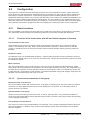
6.2 Configuration ................................................................................................................................. 22
6.2.1 Basic functions....................................................................................................................22
6.2.2 Use of the basic functions...................................................................................................23
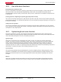
6.2.3 System length and curve function.......................................................................................23
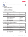
6.3 Overview ........................................................................................................................................ 24
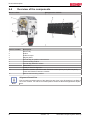
6.4 Overview of the components .......................................................................................................... 26
7 Installation................................................................................................................................................28
7.1 Mechanical installation.................................................................................................................... 28
7.2 Overview of the tightening torques ................................................................................................. 29
7.3 Mounting the movers on the guide rail............................................................................................ 31
7.4 The positioning system ................................................................................................................... 33
7.4.1 Zero point of the encoder system .......................................................................................33
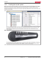
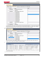
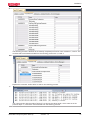
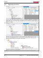
7.4.2 Teaching the encoder system.............................................................................................34
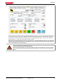
7.4.3 Application simulation .........................................................................................................40
7.5 Collision avoidance......................................................................................................................... 41
7.5.1 Operating principle of collision avoidance...........................................................................41
8 Technical data..........................................................................................................................................45
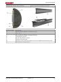
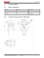
8.1 AT9011-0050-0550......................................................................................................................... 45
8.2 Technical drawing AT9011-0050-0550........................................................................................... 45
eXtended Transport System Start-Up 3
Version: 1.2


Foreword
1 Foreword
1.1 Notes on the documentation
This description is only intended for the use of trained specialists in control and automation engineering who
are familiar with the applicable national standards.
It is essential that the following notes and explanations are followed when installing and commissioning
these components.
The responsible staff must ensure that the application or use of the products described satisfy all the
requirements for safety, including all the relevant laws, regulations, guidelines and standards.
Disclaimer
The documentation has been prepared with care. The products described are, however, constantly under
development.
For that reason the documentation is not in every case checked for consistency with performance data,
standards or other characteristics.
In the event that it contains technical or editorial errors, we retain the right to make alterations at any time
and without warning.
No claims for the modification of products that have already been supplied may be made on the basis of the
data, diagrams and descriptions in this documentation.
Trademarks
Beckhoff
®
, TwinCAT
®
, EtherCAT
®
, Safety over EtherCAT
®
, TwinSAFE
®
, XFC
®
and XTS
®
are registered
trademarks of and licensed by Beckhoff Automation GmbH.
Other designations used in this publication may be trademarks whose use by third parties for their own
purposes could violate the rights of the owners.
Patent Pending
The EtherCAT Technology is covered, including but not limited to the following patent applications and
patents:
EP1590927, EP1789857, DE102004044764, DE102007017835
with corresponding applications or registrations in various other countries.
The TwinCAT Technology is covered, including but not limited to the following patent applications and
patents:
EP0851348, US6167425 with corresponding applications or registrations in various other countries.
EtherCAT
®
is registered trademark and patented technology, licensed by Beckhoff Automation GmbH,
Germany
Copyright
© Beckhoff Automation GmbH & Co. KG, Germany.
The reproduction, distribution and utilization of this document as well as the communication of its contents to
others without express authorization are prohibited.
Offenders will be held liable for the payment of damages. All rights reserved in the event of the grant of a
patent, utility model or design.
eXtended Transport System Start-Up 5
Version: 1.2

Foreword
1.2 Documentation issue status
Issue Comment
1.2 Chapter update:
4.2; 4.5; 6.1.1; 6.1.2; 6.2.3; 6.4; 7.2; 7.5.1; 7.5.2
New and deleted chapter:
New: 4.4.1; 6.1.3
Deleted: 7.3
1.1 Chapter update:
3.2; 6.1; 6.1.1, 7.3
New chapter:
Technical data
1.0 First edition
1.3 Intended use
The linear eXtended Transport System (XTS) is designed for machines and equipment with the highest
demands on dynamics and positioning accuracy. All components of the eXtended Transport System (XTS)
are exclusively intended to be programmed and commissioned using the TwinCAT automation software
from Beckhoff Automation GmbH & Co. KG.
WARNING
Caution - Risk of injury!
Electronic equipment is not fail-safe. In case of failure of the drive system, the machine
manufacturer is responsible for ensuring that the connected components of the eXtended
Transport System (XTS) and the machine are brought into a safe state.
WARNING
Commissioning of the eXtended Transport System (XTS)
The eXtended Transport System (XTS) must be commissioned based on the requirements
of the currently valid EU Machinery Directive. Furthermore, the client must ensure that all
components installed in the system have a valid serial number.
All components of the eXtended Transport System (XTS) are installed exclusively in electrical systems or
machines. They may only be commissioned in connection with components of the eXtended Transport
System (XTS) and the previously designed plant. Furthermore, it is essential to take into account all
environmental conditions defined in this document before the eXtended Transport System (XTS) is
commissioned.
eXtended Transport System Start-Up6
Version: 1.2

Guidelines and Standards
2 Guidelines and Standards
CAUTION
Danger for persons, the environment or equipment
The components of the XTS are not products within the meaning of the EC Machinery Di-
rective. Operation of the XTS components in machines or systems is only permitted once
the machine or system manufacturers has provided evidence of CE conformity of the com-
plete machine or system.
eXtended Transport System Start-Up 7
Version: 1.2

Safety
3 Safety
3.1 General safety instructions
3.1.1 Personnel qualification
This description is only intended for trained specialists in control, automation and drive engineering who are
familiar with the applicable national standards.
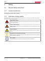
3.1.2 Description of safety symbols
The following safety symbols and associated safety instructions are used in this document. These safety
instructions must be read and followed.
DANGER
Serious risk of injury!
Failure to follow the safety instructions associated with this symbol directly endangers the
life and health of persons.
WARNING
Caution - Risk of injury!
Failure to follow the safety instructions associated with this symbol endangers the life and
health of persons.
CAUTION
Personal injuries!
Failure to follow the safety instructions associated with this symbol can lead to injuries to
persons.
Attention
Damage to the environment or devices!
Failure to follow the safety instructions associated with this symbol can lead to damage to
the environment or equipment.
Note
Tip or pointer
This symbol indicates information that contributes to better understanding.
eXtended Transport System Start-Up8
Version: 1.2

Safety
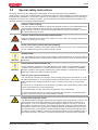
3.2 Special safety instructions
The safety instructions are designed to avert danger and must be followed during installation,
commissioning, production, troubleshooting, maintenance and trial or test assemblies. The XTS can operate
independently. Installation in a machine or system is not mandatory. During independent commissioning or
installation of the XTS in a machine or system, the documentation and safety instructions provided by the
machine manufacturer must be read and applied.
WARNING
Caution - Risk of injury!
The XTS may only be installed by trained and qualified personnel. The qualified personnel
must know the national accident prevention regulations and be able to apply them.
When working on the XTS, personal protective equipment (PPE) must be worn. In particu-
lar, safety boots must be worn!
WARNING
Caution - Risk of injury through electric shock!
Bring the electrical environment (XTS, cabinet, etc.) into a safe, de-energized state before
installing or working on the XTS.
DANGER
Acute risk of injury due to improper earthing!
The XTS must be earthed in accordance with the statutory provisions. Non-compliant earth-
ing can cause acute injuries or death by electric shock.
Attention
Intended use!
The XTS starter kit may only be put into operation under consideration of currently valid EU
directives and standards, as well as the EC Machinery Directive in force at the time of com-
missioning.
Attention
Destruction of the XTS starter kit!
Ensure adequate ventilation and proper earthing of the cabinet. The permissible ambient
conditions are specified in the “Technical data” section. Failure to observe the specified
ambient conditions and improper earthing may cause damage to components of the XTS
starter kit. Furthermore, EMC problems can arise.
CAUTION
Risk of burns from hot surfaces!
The XTS issues a warning via TwinCAT if the operating temperature exceeds 65 °C. If the
temperature exceeds 75 °C, the system switches off automatically. In the event of an auto-
matic shutdown, the surface temperature of the coils may exceed 105 °C. Acute risk of
burns!
Do not touch the components of the XTS during operation and shortly after operation. Wait
until all components have cooled sufficiently.
Use a thermometer to check the surface temperature of the components.
In cases that require touching of components directly after operation, use suitable safety
gloves to protect from burns. Wear heat-resistant clothing.
Danger from magnetic fields!
The Beckhoff XTS is equipped with permanent magnets at the guide rails and movers. The
field strength of the XTS results solely from the magnetic fields of these components. A
limit range of < 0.5 mT is reached in energized state at a radius of 150 mm, in non-ener-
gized state at a radius of 130 mm. The magnetic field poses a danger to persons and the
environment. Observe the regulations for magnetic fields in air transportation (IATA Pack-
ing Instruction 902). This applies to already installed magnets. Permanent magnets must
be stored in humid conditions. The use of permanent magnets in humid conditions (up to
95% relative humidity) can lead to corrosion and destruction of the permanent magnets.
eXtended Transport System Start-Up 9
Version: 1.2

Safety
Danger from magnetic fields!
In particular, the magnetic field poses a danger to:
• Persons with cardiac pacemakers (the magnetic field may cause the pacemaker to
switch to test mode and thus cause a cardiac arrest!)
• Persons with magnetically conductive implants
• Magnetic data storage devices
• Chip cards with magnetic strips, and
• Electronic devices
• Also keep in mind that the magnetic fields can influence implanted defibrillators and
make external defibrillators inoperable.
• Ensure a safety distance of 500 mm to all magnetic parts. Also, make sure that there is
no direct contact with magnetic components near parts that are susceptible to interfer-
ence.
The national regulations and guidelines applicable in other countries must be followed!
Also note the requirements of BGV B 11 in connection with magnetic fields (BGV B 11
Section 14).
Note
Liability for further transport!
Please note that all components of the XTS starter kit may only be forwarded in the original
packaging supplied by Beckhoff. The use of other packaging for further transport would
void all liability and warranty claims against Beckhoff Automation GmbH & Co. KG.
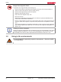
3.3 Using in Ex environments
WARNING
The use of the XTS in potentially explosive atmospheres – Directive 94/9/EC
– is not permitted!
eXtended Transport System Start-Up10
Version: 1.2

Handling
4 Handling
4.1 Transport
• The XTS starter kit may only be transported by qualified personnel and in the manufacturer's original
packaging.
• Avoid shocks, particularly at the corners of the packaging.
• If the packaging is damaged, check the XTS starter kit for visible damage. Inform the transport
company and, if necessary, the manufacturer.
CAUTION
Damage to the device due to improper transport!
When transporting the XTS starter kit ensure that all specifications are met. In particular,
jerky and fast movements should be avoided.
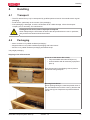
4.2 Packaging
• Motor modules in recyclable cardboard packaging*
• Magnet holders in recyclable cardboard packaging with foam inserts*
• Movers in recyclable cardboard packaging with bubble wrap*
*only single packaging.
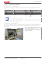
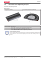
Shipping of the XTS starter kit
Contents of the Starter Kit include
• Fully Assembled and tested XTS (item 4)
• Control Cabinet with all necessary equipment
(item 3)
Both are secured in the shipping crate to prevent
movement during transport.
Warning Pinch Point!
When opening/closing the case keep hands clear of
the area between the lid of the crate (1) and the side
of the crate (2) two People are required to lift/lower
the lid!
eXtended Transport System Start-Up 11
Version: 1.2

Handling
4.3 Storage
Requirement Characteristic value
Climate category 2K3 according to EN 60721
Storage temperature -25°C to +85°C
Permissible relative humidity 15% - 95%, no condensation
Store only in the original recyclable manufacturer's packaging.
4.4 Maintenance / Cleaning
Maintenance
The XTS motor modules are maintenance-free!
WARNING
Observe the ambient commissioning conditions!
Make sure that the XTS is stored and electrically operated only under the specified condi-
tions.
The XTS movers are not maintenance-free!
WARNING
Destruction of the rails!
The guide rollers of movers must be checked at regular intervals. Remove any dirt or other
foreign material that may have accumulated on the guide rollers during operation. Failure to
comply with regular maintenance can lead to increased wear of the guide rollers, as well as
damage to the rails.
Note
Rail maintenance
The rails can be lubricated lightly. This increases the life of the guide rollers. The following
lubricants are suitable for this purpose:
• Vaseline according to DAB 10 (German Pharmacopoeia 10)
• Vaseline spray
• Silicone spray
• PTFE spray
• If the rails are cleaned for maintenance, re-lubricate them with one of the lubricants
listed above. For further specifications please contact the Beckhoff applications depart-
ment.
eXtended Transport System Start-Up12
Version: 1.2

Handling
Cleaning
The XTS modules are sealed according to protection class IP65. They are not protected against aggressive
substances. Clean the modules regularly to protect them against rust and corrosion. Use only Isopropanol.
WARNING
Damage to motor modules
If damage to the motor modules has occurred, please contact Beckhoff Automation GmbH
& Co. KG immediately!
WARNING
Damage to the guide rollers
Make sure that the rails are free from dirt and metallic particles. A dirty rail can significantly
reduce the service life of the guide rollers.
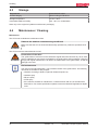
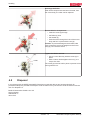
4.4.1 Replacement of the guide rollers
Installation manual
Loosen the roller axel nut
• Use a 1.5mm Allen Key hold to hold the screw
in place. (2)
• Loosen and remove the nut using a 5.5mm
socket wrench/spanner (1)
The Screw (2) must be held in place to prevent it
from turning with the Socket.
Removal of the components
• Pull out the screw that is the shaft of the roller
(2) and take with it
• the Roller (4)
• the washer (5)
• the nut (1)
Caution! When removing the screw (2) be sure to
pull it straight out from the hole in the mover body (6)
in order to prevent damage to the threads. Do not tilt
it.
eXtended Transport System Start-Up 13
Version: 1.2

Handling
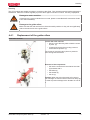
Exchange the Roller
After all the components have been removed, from
the mover body, the roller can be replaced.
Reassemble the Components
• Insert the screw (2) through
• the Roller (4) then
• the washer (5)
• Push the screw through the hole of the mover
body and fix it in place with the nut (6)
Caution! To prevent damage to the threads, take
care to insert the screw (2) straight into the mover
body (6). Do not tilt the screw.
Tighten the Roller axel nut.
• Use a 1.5mm Allen key hold the screw (2) in
place.
• With a 5.5mm Socket tighten the nut (1) to a
torque of 2.4Nm
The screw (2) must be held in place to prevent it from
turning with the nut.
4.5 Disposal
In accordance with the WEEE 2002/96/EC Directives we take old devices and accessories back for
professional disposal, provided the transport costs are taken over by the sender. Send the devices with the
note “For disposal” to:
Beckhoff Automation GmbH & Co. KG
Service-Center
Stahlstraße 31
33415 Verl
eXtended Transport System Start-Up14
Version: 1.2

Product identification
5 Product identification
5.1 Scope of supply
Check the completeness of the delivery against your delivery note.
Missing parts or damage should be recorded immediately and reported to the carrier, the insurance and/or
Beckhoff Automation GmbH & Co. KG.
The standard scope of supply includes:
• XTS-Starter Kit
• Control cabinet
• Connection cables
• Control PC
• Switch mode power supply units for 24 V and 48 V
• Software licenses (TwinCAT/TC3/XTS Extension)
• Commissioning of the XTS (this manual)
5.2 Type label
eXtended Transport System Start-Up 15Version: 1.2

Product identification
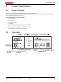
5.3 Type key
*Content of the XTS-Starterkit
eXtended Transport System Start-Up16
Version: 1.2

Product identification
*Content of the XTS-Starterkit
eXtended Transport System Start-Up 17
Version: 1.2

Technical description
6 Technical description
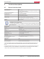
6.1 General technical data
Environmental influences XTS
Ambient temperature -10 °C – +40 °C
If ambient temperatures exceeding +40 °C are expected, it is essential to contact
the Beckhoff applications department.
Transport and storage temperature -25 °C - +85 °C
Permissible relative humidity 15 % - +95 %, no condensation
Contamination level EN 60204 / EN 50178 Level 2
Corrosion protection Normally not required. Under extreme operating conditions, special measures
may be imposed by the production.
Installation altitude Between 1000 m and 2500 m, the performance reduces by 1.5% per 100 m.
Installation position Vertical installation position of the starter kit and housing
Other installation positions are possible for further individual XTS components
Ventilation XTS via convection
Protection class IP65
Note
Ventilation of the machine bed!
To improve system utilization, it is strongly recommend to actively or passively cool the ma-
chine bed of the XTS. For further information on cooling please contact the Beckhoff appli-
cations department!
System properties XTS
Max. force 100 N at standstill
Payload 80 N at 2 m/s
Continuous force 30 N (at approx. 30 °C temperature increase between motor / mounting frame)
Velocity 4 m/s at 48 V
DC
supply
Acceleration > 100 m/s² (without payload)
Synchronization accuracy < ± 0.15
1*)
mm at 1.5 m/s within a straight module
Absolute accuracy < ± 0.25
2*)
mm within a straight module
Repeatability (unidirectional) < ± 10 µm (standstill)
Mover length 50 mm in direction of movement (AT9011)
Mover weight Approx. 350 g (complete mover without attachments)
Maximum system length > 10 m (dependent on computing power, no system limit)
Occurring temperature during operation /
storage temperature
0…< +105 °C
3*)
/ -25 °C…+85 °C
Protection class IP 65
Approvals CE
Vibration/shock resistance Conforms to EN60068-2-6/EN 60068-2-27
EMC immunity/emission Conforms to EN61000-6-2/EN 61000-6-4
1*)
The synchronization accuracy is primarily dependent on the mechanical stiffness and the load on the
mover. The controller setting and the mechanical offset between the modules must also be taken into
account.
2*)
Typically achievable absolute accuracy; this may be exceeded in case of significant thermal warming of
the module (∆ϑ ≥ 30°C) or lack of parallelism or orthogonality of the encoder flag to the motor module.
3*)
Please note the special safety instructions for the XTS on page 8 of this manual!
eXtended Transport System Start-Up18
Version: 1.2

Technical description
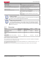
Electrical data XTS
Supply voltage Control voltage 24 V
DC
, power supply 50 V
DC
Current consumption Power supply: 16 A rated current
Power consumption control voltage (24 V) Motor modules: 30 W/m (communication, electronics,
displacement measurement)
Length per infeed Typically 1 m – max. 3 m (depending on computing power)
Power consumption per mover approx. 30 W at 2 m/s constant speed
approx. 60 W at 4 m/s constant speed
approx. 60 W at a peak acceleration of 10 m/s² and a mass
of 1 kg
approx. 300 W at a peak acceleration of 50 m/s² and a
mass of 1 kg
Note
Length per infeed!
The length per infeed is application-dependent. For precise dimensioning of the power sup-
ply please contact the Beckhoff applications department.
Note
Energy recovery from the XTS
The XTS is capable of energy recovery. If kinetic energy is fed back during an emergency
stop, measures should be taken to avoid voltage overshoot, and associated premature
auto-shutdown of the motor modules. For further information please contact the Beckhoff
applications department.
6.1.1 Dimensions
Module Width at the ma-
chine bed
Width at the
track connection
Height Depth
Straight motor module
AT2001-0250
39.1 mm 22.1 mm 96 mm 250 mm
Straight line motor module with power
supply
AT2001-0250
39.1 mm 22.1 mm 96 mm 250 mm
Curved motor module 180° (clothoid)
AT2050-0500
39.1 mm 22.1 mm 306.5 mm 204.2 mm
Distance between movers and modules
The air gap between the magnet and the motor should by 0.85 mm on each side. Important: The magnets
must not touch the motor modules of the XTS!
The air gap between the encoder flag and the sensor should be 0.9 mm. A tolerance range of 0.4 mm – 1.4
mm applies (as of December 2015).
Important: Under no circumstances must the encoder flag touch the sensors of the motor modules!
eXtended Transport System Start-Up 19
Version: 1.2

Technical description
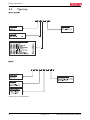
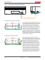
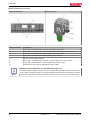
6.1.2 Connection diagram XTS-Infeed
24V Power supply
48V
GND
24V
PE connection port
of the module body
EtherCAT
line
48V Power supply
Control cabinet earth
Circuit diagram 48 V negative not grounded:
Do not ground the negative side of the 48V DC Bus
Power Supply! The adjacent diagram describes the
current distribution in the individual conductors. Inside
the module the negative 24V and negative 48V
cables are connected together. If the 48V minus is
not grounded the current for each circuit remains on
its conductors. The current for the 24V control power
remains on the 0.75mm wires to and from the
module. The current for the 48V power remains on
the 2.5mm 48V wires to and from the module. The
grounding of the DC Bus circuit is not necessary. The
EN60204-1 Standard chapter 9.4.3.1 (ground faults)
describes that the control circuits must be grounded
to ensure a machine cannot start with a broken cable.
Load circuits are not affected.
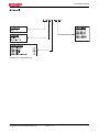
Circuit diagram 48 V minus grounded:
If the negative side of the 48V power supply is
grounded, the following situation occurs as described
by the adjacent diagram. Again, the -48V and -24V
lines are connected internally in the modules. If the
negative side of the 48V power supply is also
grounded, -24V wire (0.75mm) and the -48V wire
(2.5mm) act in parallel for the return path. This will
overload the -24V (0.75mm) wire. The +48V wire
(2.5mm) will carry the 48V load circuit current to the
module, the +24V wire (0.75mm) will carry the 24V
Control circuit current to the module. On the return
side, the -24V (0.75mm) wire will carry half of the
sum of the 48V load circuit current and the 24V
control circuit current. The -48V (2.5mm) wire will
carry the other half of the sum of the currents. The
0.75mm wire does have a slightly higher resistance
(0.042Ohm/m) than the 2.5mm (0.013Ohm/m) wire
but the difference is so small it can be omitted.
eXtended Transport System Start-Up20
Version: 1.2
Page is loading ...
Page is loading ...
Page is loading ...
Page is loading ...
Page is loading ...
Page is loading ...
Page is loading ...
Page is loading ...
Page is loading ...
Page is loading ...
Page is loading ...
Page is loading ...
Page is loading ...
Page is loading ...
Page is loading ...
Page is loading ...
Page is loading ...
Page is loading ...
Page is loading ...
Page is loading ...
Page is loading ...
Page is loading ...
Page is loading ...
Page is loading ...
Page is loading ...
Page is loading ...
-
 1
1
-
 2
2
-
 3
3
-
 4
4
-
 5
5
-
 6
6
-
 7
7
-
 8
8
-
 9
9
-
 10
10
-
 11
11
-
 12
12
-
 13
13
-
 14
14
-
 15
15
-
 16
16
-
 17
17
-
 18
18
-
 19
19
-
 20
20
-
 21
21
-
 22
22
-
 23
23
-
 24
24
-
 25
25
-
 26
26
-
 27
27
-
 28
28
-
 29
29
-
 30
30
-
 31
31
-
 32
32
-
 33
33
-
 34
34
-
 35
35
-
 36
36
-
 37
37
-
 38
38
-
 39
39
-
 40
40
-
 41
41
-
 42
42
-
 43
43
-
 44
44
-
 45
45
-
 46
46


Ask a question and I''ll find the answer in the document
Finding information in a document is now easier with AI
Related papers
-
 Beckhoff ATH2000-0250 Operating Instructions Manual
-
 Beckhoff XTS Standard Operating Instructions Manual
-
 Beckhoff MES Documentation
-
 Beckhoff C9900-M994 Installation and Operating Instruction
-
 Beckhoff C9900-M900 Installation and Operating Instruction
-
 Beckhoff XPlanar Operating Instructions Manual
-
 Beckhoff EM2042 Documentation
-
 Beckhoff CX2550-0279 User manual
-
 Beckhoff KM2042 Documentation
-
 Beckhoff CX2500-0030 User manual


Other documents
-
WALI GSDM003 User manual
-
Siemens Built-in wine cooler Supplemental
-
 ShelterLogic 90490 User guide
-
 Xtreme Garage PB-40001G Operating instructions
-
 Mercury Floor Machines 90-2000WH Safety, Operation And Maintenance Manual With Parts List
-
 Ironton Mini Air Mover Carpet/Floor Blower Owner's manual
-
 U.S.SAWS 30178 Installation guide
-
IFM SBU325 Operating instructions
-
 Corpus.e Lightbeam User manual
-
HellermannTyton Force Measurement Device CPK Owner's manual


