Page is loading ...

Eaton
®
9130 UPS
700/3000 VA
User's Guide

Requesting a Declaration of Conformity
Units that are labeled with a CE mark comply with the following harmonized standards and EU directives:
l
Harmonized Standards: EN 62040-1-1 and EN 62040-2; IEC 60950-1
l
EU Directives:
73/23/EEC, Council Directive on equipment designed for use within certain voltage limits
93/68/EEC, Amending Directive 73/23/EEC
2004/108/EEC, Council Directive relating to electromagnetic compatibility
The EC Declaration of Conformity is available upon request for products with a CE mark. For copies of the EC
Declaration of Conformity, contact:
Eaton Power Quality Oy
Koskelontie 13
FIN-02920 Espoo
Finland
Phone: +358-9-452 661
Fax: +358-9-452 665 68
Eaton, FERRUPS, Network Card-MS, and Intelligent Power Protector are registered trademarks of Eaton
Corporation or its subsidiaries and affiliates. IBM and AS/400 is a registered trademark International Business
Machines Corporation. Microsoft and Windows are registered trademarks of Microsoft Corporation in the
United States and other countries. National Electrical Code and NEC are registered trademarks of National Fire
Protection Association, Inc. Phillips and Pozidriv are registered trademarks of Phillips Screw Company. All
other trademarks are property of their respective companies.
Copyright 2011 Eaton Corporation, Raleigh, NC, USA. All rights reserved. No part of this document may be
reproduced in any way without the express written approval of Eaton Corporation.

Class A EMC Statements
FCC Part 15
This equipment has been tested and found to comply with the limits for a Class A digital device, pursuant to
part 15 of the FCC Rules. These limits are designed to provide reasonable protection against harmful
interference when the equipment is operated in a commercial environment. This equipment generates, uses,
and can radiate radio frequency energy and, if not installed and used in accordance with the instruction manual,
may cause harmful interference to radio communications. Operation of this equipment in a residential area is
likely to cause harmful interference in which case the user will be required to correct the interference at his
own expense
EN 62040-2
Some configurations are classified under EN 62040-2 as “Category C2 UPS.” For these configurations, the
following applies:
WARNING
This is a category C2 UPS product. In a residential environment, this product may cause radio
interference, in which case the user may be required to take additional measures.

Special Symbols
The following are examples of symbols used on the UPS or accessories to alert you to important information:
RISK OF ELECTRIC SHOCK - Observe the warning associated with the risk
of electric shock symbol.
CAUTION: REFER TO OPERATOR'S MANUAL - Refer to your operator's
manual for additional information, such as important operating and
maintenance instructions.
This symbol indicates that you should not discard the UPS or the UPS
batteries in the trash. This product contains sealed, lead-acid batteries and
must be disposed of properly. For more information, contact your local
recycling/reuse or hazardous waste center.
This symbol indicates that you should not discard waste electrical or
electronic equipment (WEEE) in the trash. For proper disposal, contact your
local recycling/reuse or hazardous waste center.

Eaton 9130 700/3000 VA UPS User’s Guide 164201718—Rev 7 www.eaton.com/powerquality i
Table of Contents
1 INTRODUCTION . . . . . . . . . . . . . . . . . . . . . . . . . . . . . . . . . . . . . . . . . . . . . . . . . . . . . . . . . . . . . . . . . . . . . . . . 1
2 SAFETY WARNINGS . . . . . . . . . . . . . . . . . . . . . . . . . . . . . . . . . . . . . . . . . . . . . . . . . . . . . . . . . . . . . . . . . . . . 3
3 INSTALLATION . . . . . . . . . . . . . . . . . . . . . . . . . . . . . . . . . . . . . . . . . . . . . . . . . . . . . . . . . . . . . . . . . . . . . . . . . 12
Inspecting the Equipment . . . . . . . . . . . . . . . . . . . . . . . . . . . . . . . . . . . . . . . . . . . . . . . . . . . . . . . . . 12
Unpacking the Cabinet. . . . . . . . . . . . . . . . . . . . . . . . . . . . . . . . . . . . . . . . . . . . . . . . . . . . . . . . . . . . 12
Checking the Accessory Kit . . . . . . . . . . . . . . . . . . . . . . . . . . . . . . . . . . . . . . . . . . . . . . . . . . . . . . . . 13
Rackmount Installation . . . . . . . . . . . . . . . . . . . . . . . . . . . . . . . . . . . . . . . . . . . . . . . . . . . . . . . . . . . 13
Checking the Rail Kit Accessories . . . . . . . . . . . . . . . . . . . . . . . . . . . . . . . . . . . . . . . . . . . . . . . 13
Tools Required . . . . . . . . . . . . . . . . . . . . . . . . . . . . . . . . . . . . . . . . . . . . . . . . . . . . . . . . . . . . . 14
Rackmount Setup . . . . . . . . . . . . . . . . . . . . . . . . . . . . . . . . . . . . . . . . . . . . . . . . . . . . . . . . . . . 14
Rackmount Wiring Installation . . . . . . . . . . . . . . . . . . . . . . . . . . . . . . . . . . . . . . . . . . . . . . . . . . . . . . 16
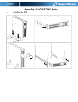
Installing the UPS . . . . . . . . . . . . . . . . . . . . . . . . . . . . . . . . . . . . . . . . . . . . . . . . . . . . . . . . . . . 16
Connecting the EBM(s) . . . . . . . . . . . . . . . . . . . . . . . . . . . . . . . . . . . . . . . . . . . . . . . . . . . . . . . 18
Tower Installation . . . . . . . . . . . . . . . . . . . . . . . . . . . . . . . . . . . . . . . . . . . . . . . . . . . . . . . . . . . . . . . 20
Tower Wiring Installation . . . . . . . . . . . . . . . . . . . . . . . . . . . . . . . . . . . . . . . . . . . . . . . . . . . . . . . . . . 20
Installing the UPS . . . . . . . . . . . . . . . . . . . . . . . . . . . . . . . . . . . . . . . . . . . . . . . . . . . . . . . . . . . 21
Connecting the EBM(s) . . . . . . . . . . . . . . . . . . . . . . . . . . . . . . . . . . . . . . . . . . . . . . . . . . . . . . . 22
UPS Initial Startup . . . . . . . . . . . . . . . . . . . . . . . . . . . . . . . . . . . . . . . . . . . . . . . . . . . . . . . . . . . . . . . 24
4 OPERATION. . . . . . . . . . . . . . . . . . . . . . . . . . . . . . . . . . . . . . . . . . . . . . . . . . . . . . . . . . . . . . . . . . . . . . . . . . . . 26
Control Panel Functions. . . . . . . . . . . . . . . . . . . . . . . . . . . . . . . . . . . . . . . . . . . . . . . . . . . . . . . . . . . 26
Changing the Language. . . . . . . . . . . . . . . . . . . . . . . . . . . . . . . . . . . . . . . . . . . . . . . . . . . . . . . 27
Display Functions . . . . . . . . . . . . . . . . . . . . . . . . . . . . . . . . . . . . . . . . . . . . . . . . . . . . . . . . . . . 27
User Settings. . . . . . . . . . . . . . . . . . . . . . . . . . . . . . . . . . . . . . . . . . . . . . . . . . . . . . . . . . . . . . . 28
Operating Modes. . . . . . . . . . . . . . . . . . . . . . . . . . . . . . . . . . . . . . . . . . . . . . . . . . . . . . . . . . . . . . . . 31
Normal Mode . . . . . . . . . . . . . . . . . . . . . . . . . . . . . . . . . . . . . . . . . . . . . . . . . . . . . . . . . . . . . . 31
Battery Mode . . . . . . . . . . . . . . . . . . . . . . . . . . . . . . . . . . . . . . . . . . . . . . . . . . . . . . . . . . . . . . 31
Bypass Mode . . . . . . . . . . . . . . . . . . . . . . . . . . . . . . . . . . . . . . . . . . . . . . . . . . . . . . . . . . . . . . 31
Standby Mode. . . . . . . . . . . . . . . . . . . . . . . . . . . . . . . . . . . . . . . . . . . . . . . . . . . . . . . . . . . . . . 32
UPS Startup and Shutdown . . . . . . . . . . . . . . . . . . . . . . . . . . . . . . . . . . . . . . . . . . . . . . . . . . . . . . . . 32
Starting the UPS . . . . . . . . . . . . . . . . . . . . . . . . . . . . . . . . . . . . . . . . . . . . . . . . . . . . . . . . . . . . 32
Starting the UPS on Battery . . . . . . . . . . . . . . . . . . . . . . . . . . . . . . . . . . . . . . . . . . . . . . . . . . .32
UPS Shutdown . . . . . . . . . . . . . . . . . . . . . . . . . . . . . . . . . . . . . . . . . . . . . . . . . . . . . . . . . . . . . 33
Transferring the UPS Between Modes . . . . . . . . . . . . . . . . . . . . . . . . . . . . . . . . . . . . . . . . . . . . . . .33
Retrieving the Event Log . . . . . . . . . . . . . . . . . . . . . . . . . . . . . . . . . . . . . . . . . . . . . . . . . . . . . . . . . . 33
Logic Power Off. . . . . . . . . . . . . . . . . . . . . . . . . . . . . . . . . . . . . . . . . . . . . . . . . . . . . . . . . . . . . . . . . 33
Setting Power Strategy . . . . . . . . . . . . . . . . . . . . . . . . . . . . . . . . . . . . . . . . . . . . . . . . . . . . . . . . . . . 34
Configuring Bypass Settings . . . . . . . . . . . . . . . . . . . . . . . . . . . . . . . . . . . . . . . . . . . . . . . . . . . . . . . 34
Configuring Load Segments . . . . . . . . . . . . . . . . . . . . . . . . . . . . . . . . . . . . . . . . . . . . . . . . . . . . . . . 35
Configuring Battery Settings . . . . . . . . . . . . . . . . . . . . . . . . . . . . . . . . . . . . . . . . . . . . . . . . . . . . . . . 36
Configuring the UPS for EBMs . . . . . . . . . . . . . . . . . . . . . . . . . . . . . . . . . . . . . . . . . . . . . . . . . 36
Running Automatic Battery Tests . . . . . . . . . . . . . . . . . . . . . . . . . . . . . . . . . . . . . . . . . . . . . . . 36
Configuring Automatic Restart . . . . . . . . . . . . . . . . . . . . . . . . . . . . . . . . . . . . . . . . . . . . . . . . . 37

Table of Contents
Eaton 9130 700/3000 VA UPS User’s Guide 164201718—Rev 7 www.eaton.com/powerquality ii
5 COMMUNICATION. . . . . . . . . . . . . . . . . . . . . . . . . . . . . . . . . . . . . . . . . . . . . . . . . . . . . . . . . . . . . . . . . . . . . . 38
Installing Communication Options and Control Terminals. . . . . . . . . . . . . . . . . . . . . . . . . . . . . . . . . 38
Communication Options . . . . . . . . . . . . . . . . . . . . . . . . . . . . . . . . . . . . . . . . . . . . . . . . . . . . . . . . . . 38
RS-232 and USB Communication Ports . . . . . . . . . . . . . . . . . . . . . . . . . . . . . . . . . . . . . . . . . . 39
Connectivity Cards . . . . . . . . . . . . . . . . . . . . . . . . . . . . . . . . . . . . . . . . . . . . . . . . . . . . . . . . . . 39
Remote Emergency Power-off . . . . . . . . . . . . . . . . . . . . . . . . . . . . . . . . . . . . . . . . . . . . . . . . . 40
Forced to Bypass State . . . . . . . . . . . . . . . . . . . . . . . . . . . . . . . . . . . . . . . . . . . . . . . . . . . . . . . 41
Relay Output Contacts . . . . . . . . . . . . . . . . . . . . . . . . . . . . . . . . . . . . . . . . . . . . . . . . . . . . . . . 41
Programmable Signal Inputs . . . . . . . . . . . . . . . . . . . . . . . . . . . . . . . . . . . . . . . . . . . . . . . . . . . 42
Power Management and Protection Software . . . . . . . . . . . . . . . . . . . . . . . . . . . . . . . . . . . . . . . . . 43
6 MAINTENANCE . . . . . . . . . . . . . . . . . . . . . . . . . . . . . . . . . . . . . . . . . . . . . . . . . . . . . . . . . . . . . . . . . . . . . . . . 44
UPS and Battery Care . . . . . . . . . . . . . . . . . . . . . . . . . . . . . . . . . . . . . . . . . . . . . . . . . . . . . . . . . . . . 44
Storing the UPS and Batteries . . . . . . . . . . . . . . . . . . . . . . . . . . . . . . . . . . . . . . . . . . . . . . . . . . . . . . 44
When to Replace Batteries . . . . . . . . . . . . . . . . . . . . . . . . . . . . . . . . . . . . . . . . . . . . . . . . . . . . . . . . 44
Replacing Batteries . . . . . . . . . . . . . . . . . . . . . . . . . . . . . . . . . . . . . . . . . . . . . . . . . . . . . . . . . . . . . . 44
Replacing Rackmount UPS Internal Batteries . . . . . . . . . . . . . . . . . . . . . . . . . . . . . . . . . . . . . . 45
Replacing Tower UPS Internal Batteries . . . . . . . . . . . . . . . . . . . . . . . . . . . . . . . . . . . . . . . . . . 47
Replacing Rackmount EBMs. . . . . . . . . . . . . . . . . . . . . . . . . . . . . . . . . . . . . . . . . . . . . . . . . . . 50
Replacing Tower EBMs. . . . . . . . . . . . . . . . . . . . . . . . . . . . . . . . . . . . . . . . . . . . . . . . . . . . . . .51
Testing New Batteries . . . . . . . . . . . . . . . . . . . . . . . . . . . . . . . . . . . . . . . . . . . . . . . . . . . . . . . . . . . . 52
Recycling the Used Battery or UPS. . . . . . . . . . . . . . . . . . . . . . . . . . . . . . . . . . . . . . . . . . . . . . . . . . 52
Updating the UPS Firmware . . . . . . . . . . . . . . . . . . . . . . . . . . . . . . . . . . . . . . . . . . . . . . . . . . . . . . . 52
7 SPECIFICATIONS . . . . . . . . . . . . . . . . . . . . . . . . . . . . . . . . . . . . . . . . . . . . . . . . . . . . . . . . . . . . . . . . . . . . . . . 53
Rear Panels . . . . . . . . . . . . . . . . . . . . . . . . . . . . . . . . . . . . . . . . . . . . . . . . . . . . . . . . . . . . . . . . . . . . 69
8 TROUBLESHOOTING . . . . . . . . . . . . . . . . . . . . . . . . . . . . . . . . . . . . . . . . . . . . . . . . . . . . . . . . . . . . . . . . . . . . 83
Typical Alarms and Conditions. . . . . . . . . . . . . . . . . . . . . . . . . . . . . . . . . . . . . . . . . . . . . . . . . . . . . . 83
Alarm or Condition. . . . . . . . . . . . . . . . . . . . . . . . . . . . . . . . . . . . . . . . . . . . . . . . . . . . . . . . . . . 83
Silencing the Alarm . . . . . . . . . . . . . . . . . . . . . . . . . . . . . . . . . . . . . . . . . . . . . . . . . . . . . . . . . . . . . . 85
Service and Support. . . . . . . . . . . . . . . . . . . . . . . . . . . . . . . . . . . . . . . . . . . . . . . . . . . . . . . . . . . . . . 85
9 WARRANTY. . . . . . . . . . . . . . . . . . . . . . . . . . . . . . . . . . . . . . . . . . . . . . . . . . . . . . . . . . . . . . . . . . . . . . . . . . . . 87

Eaton 9130 700/3000 VA UPS User’s Guide 164201718—Rev 7 www.eaton.com/powerquality 1
Chapter 1 Introduction
The Eaton
®
9130 uninterruptible power system (UPS), protects your sensitive electronic equipment from the
most common power problems, including power failures, power sags, power surges, brownouts, line noise,
high voltage spikes, frequency variations, switching transients, and harmonic distortion.
Power outages can occur when you least expect it and power quality can be erratic. These power problems
have the po
tential to corrupt critical data, destroy unsaved work sessions, and damage hardware – causing
hours of lost productivity and expensive repairs.
With the Eaton 9130, you can safely eliminate the effects of power disturbances and guard the integrity of
your equipment. Providing outstanding performance and reliability, the Eaton 9130's unique benefits include:
l
True online double-conversion technology with high power density, utility frequency independence, and
generator compatibility.
l
Advanced Battery Management (ABM
®
)technology that uses advanced battery management to increase
service life, optimize recharge time, and provide a warning before the end of useful battery life.
l
Selectable High Efficiency mode of operation.
l
Rackmount models in a space-optimizing 2U size that fits any standard 19" rack.
l
Standard communication options: one RS-232 communication port, one USB communication port, and relay
output contacts.
l
Optional connectivity cards with enhanced communication capabilities.
l
Extended runtime with up to four Extended Battery Modules (EBMs) per UPS.
l
Firmware that is easily upgradable without a service call.
l
Emergency shutdown control through the Remote Emergency Power-off (REPO) port.
l
Backed by worldwide agency approvals.
Figure 1 shows the Eaton 9130 rackmount UPS, and Figure 2 shows the optional rackmount EBM.
Figure 1. The Eaton 9130 Rackmount UPS
Figure 2. The Eaton 9130 Rackmount EBM


Eaton 9130 700/3000 VA UPS User’s Guide 164201718—Rev 7 www.eaton.com/powerquality 3
Chapter 2 Safety Warnings
IMPORTANT SAFETY INSTRUCTIONS — SAVE THESE INSTRUCTIONS
This manual contains important instructions that you should follow during installation and
maintenance of the UPS and batteries. Please read all instructions before operating the equipment
and save this manual for future reference.
DANGER
This UPS contains LETHAL VOLTAGES. All repairs and service should be performed by
AUTHORIZED SERVICE PERSONNEL ONLY. There are NO USER SERVICEABLE PARTS inside the
UPS.
WARNING
l
This UPS contains its own energy source (batteries). The UPS output may carry live voltage
even when the UPS is not connected to an AC supply.
l
To reduce the risk of fire or electric shock, install this UPS in a temperature and humidity
controlled, indoor environment, free of conductive contaminants. Ambient temperature must
not exceed 40C (104F). Do not operate near water or excessive humidity (90% maximum).
l
To reduce the risk of fire, connect only to a circuit provided with branch circuit overcurrent
protection in accordance with the National Electrical Code (NEC), ANSI/NFPA 70.
l
Output overcurrent protection and disconnect switch must be provided by others.
l
To comply with international standards and wiring regulations, the sum of the leakage current of
the UPS and the total equipment connected to the output of this UPS must not have an earth
leakage current greater than 3.5
milliamperes.
l
If installing an optional rackmount Extended Battery Module (EBM), install the EBM(s) directly
below the UPS so that all wiring between the cabinets is installed behind the front covers and is
inaccessible to users. The maximum number of EBM(s) per UPS is four.
l
If the UPS requires any type of transportation, verify that the UPS is unplugged and turned off
and then disconnect the UPS internal battery connector (see
Figure 24 on page 46 for
rackmount models or Figure 26 on page 48 for tower models).
CAUTION
l
Batteries can present a risk of electrical shock or burn from high short-circuit current. Observe
proper precautions. Servicing should be performed by qualified service personnel
knowledgeable of batteries and required precautions. Keep unauthorized personnel away from
batteries.
l
Proper disposal of batteries is required. Refer to your local codes for disposal requirements.
l
Never dispose of batteries in a fire. Batteries may explode when exposed to flame.

Safety Warnings
Eaton 9130 700/3000 VA UPS User’s Guide 164201718—Rev 7 www.eaton.com/powerquality 4
Tarkeita Turvaohjeita
TÄRKEITÄ TURVAOHJEITA - SUOMI — SÄILYTÄ NÄMÄ OHJEET
Tämä käyttöohje sisältää tärkeitä ohjeita, joita on noudatettava UPS-virtalähteen ja akkujen
asennuksen ja huollon yhteydessä. Lue kaikki ohjeet ennen laitteiston käyttöä ja säilytä ohje
myöhempää tarvetta varten.
VAARA
Tämä UPS sisältää HENGENVAARALLISIA JÄNNITTEITÄ. Kaikki korjaukset ja huollot on jätettävä
VAIN VALTUUTETUN HUOLTOHENKILÖN TOIMEKSI. UPS ei sisällä MITÄÄN KÄYTTÄJÄN
HUOLLETTAVIA OSIA.
VAROITUS
l
Tässä UPS-virtalähteessä on oma energianlähde (akut). UPS-virtalähteen lähdössä voi olla
jännite, vaikka UPS-virtalähdettä ei ole kytketty verkkovirtaan.
l
Vähentääksesi tulipalon ja sähköiskun vaaraa asenna tämä UPS sisätiloihin, joissa lämpötila ja
kosteus on säädettävissä ja joissa ei ole virtaa johtavia epäpuhtauksia. Ympäristön lämpötila ei
saa ylittää 40
°C. Älä käytä lähellä vettä ja vältä kosteita tiloja (95 % maksimi).
l
Pienennä tulipalon vaaraa kytkemällä vain piiriin, jossa on 100 ampeerin maksimihaarapiirin
ylivirtasuoja kansallisen sähkölainsäädännön (ANSI/NFPA 70) mukaan.
l
Muiden on toimitettava lähdön ylivirtasuoja ja irtikytkentäkytkin.
l
Kansainväliset normit ja johdotusmääräykset vaativat, että kaikkien tämän UPS-laitteen
ulostulokytkentöjen yhteinen maavuotovirta ei ylitä 3,5 milliampeeria (mA).
l
Jos asennat valinnaisia räkkiasenteisia EBM, asenna EBM suoraan UPS:n alapuolelle niin, että
laitteiden väliset johdotukset on asennettu kotelon etuosan taakse, jotta käyttäjä ei pääse niihin
käsiksi. Maksimi on EBM yksikköä per UPS.
l
Jos UPS:ia on kuljetettava, on varmistettava, että UPS on irrotettu verkosta ja sammutettu ja että
sisäiset akut on kytketty irti (katso Kuva 24 ja lue räkkimalleista sivulta 43 ja tornimalleista Kuva
26-sivulta 46,
VARO
l
Akut voivat aiheuttaa sähköiskun tai palovammojen vaaran johtuen suuresta oikosulkuvirrasta.
Noudata kaikkia asianmukaisia varotoimia. Laitteen saa huoltaa vain ammattitaitoinen
huoltohenkilökunta, joka tuntee akut ja niihin liittyvät varotoimet. Älä päästä valtuuttamatonta
henkilöstöä lähelle akkuja.
l
Akusto täytyy hävittää säädösten mukaisella tavalla. Noudata paikallisia määräyksiä.
l
Älä koskaan heitä akkuja tuleen. Ne voivat räjähtää.

Safety Warnings
Eaton 9130 700/3000 VA UPS User’s Guide 164201718—Rev 7 www.eaton.com/powerquality 5
Consignes de sécurité
CONSIGNES DE SÉCURITÉ IMPORTANTES — CONSERVER CES INSTRUCTIONS
Ce manuel comporte des instructions importantes que vous êtes invité à suivre lors de toute
procédure d'installation et de maintenance des batteries et de l'onduleur. Veuillez consulter
entièrement ces instructions avant de faire fonctionner l'équipement et conserver ce manuel afin
de pouvoir vous y reporter ultérieurement.
DANGER!
Cet onduleur contient des TENSIONS MORTELLES. Toute opération d'entretien et de réparation
doit être EXCLUSIVEMENT CONFIÉE A UN PERSONNEL QUALIFIÉ AGRÉÉ. AUCUNE PIÈCE
RÉPARABLE PAR L'UTILISATEUR ne se trouve dans l'onduleur.
AVERTISSEMENT!
l
Cette onduleur possède sa propre source d'alimentation (batteries). Il est possible que la sortie
de l'onduleur soit sous tension même lorsque l'onduleur n'est pas connectée à une
alimentation CA.
l
Pour réduire les risques d'incendie et de décharge électrique, installer l'onduleur uniquement à
l'intérieur, dans un lieu dépourvu de matériaux conducteurs, où la température et l'humidité
ambiantes sont contrôlées. La température ambiante ne doit pas dépasser 40 °C. Ne pas utiliser
à proximité d'eau ou dans une atmosphère excessivement humide (95
% maximum).
l
Afin de réduire les risques d'incendie, ne raccordez qu'à un circuit muni d'une protection de
surintensité du circuit de dérivation maximum de 100 ampères conformément au NEC (Code
Électrique National) des États-Unis, ANSI/NFPA
70.
l
La protection de surintensité de sortie ainsi que le sectionneur doivent être fournis par des tiers.
l
Afin d'être conforme aux normes et règlements internationaux de câblage, le courant de fuite à
la terre de la totalité du matériel branché sur la sortie de l'onduleur ne doit pas dépasser 3,5
mA.
l
Si vous installez un ou des châssis optionnel EBMs, installez-les EBM directement en dessous
de l'onduleur de sorte que tout le câblage entre les modules soit installé derrière les couvercles
et soit inaccessible aux utilisateurs. Le nombre maximum de EBM(s) par UPS est de quatre.
l
Si l'onduleur doit être transporté, vérifiez qu'il est débranché et arrêté avant de déconnecter le
connecteur interne de la batterie (voir Figure 24 à la page 46 pour les modèles pour baie ou
Figure 26 à la page 48 pour des modèles type tour).
ATTENTION!
l
Les batteries peuvent présenter un risque de choc électrique ou de brûlure provenant d'un
courant de court-circuit haute intensité. Observez les précautions appropriées. L'entretien doit
être réalisé par du personnel qualifié connaissant bien les batteries et les précautions
nécessaires. N'autorisez aucun personnel non qualifié à manipuler les batteries.
l
Une mise au rebut réglementaire des batteries est obligatoire. Consulter les règlements en
vigueur dans votre localité.
l
Ne jamais jeter les batteries au feu. L'exposition aux flammes risque de les faire exploser.

Safety Warnings
Eaton 9130 700/3000 VA UPS User’s Guide 164201718—Rev 7 www.eaton.com/powerquality 6
Sicherheitswarnungen
WICHTIGE SICHERHEITSANWEISUNGEN — AUFBEWAREN
Dieses Handbuch enthält wichtige Anweisungen, die Sie während der Installation und Wartung
des USV (Unterbrechungsfreies Stromversorgungssystem) und der Batterien befolgen müssen.
Bitte lesen Sie alle Anweisungen des Handbuches bevor sie mit dem Gerät arbeiten. Bewaren Sie
das Handbuch zum Nachlesen auf.
WARNUNG
Die USV führt lebensgefährliche Spannungen. Alle Reparatur- und Wartungsarbeiten sollten nur
von Kundendienstfachleuten durchgeführt werden. Die USV enthält keine vom Benutzer zu
wartenden Komponenten.
ACHTUNG
l
Dieses USV (Unterbrechungsfreies Stromversorgungssystem) enthält eine eigene
Energiequelle (Batterien). Der USV-Ausgang kann Spannung führen, auch wenn das USV nicht
an eine Wechselstromquelle angeschlossen ist.
l
Um die Brand– oder Elektroschockgefahr zu verringern, diese USV nur in Gebäuden mit
kontrollierter Temperatur und Luftfeuchtigkeit installieren, in denen keine leitenden
Schmutzstoffen vorhanden sind. Die Umgebungstemperatur darf 40°C nicht übersteigen. Die
USV nicht in der Nähe von Wasser oder in extrem hoher Luftfeuchtigkeit (max.
95 %) betreiben.
l
Um die Brandgefahr zu verringern, nur an eine Leitung anschließen, die mit einem
Überlaststromschutz von maximal 100 Ampere in Übereinstimmung mit dem NEC, ANSI/
NFPA
70 ausgestattet ist.
l
Der Ausgangs-Überlaststromschutz und der Trennschalter müssen von anderen Herstellern
geliefert werden.
l
Um internationale Normen und Verdrahtungsvorschriften zu erfüllen, dürfen die an den Ausgang
dieser USV angeschlossenen Geräte zusammen einen Erdableitstrom von insgesamt
3,5 Milliampere nicht überschreiten.
l
Im Falle der Installation optionaler Rackmount EBMs in einem Rack sollte die Installation direkt
unterhalb der USV erfolgen, damit alle Kabel zwischen den Gehäusen hinter den Frontblenden
und für Benutzer unzugänglich verlegt werden können. Es können maximal vier EBMs je USV
installiert werden.
l
Vergewissern Sie sich vor dem Transport der USV, dass die USV von der Stromversorgung
getrennt und ausgeschaltet ist. Trennen Sie anschließend den Anschluss der internen
USV-Batterie (siehe Abbildung 24 auf Seite 47 für im Rack montierte Modelle oder Abbildung 26
auf Seite 49 für Tower-Modelle).

Safety Warnings
Eaton 9130 700/3000 VA UPS User’s Guide 164201718—Rev 7 www.eaton.com/powerquality 7
VORSICHT!
l
Batterien können das Risiko eines elektrischen Schlags bergen oder durch hohen
Kurzschlussstrom in Brand geraten. Die richtigen Vorsichtsmaßnahmen beachten. Die Wartung
muss von qualifiziertem Wartungspersonal durchgeführt werden, das im Umgang mit Batterien
geübt ist und über gute Kenntnisse der erforderlichen Vorsichtsmaßnahmen verfügt. Nicht
autorisiertes Personal von Batterien fern halten.
l
Die Batterien müssen ordnungsgemäß entsorgt werden. Hierbei sind die örtlichen
Bestimmungen zu beachten.
l
Batterien niemals verbrennen, da sie explodieren können.
Avvisi di sicurezza
IMPORTANTI ISTRUZIONI DI SICUREZZA — CONSERVARE QUESTE ISTRUZIONI
Il presente manuale contiene importanti istruzioni da seguire durante l'installazione e la
manutenzione dell'UPS e delle batterie. Leggere integralmente le istruzioni prima di utilizzare
l'apparecchiatura e conservare il presente manuale per futuro riferimento.
PERICOLO
La TENSIONE contenuta in questo gruppo statico di continuità è LETALE. Tutte le operazioni di
riparazione e di manutenzione devono essere effettuate ESCLUSIVAMENTE DA PERSONALE
TECNICO AUTORIZZATO. All'interno del gruppo statico di continuità NON vi sono PARTI
RIPARABILI DALL'UTENTE.
AVVERTENZA
l
L'UPS contiene la propria fonte di energia (batterie). Le prese d'uscita dell'UPS possono essere
sotto tensione anche quando l'UPS non è collegato all'alimentazione elettrica CA.
l
Per ridurre il rischio di incendio o di scossa elettrica, installare il gruppo statico di continuità in un
ambiente interno a temperatura ed umidità controllata, privo di agenti contaminanti conduttivi.
La temperatura ambiente non deve superare i 40°C. Non utilizzare l'unità in prossimità di acqua
o in presenza di umidità eccessiva (90%
max).
l
Per ridurre il rischio di incendio, effettuare il collegamento soltanto a un circuito dotato di una
protezione da sovraccarico per il circuito derivato di max. 100
ampere come stabilito dalle norme
statunitensi sugli impianti elettrici (NEC, ANSI/NFPA 70).
l
La protezione da sovraccarico per le uscite e l'interruttore di scollegamento devono essere
forniti da altri produttori.
l
Per conformità con gli standard internazionali e con le norme in merito al cablaggio, tutta
l'apparecchiatura collegata con l'uscita del gruppo statico di continuità non deve avere una
corrente di dispersione di terra superiore a 3,5
milliampere.
l
Se si installano uno o più MBS opzionali montati su rack EBM, installarli EBM direttamente sotto
l'UPS in modo che tutti i cavi tra gli armadietti siano posizionati dietro le protezioni frontali e
siano inaccessibili all'utente. Il numero massimo di EBM MBS per singolo UPS è quattro.
l
Se occorre trasportare l'UPS, dopo aver verificato che l'UPS sia spento e scollegato dalla presa
di alimentazione, disconnettere il connettore della batteria interna dell'UPS (vedere Figura 24 a
pagina 45 per i modelli per rack o Figura 26 a pagina 48 per i modelli tower)

Safety Warnings
Eaton 9130 700/3000 VA UPS User’s Guide 164201718—Rev 7 www.eaton.com/powerquality 8
ATTENZIONE
l
Le batterie possono comportare un rischio di scossa elettrica o di ustione in seguito a un'elevata
corrente di corto circuito. Osservare le dovute precauzioni. L'assistenza deve essere eseguita
da personale qualificato esperto di batterie e delle necessarie precauzioni. Tenere il personale
non autorizzato lontano dalle batterie.
l
Le batterie devono essere smaltite in modo corretto. Per i requisiti di smaltimento fare
riferimento alle disposizioni locali.
l
Non gettare mai le batterie nel fuoco poichè potrebbero esplodere se esposte alle fiamme.
Предупреждения по мерам безопасности
ВАЖНЫЕ УКАЗАНИЯ ПО МЕРАМ БЕЗОПАСНОСТИ — СОХРАНИТЕ ЭТИ УКАЗАНИЯ
В данном руководстве содержатся важные инструкции по установке и обслуживанию
источника бесперебойного питания (ИБП) и батарей. Перед работой с оборудованием
прочтите все инструкции. Сохраните данное руководство для дальнейшего использования.
ОПАСНО
В данном ИБП имеются СМЕРТЕЛЬНО ОПАСНЫЕ НАПРЯЖЕНИЯ. Все работы по ремонту
и обслуживанию должны выполняться ТОЛЬКО УПОЛНОМОЧЕННЫМ
ОБСЛУЖИВАЮЩИМ ПЕРСОНАЛОМ. Внутри ИБП нет узлов, ОБСЛУЖИВАЕМЫХ
ПОЛЬЗОВАТЕЛЕМ.

Safety Warnings
Eaton 9130 700/3000 VA UPS User’s Guide 164201718—Rev 7 www.eaton.com/powerquality 9
ПРЕДУПРЕЖДЕНИЕ
l
В данном ИБП установлены собственные источники энергии (батареи). В ИБП может
иметься напряжение даже в том случае, если он не подключен к сети переменного тока.
l
Для снижения опасности пожара или поражения электрическим током устанавливайте
ИБП в закрытом помещении с контролируемыми температурой и влажностью, в котором
отсутствуют проводящие загрязняющие вещества. Температура окружающего воздуха
не должна превышать 40°С. Не эксплуатируйте устройство около воды или в местах с
повышенной влажностью (макс.
90%).
l
Для того чтобы снизить риск возникновения пожара, при подключении используйте
электри
ческую цепь, снабженную защитой от перегрузки параллельной цепи с
максимальной силой тока 100 А (в соответствии с Национальными электротехническими
правилами и нормами ANSI / NFPA 70).
l
Устройство защиты от перегрузки выходного напряжения и размыкающий
переключатель приобретаются отдельно.
l
Для обеспечения соблюдения требований международных стандартов и требований к
разводке электри
ческих цепей, суммарная величина тока утечки на землю всего
оборудования, подключенного к выходу ИБП, не должна превышать 3,5 миллиампера.
l
При установки дополнительных EBM для монтажа в стойку, необходимо установить EBM
непосредственно под ИБП, таким образом, чтобы проводка между корпусами
находилась под передними крышками и была недоступна для пользователей.
Максимальное количество EBM на ИБП составляет четыре.
l
В том случае, если требуется транспортировка ИБП, убедитесь в том, что ИБП отключен
от сети и выключен, а затем отсоедините контакт внутренней батареи ИБП (см. Рисунок
24 на стр. 48 для моделей для монтажа в стойку или Рисунок 26 на стр. 50 для моделей
типа башня).
ОСТОРОЖНО
l
Высокое напряжение, вызванное коротким замыканием в батарее, может привести к
поражению электрическим током или ожогу. Соблюдайте меры предосторожности.
Техни
ческое обслуживание должно осуществляться квалифицированным персоналом по
работе с исто
чниками питания, знакомым с мерами предосторожности. Не допускайте к
работе с батареями посторонних.
l
Необходимо соблюдать правила утилизации аккумуляторов. Обратитесь к местным
нормативным актам за информацией о требованиях к утилизации.
l
Никогда не бросайте аккумуляторы в огонь. Аккумуляторы могут взорваться под
воздействием огня.
Advertencias de Seguridad
INSTRUCCIONES DE SEGURIDAD IMPORTANTES — GUARDE ESTAS INSTRUCCIONES
Este manual contiene instrucciones importantes que debe seguir durante la instalación y el
mantenimiento del SIE y de las baterías. Por favor, lea todas las instrucciones antes de poner en
funcionamiento el equipo y guarde este manual para referencia en el futuro.

Safety Warnings
Eaton 9130 700/3000 VA UPS User’s Guide 164201718—Rev 7 www.eaton.com/powerquality 10
PELIGRO
Este SIE contiene VOLTAJES MORTALES. Todas las reparaciones y el servicio técnico deben ser
efectuados SOLAMENTE POR PERSONAL DE SERVICIO TÉCNICO AUTORIZADO. No hay
NINGUNA PARTE QUE EL USUARIO PUEDA REPARAR dentro del SIE.
ADVERTENCIA
l
Este SIE contiene su propia fuente de energía (baterías). La salida del SIE puede transportar
voltaje activo aun cuando el SIE no esté conectado con una fuente de CA.
l
Para reducir el riesgo de incendio o de choque eléctrico, instale este SIE en un lugar cubierto,
con temperatura y humedad controladas, libre de contaminantes conductores. La temperatura
ambiente no debe exceder los 40°C. No trabaje cerca del agua o con humedad excesiva (90%
máximo).
l
Para reducir el riesgo de incendio, realice la conexión únicamente hacia un circuito que cuente
con un máximo de 100 amperios de protección contra sobrecorriente de circuito derivado, de
acuerdo con el Código Eléctrico Nacional, ANSI/NFPA 70.
l
La protección contra sobrecorriente de salida y el conmutador de desconexión debe
suministrarse por parte de terceros.
l
Para cumplir con los estándares internacionales y las normas de instalación, la totalidad de los
equipos conectados a la salida de este SIE no debe tener una intensidad de pérdida a tierra
superior a los 3,5 miliamperios.
l
Si se instalan opcionales de montaje en bastidor EBM(s) instale el EBM(s) directamente debajo
la SAI de forma que todo el cableado entre los armarios esté instalado detrás de las cubiertas
frontales y los usuarios no puedan acceder al mismo. El número máximo de EBM(s) por SAI es
de cuatro.
l
Si el SAI requiere cualquier tipo de transporte, verifique que el SAI está desenchufado y
apagado y después desconecte el conector de la batería interna del SAI (consulte Figura 24 en
la página 45 para los modelos en bastidor o Figura 26 en la página 48 para los modelos en
torre).
PRECAUCIÓN
l
Las baterías pueden constituir un riesgo de descarga eléctrica o quemaduras por corriente alta
de corto circuito. Adopte las precauciones debidas. Personal calificado de servicio que conozca
de baterías y esté al tanto de las precauciones requeridas debe darle servicio al equipo.
Mantenga al personal no autorizado alejado de las baterías.
l
Es necesario desechar las baterías de un modo adecuado. Consulte las normas locales para
conocer los requisitos pertinentes.
l
Nunca deseche las baterías en el fuego. Las baterías pueden explotar si se las expone a la
llama.

Safety Warnings
Eaton 9130 700/3000 VA UPS User’s Guide 164201718—Rev 7 www.eaton.com/powerquality 11
Säkerhetsföreskrifter
VIKTIGA SÄKERHETSFÖRESKRIFTER — SPARA DESSA FÖRESKRIFTER
Den här anvisningen innehåller viktiga instruktioner som du ska följa under installation och
underhåll av UPS-enheten och batterierna. Läs alla instruktioner innan du använder utrustningen
och spara den här anvisningen för framtida referens.
FARA
Denna UPS-enhet innehåller LIVSFARLIG SPÄNNING. ENDAST AUKTORISERAD
SERVICEPERSONAL får utföra reparationer eller service. Det finns inga delar som
ANVÄNDAREN KAN UTFÖRA SERVICE PÅ inuti UPS-enheten.
VARNING
l
Den här UPS-enheten innehåller sin egen energikälla (batterier). UPS-enhetens uttag kan vara
spänningsförande även då UPS-enheten inte är ansluten till spänningsnätet.
l
Minska risken för brand eller elektriska stötar genom att installera denna UPS-enhet inomhus,
där temperatur och luftfuktighet är kontrollerade och där inga ledande föroreningar förekommer.
Omgivande temperatur får ej överstiga 40°C. Använd inte utrustningen nära vatten eller vid hög
luftfuktighet (max
95 %).
l
För att reducera faran för brand får anslutning endast utföras till en krets som skyddas med
överbelastningsskydd på maximalt 100
ampere i enlighet med NEC, ANSI/NFPA 70.
l
Utgående överbelastningssydd och kretsbrytare måste levereras av annan leverantör.
l
För att överensstämma med internationell standard och installationsföreskrifter får inte den
totala utrustning som anslutits till uttagen på denna UPS-enhet ha läcksström som överstiger 3,5
milliampere.
l
Om valfri(a) för rackinstallationer installeras, skall EBM(:erna) installeras direkt under EBM
UPS-enheten så att alla ledningar mellan skåpen installeras bakom de främre skydden och blir
oåtkomliga för användarna. Maximalt antal EBM(:er) per UPS är fyra.
l
Om UPS-enheten måste förflyttas ska man kontrollera att UPS-enheten är urkopplad och
avstängd och därefter skall UPS-enhetens interna batterikontakt kopplas ur (se Bild 24 på sidan
44 för rackinstallerade modeller eller Bild 26 på sidan 47 för tornmodeller).
VITKTIGT
l
Batterierna kan innebära en risk för elektrisk stöt eller brännskada från kortsluten starkström.
Iakttag lämpliga försiktighetsåtgärder. Service ska utföras av utbildad servicepersonal med
kunskap om batterierna och nödvändiga försiktighetsåtgärder. Håll ej behörig personal borta
från batterierna.
l
Batterierna måste avyttras enligt anvisningarna i lokal lagstiftning.
l
Använda batterier får aldrig brännas upp. De kan explodera.

Eaton 9130 700/3000 VA UPS User’s Guide 164201718—Rev 7 www.eaton.com/powerquality 12
Chapter 3 Installation
This section explains:
l
Equipment inspection
l
Unpacking the cabinet
l
Checking the accessory kit
l
Cabinet installation (rackmount and tower)
l
Wiring installation
l
Initial startup
Inspecting the Equipment
If any equipment has been damaged during shipment, keep the shipping cartons and packing materials for the
carrier or place of purchase and file a claim for shipping damage. If you discover damage after acceptance, file
a claim for concealed damage.
To file a claim for shipping damage or concealed damage: 1) File with the carrier within 15 days of receipt of
the
equipment; 2) Send a copy of the damage claim within 15 days to your service representative.
NOTE Check the battery recharge date on the shipping carton label. If the date has passed
and the batteries were never recharged, do not use the UPS. Contact your service
representative.
Unpacking the Cabinet
CAUTION
l
Unpacking the cabinet in a low-temperature environment may cause condensation to occur in
and on the cabinet. Do not install the cabinet until the inside and outside of the cabinet are
absolutely dry (hazard of electric shock).
l
The cabinet is heavy (see page 55 and page 56). Use caution to unpack and move the cabinet.
Use care when moving and opening the carton. Leave the components packaged until ready to install.
To unpack the cabinet and accessories:
1. Open the outer carton and remove the accessories packaged with the cabinet.
2. Carefully lift the cabinet out of the outer carton.
3. Discard or recycle the packaging in a respons
ible manner, or store it for future use.
Place the cabinet in a protected area that
has adequate airflow and is free of humidity, flammable gas, and
corrosion.

Installation
Eaton 9130 700/3000 VA UPS User’s Guide 164201718—Rev 7 www.eaton.com/powerquality 13
Checking the Accessory Kit
Verify that the following additional items are included with the UPS:
l
UPS user's guide
l
Quick start instructions
l
Software Suite CD
l
USB cable
l
Serial cable
l
Power cord (for models without an attached power cord)
If you ordered an optional Extended Battery Module (EBM), verify that the following additional item is included
with the EBM:
l
EBM user's guide
NOTE Discard the EBM user's guide if you are installing the EBM with a new UPS at the
same time. Use the UPS user's guide to install both the UPS and the EBM.
Rackmount Installation
The Eaton 9130 rackmount cabinet comes with all of the hardware required for installation in a standard
19-inch rack or JIS seismic rackmount configuration with square and round mounting holes. The rail
assemblies adjust to mount in Standard 19-inch racks with front to rear rail distances from 61–76 cm
(24–30 inches) deep.
NOTE Rackmount models must only be installed horizontally in the rack. Do not mount the
rackmount models in tower mode (vertically).
Checking the Rail Kit Accessories
Verify that the following rail kit items are included for each cabinet:
l
Left rail assembly:
- Left rail
- Rear rail
- (3) M4x8 pan-head screws
l
Right rail assembly:
- Right rail
- Rear rail
- (3) M4x8 pan-head screws
l
Rail hardware kit:
- (10) M6x16 pan-head screws
- (10) M6 cage nuts
- (2) rear stop brackets
- (2) M3x8 pan-head screws
l
Mounting bracket kit:
- (2) mounting brackets
- (8) M4x8 flat-head screws

Installation
Eaton 9130 700/3000 VA UPS User’s Guide 164201718—Rev 7 www.eaton.com/powerquality 14
Tools Required
To assemble the components, the following tools may be needed:
l
Medium flat-bladed screwdriver
l
Phillips #2 screwdriver
l
7 and 8 mm wrench or socket
Rackmount Setup
CAUTION
l
The cabinet is heavy (see page 55). Removing the cabinet from its carton requires a minimum of
two people.
l
If installing optional EBM(s), install the EBM(s) directly below the UPS so that all wiring
between the cabinets is installed behind the front covers and is inaccessible to users.
NOTE Mounting rails are required for each individual cabinet.
To install the rail kit:
1. Assemble the left and right rails to the rear rails as shown in Figure 4. Do not tighten the screws.
Adjust each rail size for the depth of your rack.
Rear Rails
Right Rail
Left Rail
M4
8 Pan-Head
Screws (6 places)
Figure 4. Assembling the Rails
2. Select the proper holes in the rack for positioning the UPS in the rack (see Figure 5). The rails occupy four
posi
tions on the front and rear of the rack.
3. Secure one rail assembly to the front of the rack with one M6x16 pan-head screw and one M6 cage nut.
4. Using two M6 cage nuts and two M6x16 pan-head screws, attach the rail assembly to the rear of the rack.
/