Page is loading ...

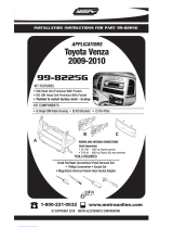
INSTALLATION INSTRUCTIONS FOR PART 99-8223
APPLICATIONS
Toyota Corolla
2009-10
KIT FEATURES
• DIN Radio With Pocket Provision
• ISO Mount Radio with Pocket Provision
• Painted To Match Factory Dash
99-8223= BLACK
99-8223S= SILVER
• A) Radio Housing • B) Radio Housing Trim Plate • C) Radio Housing Brackets
•D) ISO Brackets • E) ISO Trim Plate
KIT COMPONENTS
TOOLS REQUIRED:
Small Flat Blade Screwdriver/ Panel Removal Tool
• Phillips Screwdriver
1-800-221-0932
© COPYRIGHT 2010 METRA ELECTRONICS CORPORATION
www.metraonline.com
A
B
C
99-8223/
99-8223S
D
E
Harness & Antenna Connections (sold separately)
• 70-1761 Toyota Harness 87-up
• TYTO-01 Toyota Amp Interface 03-up

Dash Disassembly
-
Toyota Corolla 2009-10 . . . . . . . . . .
. . . . . . . . . . . . . . . . . . . 1
Kit Assembly
- DIN Radio with Pocket Provision . . . . . . . . . . . . . . . . . . . . . . . . . . . . . 2
- ISO Mount Radio with Pocket Provision . . . . . . . . . . . . . . . . . . . . . . . . 3
Final
Assembly . . . . . . . . . . . . . . . . . . . . . . . . . . . . . . . . . . . . . . . . . . . 4
TABLE OF CONTENTS
99-8223
*Note:
Refer also to the instructions included with the aftermarket radio.
K
NOWLEDGE IS
P
OWER
Enhance your installation and fabrication skills by
enrolling in the most recognized and respected
mobile electronics school in our industry.
Log onto www.installerinstitute.com or call
800-354-6782 for more information and take steps
toward a better tomorrow.

99-8223 DASH DISASSEMBLY
Toyota Corolla 2009-10
1
Disconnect the negative battery ter-
minal to prevent an accidental short
circuit.
1
Unclip and remove the (4) side trim
panels from the right and left side of
the radio and a/c controls. (
Figure A)
2
Unclip and remove the a/c vent panel
above the factory radio.
(Figure B)
3
Remove (4) 10 MM bolts securing the
radio.
(Figure C)
4
Remove (4) plastic clips from the
back of the factory radio. (Retain the
clips for re-use during kit assembly.)
5
Continue to kit assembly.
A
B
C

99-8223 KIT ASSEMBLY
2
A
B
C
D
DIN RADIO WITH POCKET PROVISION
Slide the Radio Housing Brackets onto
the sides of the Radio Housing until the
side clips engage. NO
TE: Tabs are
marked Left and Right.
(Figure B)
2
Slide the DIN cage into the Radio
Housing and secure by bending the
metal locking tabs outward.
(Figure C)
3
Slide the aftermarket radio into the
cage until it snaps into place.
(Figure D)
4
Attach the clips removed from the fac-
tory radio to the back of the radio
housing trim plate.
(Figure A)
1
Continue to final assembly.
*Note: Refer also to the instructions included with the aftermarket radio.

99-8223 KIT ASSEMBLY
3
A
B
C
D
ISO MOUNT RADIO WITH POCKET PROVISION
Slide the Radio Housing Brackets onto
the sides of the Radio Housing until the
side clips engage. NO
TE: Tabs are
marked Left and Right.
(Figure B)
2
Mount the ISO Brackets to the radio
using the screws supplied with the
radio.
(Figure C)
3
Slide the radio into the radio housing
until it snaps into place.
(Figure D)
4
Snap the Trim plate onto the front of
the Radio Housing.
(Figure D)
5
Attach the clips removed from the fac-
tory radio to the back of the radio
housing trim plate.
(Figure A)
1
Continue to final assembly.
*Note: Refer also to the instructions included with the aftermarket radio.

99-8223 FINAL ASSEMBLY
FINAL ASSEMBLY
(A) Strip wire ends back 1/2"
B) Twist ends together
C) Solder
D) Tape
A
B
C
D
Locate the factory wiring harness in the dash. Metra recommends using the
proper mating adapter and making connections as shown. (Isolate and individ-
ually tape off the ends of any unused wires to prevent electrical short circuit.)
Re-connect the negative battery terminal and test the unit for proper operation.
Reassemble in reverse order of disassembly using the 99-8223 Radio Housing
Trim Plate in place of the factory radio trim panel.
1
2
3
FINAL WIRING CONNECTIONS
Make wiring connections using the EIA color code chart shown below and the instructions included with the
head unit. Metra recommends making connections as shown below; Strip, Splice, Solder, Tape. Isolate and
individually tape off ends of any unused wires to prevent electrical short circuit.
METRA / EIA WIRING CODE
12V Ignition / Acc. . . . . . . . . . Red
12V Batt / Memory. . . . . . . . . Yellow
Ground. . . . . . . . . . . . . . . . . . Black*
Power Antenna. . . . . . . . . . . . Blue
Amp Turn-On . . . . . . . . . . . . . Blue / White
Amp Ground. . . . . . . . . . . . . . Black / White
Illumination . . . . . . . . . . . . . . Orange
Dimmer . . . . . . . . . . . . . . . . . Orange / White
Right Front (+) . . . . . . . . . . . . Gray
Right Front (-). . . . . . . . . . . . . Gray/ Black
Left Front (+) . . . . . . . . . . . . . White
Left Front (-). . . . . . . . . . . . . . White / Black
Right Rear (+) . . . . . . . . . . . . Violet
Right Rear (-) . . . . . . . . . . . . . Violet / Black
Left Rear (+) . . . . . . . . . . . . . Green
Left Rear (-) . . . . . . . . . . . . . . Green / Black
*NOTE: When a Black wire is not present, ground radio to vehicle chassis.
All colors may not be present on all leads due to manufacturer’
s specifications.
4

99-8223
NOTES
5

99-8223 INSTRUCTIONS
1-800-221-0932
REV. 04/29/10 © COPYRIGHT 2004-2010 METRA ELECTRONICS CORPORATION INST99-8223
www.metraonline.com
/