Page is loading ...

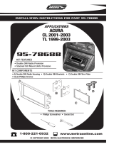
INSTALLATION INSTRUCTIONS FOR PART 95-8204
95-8204
KIT FEATURES
• Double DIN Radio Provision
• Stacked ISO Units Provision
A) Double DIN Trim Plate B) Double DIN Brackets
KIT COMPONENTS
A
Small Flat Blade Screwdriver • Panel Removal Tool
• Phillips Screwdriver • Socket Set
1-800-221-0932
© COPYRIGHT 2004-2007 METRA ELECTRONICS CORPORA
TION
www.metr
aonline.com
TOOLS REQUIRED:
APPLICATIONS
Toyota Corolla
2003-2008
B

Dash Disassembly
- Totota Corolla 2003-2008 ..........................................1
Kit Assembly
- Double DIN Radio Provision .......................................2
- Stacked ISO Units Provision.......................................3
Final
Assembly . . . . . . . . . . . . . . . . . . . . . . . . . . . . . . . . . . . . . . . . . .
4
TABLE OF CONTENTS
95-8204
*Note:
Refer also to the instructions included with the aftermarket radio.

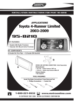
95-8204 DASH DISASSEMBLY
TOYOTA COROLLA 2003-2008
A
B
1
Disconnect the negative battery ter-
minal to prevent an accidental short
circuit.
1
Unclip and remove the gear shifter
trim panel.
(Figure A)
2
Remove the center a/c knob and (1)
Phillips screw exposed behind it.
(Figure B)
3
Unclip and remove the a/c-pocket
assembly.
(Figure C)
4
Remove (4) 10 MM bolts from the bot-
tom of the radio then unclip and
remove the factory radio and trim
panel together. Unplug radio from fac-
tory harness.
(Figure D)
5
Unclip and remove the radio trim
panel including the a/c vents from the
factory radio.
6
Continue to kit assembly.
PASSENGER
A/C
LO
O
FF
HI
C
PASSENGER
A/C
LO
OFF
HI
D
A/C
P
R
N
D
2
L

2
95-8204 KIT ASSEMBLY
B
A
DOUBLE DIN RADIO PROVISION
Slide the Double DIN radio into the
Double DIN brackets and secure the
radio to the brackets using the screws
supplied with the radio.
(Figure B)
2
Continue to final assembly.
*Note: Refer also to the instructions included with the aftermarket radio.
Snap the Double DIN trim plate into the
factory trim panel.
(Figure A)
1

3
95-8204 KIT ASSEMBLY
B
A
STACKED ISO UNITS PROVISION
Slide the stacked ISO units into the
Double DIN brackets and secure the
units to the brackets using the screws
supplied with the units.
(Figure B)
2
Continue to final assembly.
*Note: Refer also to the instructions included with the aftermarket radio.
Snap the Double DIN trim plate into the
factory trim panel.
(Figure A)
1

95-8204 FINAL ASSEMBLY
FINAL ASSEMBLY
(A) Strip wire ends back 1/2"
B) Twist ends together
C) Solder
D) Tape
A
B
C
D
Locate the factory wiring harness in the dash. Metra recommends using the
proper mating adapter and making connections as shown. (Isolate and individ-
ually tape off the ends of any unused wires to prevent electrical short circuit.)
Re-connect the negative battery terminal and test the unit for proper operation.
Reassemble radio and dash assemblies in reverse order of disassembly.
1
2
3
4
FINAL WIRING CONNECTIONS
Make wiring connections using the EIA color code chart shown below and the instructions included with the
head unit. Metra recommends making connections as shown below; Strip, Splice, Solder, Tape. Isolate and
individually tape off ends of any unused wires to prevent electrical short circuit.
METRA / EIA WIRING CODE
12V Ignition / Acc. . . . . . . . . . Red
12V Batt / Memory. . . . . . . . . Yellow
Ground. . . . . . . . . . . . . . . . . . Black*
Power Antenna. . . . . . . . . . . . Blue
Amp Turn-On . . . . . . . . . . . . . Blue / White
Amp Ground. . . . . . . . . . . . . . Black / White
Illumination . . . . . . . . . . . . . . Orange
Dimmer . . . . . . . . . . . . . . . . .
Orange /
White
Right Front (+) . . . . . . . . . . . . Gray
Right Front (-). . . . . . . . . . . . . Gray/ Black
Left Front (+) . . . . . . . . . . . . . White
Left Front (-). . . . . . . . . . . . . . White / Black
Right Rear (+) . . . . . . . . . . . . Violet
Right Rear (-) . . . . . . . . . . . . . Violet / Black
Left Rear (+) . . . . . . . . . . . . . Green
Left Rear (-)
. . . . . . . . . . . . . .
Green / Black
*NOTE: When a Black wire is not present, ground radio to vehicle chassis.
All colors may not be present on all leads due to manufacturer’s specifications.

95-8204
NOTES
5

95-8204 INSTRUCTIONS
1-800-221-0932
REV. 10/02/07 © COPYRIGHT 2004 METRA ELECTRONICS CORPORATION INST95-8204
www.metraonline.com
/