Supermicro SuperServer 7036A-T User manual
- Category
- Server barebones
- Type
- User manual

SUPER
SuperWorkstation 7036A-T
®
USER’S MANUAL
Revision 1.0b

The information in this User’s Manual has been carefully reviewed and is believed to be accurate.
The vendor assumes no responsibility for any inaccuracies that may be contained in this document,
makes no commitment to update or to keep current the information in this manual, or to notify any
person or organization of the updates. Please Note: For the most up-to-date version of this
manual, please see our web site at www.supermicro.com.
Super Micro Computer, Inc. ("Supermicro") reserves the right to make changes to the product
described in this manual at any time and without notice. This product, including software and docu-
mentation, is the property of Supermicro and/or its licensors, and is supplied only under a license.
Any use or reproduction of this product is not allowed, except as expressly permitted by the terms
of said license.
IN NO EVENT WILL SUPERMICRO BE LIABLE FOR DIRECT, INDIRECT, SPECIAL, INCIDENTAL,
SPECULATIVE OR CONSEQUENTIAL DAMAGES ARISING FROM THE USE OR INABILITY TO
USE THIS PRODUCT OR DOCUMENTATION, EVEN IF ADVISED OF THE POSSIBILITY OF
SUCH DAMAGES. IN PARTICULAR, SUPERMICRO SHALL NOT HAVE LIABILITY FOR ANY
HARDWARE, SOFTWARE, OR DATA STORED OR USED WITH THE PRODUCT, INCLUDING THE
COSTS OF REPAIRING, REPLACING, INTEGRATING, INSTALLING OR RECOVERING SUCH
HARDWARE, SOFTWARE, OR DATA.
Any disputes arising between manufacturer and customer shall be governed by the laws of Santa
Clara County in the State of California, USA. The State of California, County of Santa Clara shall
be the exclusive venue for the resolution of any such disputes. Super Micro's total liability for all
claims will not exceed the price paid for the hardware product.
FCC Statement: This equipment has been tested and found to comply with the limits for a Class A
digital device pursuant to Part 15 of the FCC Rules. These limits are designed to provide reasonable
protection against harmful interference when the equipment is operated in a commercial environ-
ment. This equipment generates, uses, and can radiate radio frequency energy and, if not installed
and used in accordance with the manufacturer’s instruction manual, may cause harmful interference
with radio communications. Operation of this equipment in a residential area is likely to cause harmful
interference, in which case you will be required to correct the interference at your own expense.
California Best Management Practices Regulations for Perchlorate Materials: This Perchlorate warn-
ing applies only to products containing CR (Manganese Dioxide) Lithium coin cells. “Perchlorate
Material-special handling may apply. See www.dtsc.ca.gov/hazardouswaste/perchlorate”
WARNING: Handling of lead solder materials used in this
product may expose you to lead, a chemical known to the
State of California to cause birth defects and other repro-
ductive harm.
Manual Revision 1.0b
Release Date: March 14, 2011
Unless you request and receive written permission from Super Micro Computer, Inc., you may not
copy any part of this document.
Information in this document is subject to change without notice. Other products and companies
referred to herein are trademarks or registered trademarks of their respective companies or mark
holders.
Copyright © 2011 by Super Micro Computer, Inc.
All rights reserved.
Printed in the United States of America

Preface
About This Manual
This manual is written for professional system integrators and PC technicians. It
provides information for the installation and use of the SuperWorkstation 7036A-T.
Installation and maintenance shall be performed by experienced technicians only.
The SuperWorkstation 7036A-T is a dual processor system based on the SC733TQ-
665B mid-tower chassis and the Super X8DAL-i serverboard. Please refer to our
web site for an up-to-date list of supported processors.
Manual Organization
Chapter 1: Introduction
The fi rst chapter provides a checklist of the main components included with the
system and describes the main features of the Super X8DAL-i serverboard and
the SC733TQ-665B chassis.
Chapter 2: Installation
This chapter describes the steps necessary to setup the system. If your workstation
was ordered without the processor and memory components, this chapter will refer
you to the appropriate sections of the manual for their installation.
Chapter 3: System Interface
Refer to this chapter for details on the system interface, which includes the functions
and information provided by the control panel on the chassis as well as other LEDs
located throughout the system.
Chapter 4: System Safety
You should thoroughly familiarize yourself with this chapter for a general overview
of safety precautions that should be followed when installing and servicing the
SuperWorkstation 7036A-T.
iii
Preface

iv
Chapter 5: Advanced Serverboard Setup
Chapter 5 provides detailed information on the X8DAL-i serverboard, including the
locations and functions of connectors, headers and jumpers. Refer to this chapter
when adding or removing processors or main memory and when reconfi guring the
serverboard.
Chapter 6: Advanced Chassis Setup
Refer to Chapter 6 for detailed information on the SC733TQ-665B mid-tower chas-
sis. You should follow the procedures given in this chapter when installing, removing
or reconfi guring Serial ATA or peripheral drives and when replacing system power
supply units and cooling fans.
Chapter 7: BIOS
The BIOS chapter includes an introduction to BIOS and provides detailed informa-
tion on running the CMOS Setup Utility.
Appendix A: BIOS POST Messages
Appendix B: BIOS POST Codes
Appendix C: System Specifi cations
SUPERWORKSTATION 7036A-T User's Manual

v
Preface
Notes

vi
Table of Contents
Chapter 1 Introduction
1-1 Overview ......................................................................................................... 1-1
1-2 Serverboard Features ..................................................................................... 1-2
Processors ...................................................................................................... 1-2
Memory ........................................................................................................... 1-2
Serial ATA ....................................................................................................... 1-2
PCI Expansion Slots ....................................................................................... 1-2
I/O Ports .......................................................................................................... 1-2
Other Features ................................................................................................ 1-3
1-3 Chassis Features ............................................................................................ 1-3
System Power ................................................................................................. 1-3
SATA Subsystem ............................................................................................. 1-3
Front Control Panel ......................................................................................... 1-3
Cooling System ............................................................................................... 1-3
1-4 Contacting Supermicro .................................................................................... 1-5
Chapter 2 System Setup
2-1 Overview ......................................................................................................... 2-1
2-2 Unpacking the System .................................................................................... 2-1
2-3 Setting Up the System .................................................................................... 2-2
Checking the Motherboard Setup ................................................................... 2-2
Checking the Drive Bay Setup ........................................................................ 2-2
Chapter 3 System Interface
3-1 Overview ......................................................................................................... 3-1
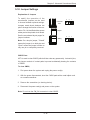
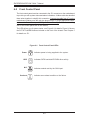
3-2 Control Panel Buttons ..................................................................................... 3-1
RESET ............................................................................................................ 3-1
POWER ........................................................................................................... 3-1
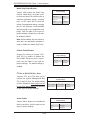
3-3 Control Panel LEDs ........................................................................................ 3-2
Power .............................................................................................................. 3-2
HDD ................................................................................................................. 3-2
NIC .................................................................................................................. 3-2
Overheat/Fan Fail ........................................................................................... 3-2
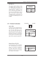
3-4 SATA Drive Carrier LEDs ................................................................................ 3-3
Chapter 4 System Safety
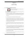
4-1 Electrical Safety Precautions .......................................................................... 4-1
4-2 General Safety Precautions ............................................................................ 4-2
4-3 ESD Precautions ............................................................................................. 4-3
SUPERWORKSTATION 7036A-T User's Manual

vii
Table of Contents
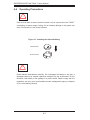
4-4 Operating Precautions .................................................................................... 4-4
Chapter 5 Advanced Serverboard Setup
5-1 Handling the Serverboard ............................................................................... 5-1
Precautions ..................................................................................................... 5-1
Unpacking ....................................................................................................... 5-2
5-2 Serverboard Installation .................................................................................. 5-2
5-3 Connecting Cables .......................................................................................... 5-3
Connecting Data Cables ................................................................................. 5-3
Connecting Power Cables .............................................................................. 5-3
Connecting the Control Panel ......................................................................... 5-3
5-4 I/O Ports .......................................................................................................... 5-4
5-5 Installing a Processor and Heatsink ............................................................... 5-5
Installing an LGA1366 Processor ................................................................... 5-5
Installing a CPU Heatsink ............................................................................... 5-7
5-6 Installing Memory ............................................................................................ 5-8
Memory Support .............................................................................................. 5-8
DIMM Installation ............................................................................................ 5-8
Populating DIMMs ...................................................................................... 5-9
5-7 Installing PCI Expansion Cards .................................................................... 5-10
5-8 Serverboard Details .......................................................................................5-11
X8DAL-i Quick Reference ............................................................................. 5-12
5-9 Connector Defi nitions ................................................................................... 5-13
Main ATX Power Supply Connector ......................................................... 5-13
Secondary Power Connectors.................................................................. 5-13
Power Button ............................................................................................ 5-13
Reset Button ............................................................................................. 5-13
Power Fail LED ....................................................................................... 5-13
Overheat/Fan Fail LED (OH).................................................................... 5-14
NIC2 (JLAN2) LED ................................................................................... 5-14
NIC1 (JLAN1) LED ................................................................................... 5-14
HDD LED .................................................................................................. 5-14
Power On LED ......................................................................................... 5-14
NMI Button ............................................................................................... 5-15
Fan Headers ............................................................................................. 5-15
ATX PS/2 Keyboard and PS/2 Mouse Ports ............................................ 5-15
Chassis Intrusion ...................................................................................... 5-15
Serial Ports ............................................................................................... 5-16
Power LED/Speaker ................................................................................. 5-16
Universal Serial Bus (USB) ...................................................................... 5-16

viii
LAN1/2 (Ethernet Ports) .......................................................................... 5-16
SGPIO Headers ....................................................................................... 5-17
Power I
2
C Connector ................................................................................ 5-17
Overheat LED/Fan Fail (JOH1) ................................................................ 5-17
CD Header ............................................................................................... 5-17
Front Panel Audio ..................................................................................... 5-18
High Defi nition Audio (HD Audio) ............................................................ 5-18
5-10 Jumper Settings ............................................................................................ 5-19
Explanation of Jumpers ............................................................................ 5-19
CMOS Clear ............................................................................................. 5-19
Watch Dog Enable/Disable ...................................................................... 5-20
LAN1/2 Enable/Disable ........................................................................... 5-20
I
2
C Bus to PCI-X/PCI-Exp. Slots .............................................................. 5-20
Audio Enable ............................................................................................ 5-20
USB Wake-Up .......................................................................................... 5-21
5-11 Onboard Indicators ........................................................................................ 5-21
LAN1/2 LEDs ............................................................................................ 5-21
Onboard Power LED (LE1) ...................................................................... 5-21
5-12 SATA Ports .................................................................................................... 5-22
SATA Ports ............................................................................................... 5-22
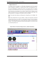
5-13 Installing Software ......................................................................................... 5-23
Supero Doctor III ........................................................................................... 5-24
Chapter 6 Advanced Chassis Setup
6-1 Static-Sensitive Devices .................................................................................. 6-1
Precautions ..................................................................................................... 6-1
Unpacking ....................................................................................................... 6-1
6-2 Front Control Panel ......................................................................................... 6-2
6-3 System Fans ................................................................................................... 6-4
Fan Failure ...................................................................................................... 6-4
Replacing System Fans ............................................................................. 6-4
Identifying and accessing the fan .............................................................. 6-4
Removing the fan duct assembly ............................................................... 6-4
Installing a new fan .................................................................................... 6-5
6-4 Drive Bay Installation ...................................................................................... 6-6
Serial ATA Drives ............................................................................................. 6-6
Removing SATA drives ............................................................................... 6-6
Mounting a SATA drive in a drive carrier ................................................... 6-6
SUPERWORKSTATION 7036A-T User's Manual

Installing Components in the 5.25" Drive Bays .............................................. 6-8
6-5 Power Supply .................................................................................................. 6-9
Chapter 7 BIOS
7-1 Introduction ...................................................................................................... 7-1
Starting BIOS Setup Utility .............................................................................. 7-1
How To Change the Confi guration Data ......................................................... 7-1
Starting the Setup Utility ................................................................................. 7-2
7-2 Main Setup ...................................................................................................... 7-2
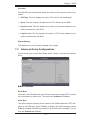
7-3 Advanced Setup Confi gurations...................................................................... 7-3
7-4 Security Settings ........................................................................................... 7-20
7-5 Boot Confi guration ........................................................................................ 7-21
7-6 Exit Options ................................................................................................... 7-23
Appendix A BIOS Error Beep Codes
Appendix B Installing Windows
Appendix C System Specifi cations
ix
Table of Contents

Notes
x
SUPERWORKSTATION 7036A-T User's Manual

Chapter 1
Introduction
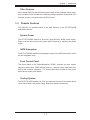
1-1 Overview
The SuperWorkstation 7036A-T is a high-end workstation comprised of two main
subsystems: the SC733TQ-665B mid-tower chassis and the X8DAL-i serverboard.
Please refer to our web site for information on operating systems that have been
certifi ed for use with the SuperWorkstation 7036A-T (www.supermicro.com).
In addition to the serverboard and chassis, various hardware components have
been included with the SuperWorkstation 7036A-T, as listed below:
One 9-cm cooling fan (FAN-0076L4)
•
One 12-cm cooling fan (FAN-0077L4)•
Two passive CPU heatsinks (SNK-P0035AP4)•
One I/O backplate (MCP-260-00001-00)•
SATA Accessories •
One SATA backplane (CSE-SAS-733TQ)
Four 48-cm SATA cables (CBL-0178L)
Four SATA drive carriers (CSE-PT39-B)
One SGPIO cable (CBL-0157L)
One SuperWorkstation 7036A-T User's Manual
•
Chapter 1: Introduction
1-1

1-2
SUPERWORKSTATION 7036A-T User's Manual
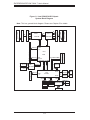
1-2 Serverboard Features
At the heart of the SuperWorkstation 7036A-T lies the X8DAL-i, a dual processor
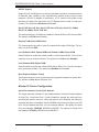
serverboard based on the Intel® 5500 chipset. Below are the main features of the
X8DAL-i. (See Figure 1-1 for a block diagram of the chipset).
Processors
The X8DAL-i supports two Intel 5500 Series (LGA 1366) processors. Please refer
to the serverboard description pages on our web site for a complete listing of sup-
ported processors (www.supermicro.com).
Memory
The X8DAL-i has six 240-pin DIMM slots that can support up to 48 GB of regis-
tered ECC DDR3-1333/1066/800 or up to 24 GB of unbuffered non-ECC DDR3-
1333/1066/800 memory. Modules of the same size and speed are recommended
for use. See Chapter 5 for details.
Serial ATA
A SATA controller is integrated into the South Bridge (ICH10R) section of the
chipset to provide a six-port, 3 Gb/s SATA subsystem, which is RAID 0, 1, 10
and 5 capable (RAID 0, 1 and 10 supported with Linux). The SATA drives are
hot-swappable units.
Note: The operating system you use must have RAID support to enable the hot-
swap capability and RAID function of the Serial ATA drives. For more information
on the SATA HostRAID confi guration, please refer to the Intel SATA HostRAID User's
Guide posted on our website: http://www.supermicro.com/support/manuals/.
PCI Expansion Slots
The X8DAL-i has one PCI-Express 2.0 x16 slot, one PCI-Express 2.0 x4 slot, one
PCI-Express x4 slot and two 32-bit PCI slots.
I/O Ports
The color-coded I/O ports include one COM ports, four USB 2.0 ports, PS/2 mouse
and keyboard ports, two LAN (Gb Ethernet) ports and six HDA (High Defi nition
Audio) ports.

1-3
Chapter 1: Introduction
Other Features
Other onboard features that promote system health include onboard voltage moni-
tors, a chassis intrusion header, auto-switching voltage regulators, chassis and CPU
overheat sensors, virus protection and BIOS rescue.
1-3 Chassis Features
The following is a general outline of the main features of the SC733TQ-665B
workstation chassis.
System Power
The SC733TQ-665B features a low-noise, high-effi ciency 665W power supply.
Power must be removed from the system before servicing or replacing the power
supply.
SATA Subsystem
The SC733TQ-665B chassis was designed to support four SATA hard drives, which
are hot-swappable units.
Front Control Panel
The control panel on the SuperWorkstation 7036A-T provides you with system
monitoring and control. LEDs indicate power on, network activity, hard disk drive
activity and overheat conditions. The control panel also includes a main power
button and a system reset button.
Cooling System
The SC733TQ-665B chassis one 9-cm fan located at the front of the chassis and a
12-cm fan located in the power supply. Both fans operate continuously.

1-4
SUPERWORKSTATION 7036A-T User's Manual
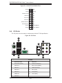
Figure 1-1. Intel 5500/ICH10R Chipset:
System Block Diagram
Note: This is a general block diagram. Please see Chapter 5 for details.
82574L
PCI-Ex8 Slot3
RJ45
x1
x4
Intel
82574L
RJ45
x1
DDR3 DIMM
E
F
C
A
B
D
E
F
3
LSI 1068E
Ports
4~7
Ports
0~3
SATA 2
SATA 3
SATA 4
SATA 5
SATA 6
ESI
SATA 1
SATA
SIO
W83627DHG
LPC
PS2 KB/MS
SPI
SST
25VF016
CLINK
CLINK
Ports
1~4
x4
x16
ICH10R
DMI
5500
Port 0
Ports
Ports
1,2
7,8,9,10
Port
CSI
Port 5
Port 6
DDR3 DIMM
DDR3 DIMM
DDR3 DIMM
DDR3 DIMM
DDR3 DIMM
B
C
COM1
COM2
USB 0/1
USB
USB 2/3
USB 4/5
USB 6
PCI-E x16 Slot6
PCI-E x16 Slot5
PCI32/33 Slot1
PCI32/33 Slot2
PCI
PCI32bit/33MHz
Gen2
Gen2
Gen1
Gen2
B3
Port 1
x4
Intel
Intel
Intel
LGA1366
LGA1366
CPU 1
CPU 2
SAS
SAS
SAS CTRL

1-5
Chapter 1: Introduction
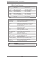
1-4 Contacting Supermicro
Headquarters
Address: Super Micro Computer, Inc.
980 Rock Ave.
San Jose, CA 95131 U.S.A.
Tel: +1 (408) 503-8000
Fax: +1 (408) 503-8008
Email: [email protected] (General Information)
[email protected] (Technical Support)
Web Site: www.supermicro.com
Europe
Address: Super Micro Computer B.V.
Het Sterrenbeeld 28, 5215 ML
's-Hertogenbosch, The Netherlands
Tel: +31 (0) 73-6400390
Fax: +31 (0) 73-6416525
Email: [email protected] (General Information)
[email protected] (Technical Support)
[email protected] (Customer Support)
Asia-Pacifi c
Address: Super Micro Computer, Inc.
4F, No. 232-1, Liancheng Rd.
Chung-Ho 235, Taipei County
Taiwan, R.O.C.
Tel: +886-(2) 8226-3990
Fax: +886-(2) 8226-3991
Web Site: www.supermicro.com.tw
Technical Support:
Email: [email protected]
Tel: 886-2-8228-1366, ext.132 or 139

1-6
SUPERWORKSTATION 7036A-T User's Manual
Notes

Chapter 2: System Setup
2-1
Chapter 2
System Setup
2-1 Overview
This chapter provides a quick setup checklist to get your SuperWorkstation 7036A-T
up and running. Following the steps in the order given should enable you to have
the system operational within a minimal amount of time. If your system is not al-
ready fully integrated with a motherboard, processor, system memory etc., please
turn to the chapter or section noted in each step for details on installing specifi c
components.
2-2 Unpacking the System
You should inspect the box the SuperWorkstation 7036A-T was shipped in and note
if it was damaged in any way. If the workstation itself shows damage, you should
fi le a damage claim with the carrier who delivered it.
Decide on a suitable location for setting up and operating the SuperWorkstation
7036A-T. It should be situated in a clean, dust-free area that is well ventilated. Avoid
areas where heat, electrical noise and electromagnetic fi elds are generated. You
will also need it placed near a grounded power outlet.
Once the SuperWorkstation 7036A-T is placed in the appropriate location, slide the
locking tabs on each caster down to keep it stationary.
!
!
Warnings and Precautions!
Ensure that the caster wheels on the workstation are locked.•
Review the electrical and general safety precautions in Chapter 4.•
Use a regulating uninterruptible power supply (UPS) to protect the workstation •
from power surges, voltage spikes and to keep your system operating in case
of a power failure.
Allow the power supply units and hot-swap SATA drives to cool before touch-
•
ing them.

2-2
SUPERWORKSTATION 7036A-T User's Manual
To maintain proper cooling, always keep all chassis panels closed and all SATA •
carriers installed when not being serviced.
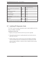
2-3 Setting Up the System
You should fi rst open the left side panel (when facing the front of the chassis)
to make sure the motherboard is properly installed and all connections have been
made.
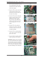
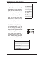
Checking the Motherboard Setup
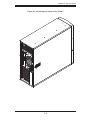
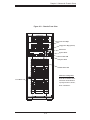
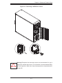
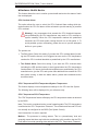
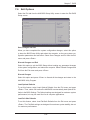
Accessing the inside of the system (Figure 2-1): Begin by removing the two 1.
screws from the back lip of the side cover (this is the left cover when looking
at the chassis from the front.) Grab the handle and gently pull the side cover
out to release it from its position. Once the side cover is out of its position,
slide the cover out of the chassis.
Check the CPU (processor): You may have one processor already installed 2.
into the system board. The processor should have its own heatsink attached.
See Chapter 5 for instructions on processor installation.
Check the system memory:3. Your system may have come with system
memory already installed. Make sure all DIMMs are fully seated in their slots.
For details on adding system memory, refer to Chapter 5.
Installing add-on cards:4. If desired, you can install up to seven add-on cards
to the system. See Chapter 5 for details on installing PCI-E/PCI-X/PCI add-on
cards.
Check all cable connections and airfl ow: Make sure all power and data cables 5.
are properly connected and not blocking the airfl ow. See Chapter 5 for details
on cable connections.
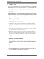
Checking the Drive Bay Setup
Next, you should check to make sure the peripheral drives and the SATA drives
and SATA backplane have been properly installed and all essential connections
have been made.
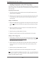
Accessing the peripheral drive bays: To install or remove a component in the 1.
3.5" and/or 5.25" drive bay(s), you will need to remove the side chassis cover.

Chapter 2: System Setup
2-3
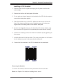
Figure 2-1. Accessing the Inside of the 7036A-T

2-4
SUPERWORKSTATION 7036A-T User's Manual
See the installation and removal sections for the peripheral drives in Chapter
6.
Check the SATA disk drives: Depending upon your system's confi guration, 2.
your system may have up to four SATA drives already installed. If you need
to install or remove an SATA drive, please refer to the appropriate section in
Chapter 6.
Check the airfl ow: Cooling air is provided by a 9-cm internal cooling fan and a 3.
12-cm fan. The system component layout was carefully designed to promote
suffi cient airfl ow throughout the chassis. Also note that all power and data
cables have been routed in such a way that they do not block the airfl ow
generated by the fan. Please keep this in mind when rerouting or adding/
removing cables.
Supplying power to the system: The last thing you must do is to provide input 4.
power to the system. Plug the power cord from the power supply unit into a
high-quality power strip that offers protection from electrical noise and power
surges. It is recommended that you use an uninterruptible power supply
(UPS).
Page is loading ...
Page is loading ...
Page is loading ...
Page is loading ...
Page is loading ...
Page is loading ...
Page is loading ...
Page is loading ...
Page is loading ...
Page is loading ...
Page is loading ...
Page is loading ...
Page is loading ...
Page is loading ...
Page is loading ...
Page is loading ...
Page is loading ...
Page is loading ...
Page is loading ...
Page is loading ...
Page is loading ...
Page is loading ...
Page is loading ...
Page is loading ...
Page is loading ...
Page is loading ...
Page is loading ...
Page is loading ...
Page is loading ...
Page is loading ...
Page is loading ...
Page is loading ...
Page is loading ...
Page is loading ...
Page is loading ...
Page is loading ...
Page is loading ...
Page is loading ...
Page is loading ...
Page is loading ...
Page is loading ...
Page is loading ...
Page is loading ...
Page is loading ...
Page is loading ...
Page is loading ...
Page is loading ...
Page is loading ...
Page is loading ...
Page is loading ...
Page is loading ...
Page is loading ...
Page is loading ...
Page is loading ...
Page is loading ...
Page is loading ...
Page is loading ...
Page is loading ...
Page is loading ...
Page is loading ...
Page is loading ...
Page is loading ...
Page is loading ...
Page is loading ...
Page is loading ...
Page is loading ...
Page is loading ...
Page is loading ...
Page is loading ...
Page is loading ...
Page is loading ...
Page is loading ...
Page is loading ...
Page is loading ...
Page is loading ...
Page is loading ...
-
 1
1
-
 2
2
-
 3
3
-
 4
4
-
 5
5
-
 6
6
-
 7
7
-
 8
8
-
 9
9
-
 10
10
-
 11
11
-
 12
12
-
 13
13
-
 14
14
-
 15
15
-
 16
16
-
 17
17
-
 18
18
-
 19
19
-
 20
20
-
 21
21
-
 22
22
-
 23
23
-
 24
24
-
 25
25
-
 26
26
-
 27
27
-
 28
28
-
 29
29
-
 30
30
-
 31
31
-
 32
32
-
 33
33
-
 34
34
-
 35
35
-
 36
36
-
 37
37
-
 38
38
-
 39
39
-
 40
40
-
 41
41
-
 42
42
-
 43
43
-
 44
44
-
 45
45
-
 46
46
-
 47
47
-
 48
48
-
 49
49
-
 50
50
-
 51
51
-
 52
52
-
 53
53
-
 54
54
-
 55
55
-
 56
56
-
 57
57
-
 58
58
-
 59
59
-
 60
60
-
 61
61
-
 62
62
-
 63
63
-
 64
64
-
 65
65
-
 66
66
-
 67
67
-
 68
68
-
 69
69
-
 70
70
-
 71
71
-
 72
72
-
 73
73
-
 74
74
-
 75
75
-
 76
76
-
 77
77
-
 78
78
-
 79
79
-
 80
80
-
 81
81
-
 82
82
-
 83
83
-
 84
84
-
 85
85
-
 86
86
-
 87
87
-
 88
88
-
 89
89
-
 90
90
-
 91
91
-
 92
92
-
 93
93
-
 94
94
-
 95
95
-
 96
96


Supermicro SuperServer 7036A-T User manual
- Category
- Server barebones
- Type
- User manual
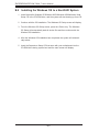
Ask a question and I''ll find the answer in the document
Finding information in a document is now easier with AI
Related papers
-
Supermicro X8DAL-3 User manual
-
Supermicro C7SIM-Q User manual
-
Supermicro MBD-C7SIM-Q-B User manual
-
-
-
-
-
-
-
Other documents
-
 Casetek CK-1028-2B/W Datasheet
-
 Supero C7SIM-Q User manual
-
 Supero SuperWorkstation 5035G-T User manual
-
Sun Microsystems 1500 User manual
-
Acer Altos T110 F4 User manual
-
 Phobya Touch 6 Installating And Operation Manual
-
 Systium Technologies 526EX Assembly Manual
-
MB QUART JC1-108 User manual
-
Sharkoon 4044951007288 Datasheet
-
Intel TM700 User manual


