Description, Specications, and
Installation Manual
25500171
Rev. A3 0423
Printed in U.S.A.
© Copyright 2017-2023 Federal Signal Corporation
Directional Speaker Array
Models: DSA2, DSA4, DSA6

Limited Warranty
This product is subject to and covered by a limited warranty,
a copy of which can be found at www.fedsig.com/SSG-Warranty.
A copy of this limited warranty can also be obtained by written
request to Federal Signal Corporation, 2645 Federal Signal Drive,
University Park, IL 60484, email to [email protected] or
call +1 708-534-3400.
This limited warranty is in lieu of all other warranties, express or
implied, contractual or statutory, including, but not limited to the
warranty of merchantability, warranty of tness for a particular
purpose and any warranty against failure of its essential purpose.
All product names or trademarks are properties of their respective owners.
2645 Federal Signal Drive
University Park, Illinois 60484
www.fedsig.com
Customer Support 800-548-7229 • +1 708 534-3400
Technical Support 800-524-3021 • +1 708 534-3400

3
Description, Specications, and Installation Manual
Federal Signal www.fedsig.com
Contents
Safety Messages......................................................................................................................................................5
General Description ................................................................................................................................................7
Introduction ........................................................................................................................................................7
Features .............................................................................................................................................................. 8
Specications ..........................................................................................................................................................8
Wiring Options ....................................................................................................................................................... 10
Installation Instructions ........................................................................................................................................ 11
Determine a Suitable Location .......................................................................................................................... 11
Installing the Sirens ...........................................................................................................................................12
Installation Bracket Options ......................................................................................................................13
Pole Installation .........................................................................................................................................17
Wood Utility Pole Installation ....................................................................................................................18
Concrete or Metal Pole Installation ........................................................................................................... 18
Wall Mount Applications ............................................................................................................................ 22
Getting Service ......................................................................................................................................................24
Appendix A DSA Drawings ...................................................................................................................................25
Tables
Table 1 DSA Specications.....................................................................................................................................8
Table 2 Mounting Congurations and Horizontal Coverage ...............................................................................8
Table 3 General Specications ...............................................................................................................................9
Table 4 Wind Loading ..............................................................................................................................................9
Table 5 Mounting Kits .............................................................................................................................................9
Table 6 Bracket Options ........................................................................................................................................13
Table 7 Bracket Options for Size of Pole .............................................................................................................18
Table 8 Replacement Parts ...................................................................................................................................24

4
Directional Speaker Array (Models DSA2, DSA4, and DSA6)
Federal Signal www.fedsig.com
Figures
Figure 1 Two DSA4s with a DSAMK4 bracket ....................................................................................................... 7
Figure 2 Various DSA Congurations .................................................................................................................10
Figure 3 Top of pole mount using DSAMK4 ........................................................................................................14
Figure 4 Large Pole Mount ...................................................................................................................................14
Figure 5 Bracket I-IP100-PMW Bracket Picture ..................................................................................................15
Figure 6 Bracket I-IP100-PMW Drawing..............................................................................................................15
Figure 7 Bracket I-IP100-PM Picture .................................................................................................................... 16
Figure 8 Bracket I-IP100-PM Drawing .................................................................................................................. 16
Figure 9 Typical Pole Installation ......................................................................................................................... 17
Figure 10 DSAMK1 Bracket Dimensions .............................................................................................................19
Figure 11 DSAMK1 Bracket Picture .....................................................................................................................19
Figure 12 DSAMKSPB45 Bracket Dimensions ...................................................................................................20
Figure 13 DSAMKSPB45 Bracket Picture............................................................................................................20
Figure 14 DSAMKSPB23 Bracket Dimensions ...................................................................................................21
Figure 15 Top view of DSAMK4 bolt hole pattern ...............................................................................................21
Figure 16 Wall Mount Conguration .................................................................................................................... 22
Figure 17 DSAMKSP Mounting Kit .......................................................................................................................23
Figure 18 DSA Assembly Drawing .......................................................................................................................25
Figure 19 Wiring Options ...................................................................................................................................... 26
Figure 20 Wiring Options Continued ...................................................................................................................27

5
Safety Messages
Description, Specications, and Installation Manual
Federal Signal www.fedsig.com
Safety Messages
It is important to follow all instructions shipped with this product. This device is to be
installed by trained personnel who are thoroughly familiar with the country electric codes
and will follow these guidelines as well as local codes and ordinances, including any state
or local-noise control ordinances.
Listed below are important safety instructions and precautions you should follow:
Important Notice
Federal Signal reserves the right to make changes to devices and specifications
detailed in the manual at any time in order to improve reliability, function or design. The
information in this manual has been carefully checked and is believed to be accurate;
however, no responsibility is assumed for any inaccuracies.
Publications
Federal Signal recommends the following publications from the Federal Emergency
Management Agency for assistance with planning an outdoor warning system:
• The “Outdoor Warning Guide” (CPG 1-17)
• “Civil Preparedness, Principles of Warning” (CPG 1-14)
• FEMA-REP-1, Appendix 3 (Nuclear Plant Guideline)
• FEMA-REP-10 (Nuclear Plant Guideline).
Planning
• If suitable warning equipment is not selected, the installation site for the siren is
not selected properly or the siren is not installed properly, it may not produce the
intended optimum audible warning. Follow Federal Emergency Management Agency
(FEMA) recommendations.
• If sirens are not activated in a timely manner when an emergency condition
exists, they cannot provide the intended audible warning. It is imperative that
knowledgeable people, who are provided with the necessary information, be
available at all times to authorize activation.
• When sirens are used out of doors, people indoors may not be able to hear the
warning signals. Separate warning devices or procedures may be needed to warn
people indoors eectively.
• The sound output of sirens is capable of causing permanent hearing damage. To
prevent excessive exposure, carefully plan siren placement, post warnings, and
restrict access to areas near sirens. Review and comply with any local or state noise
control ordinances as well as OSHA noise exposure regulations and guidelines.
• Activating the sirens may not result in people taking the desired actions if those to
be warned are not properly trained about the meaning of siren sounds. Siren users
should follow FEMA recommendations and instruct those to be warned of corrective
actions to be taken.

6
Safety Messages
Directional Speaker Array (Models DSA2, DSA4, and DSA6)
Federal Signal www.fedsig.com
• After installation, service, or maintenance, test the siren system to confirm that it is
operating properly. Test the system regularly to confirm that it will be operational in
an emergency.
• If future service and operating personnel do not have these instructions to refer
to, the siren system may not provide the intended audible warning and service
personnel may be exposed to death, permanent hearing loss, or other bodily injury.
File these instructions in a safe place and refer to them periodically. Give a copy of
these instructions to new recruits and trainees. Also give a copy to anyone who is
going to service or repair the siren.
Installation and Service
• Electrocution or severe personal injury can occur when performing various
installation and service functions such as making electrical connections, drilling
holes, or lifting equipment. Therefore, only experienced electricians should install
this product in accordance with national, state and any other electrical codes having
jurisdiction. Perform all work under the direction of the installation or service crew
safety foreman.
• The sound output of sirens is capable of causing permanent hearing damage. To
prevent excessive exposure, carefully plan siren placement, post warnings, and
restrict access to areas near the sirens. Sirens may be operated from remote control
points. Whenever possible, disconnect all siren power, including batteries, before
working near the siren. Review and comply with any local or state noise control
ordinances as well as OSHA noise exposure regulations and guidelines.
• After installation or service, test the siren system to confirm that it is operating
properly. Test the system regularly to confirm that it will be operational in an
emergency.
• If future service personnel do not have these warnings and all other instructions
shipped with the equipment to refer to, the siren system may not provide the
intended audible warning and service personnel may be exposed to death,
permanent hearing loss, or other bodily injury. File these instructions in a safe place
and refer to them periodically. Give a copy of these instructions to new recruits and
trainees. Also give a copy to anyone who is going to service or repair the sirens.
Operation
Failure to understand the capabilities and limitations of your siren system could result
in permanent hearing loss, other serious injuries, or death to persons too close to
the sirens when you activate them or to those you need to warn. Carefully read and
thoroughly understand all safety notices in this manual and all operations-related items in
all instruction manuals shipped with the equipment. Thoroughly discuss all contingency
plans with those responsible for warning people in your community, company, or
jurisdiction.
Read and understand the information contained in this manual before attempting
to install or service the siren.
Pay careful attention to notices located on the equipment.

7
General Description
Description, Specications, and Installation Manual
Federal Signal www.fedsig.com
General Description
Introduction
This manual describes the features, specifications, and installation of the Directional
Speaker Array (DSA). See the UltraVoice Electronic Siren Controller Manual for operating
instructions.
The DSA is a flexible and adaptable high-powered speaker array. It can be configured
in many ways to customize your site’s needs. Let Federal Signal design your DSA
configuration. Contact Federal Signal through pre-sales or contact your local sales
representative.
The DSA is a flexible family of high-powered speakers capable of providing audible
signals (tone or voice) over a large area to satisfy varying signaling needs in multiple
directions. A typical installation consists of between one and four arrays designed to be
powered by a Federal Signal UltraVoice Controller. A highly ecient design enables the
speakers to produce a high sound level while making moderate demands on the power
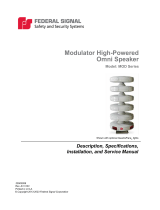
source. Each array can contain between two and six individual speakers. (Figure 1 shows
two DSA4s with a DSAMK4 bracket.)
Figure 1 Two DSA4s with a DSAMK4 bracket
DSA speakers are comprised of fiberglass projectors and aluminum housings and
stainless steel mounting brackets that include hardware for mounting the bracket to the
speaker. Each speaker provides 100 watts of signaling power.
Each DSA2, DSA4, and DSA6 speaker array includes one DSAMK1 bracket. A DSA
speaker requires two brackets for proper mounting. When mounting DSAs to poles,
several brackets can be attached. These brackets provide secure mounting for a variety
of applications. If mounting to a pole, see “Table 6 Bracket Options” on page 13.

8
Specications
Directional Speaker Array (Models DSA2, DSA4, and DSA6)
Federal Signal www.fedsig.com
Each array set covers one 90° quadrant. The dB(C) ratings at 100 feet on axis are shown
below:
DSA2 111 dB(C)
DSA4 117 dB(C)
DSA6 121 dB(C)
The DSA provides excellent voice reproduction and, with the aid of the UltraVoice
Controller, produces the following pre-programmed warning signals: Wail, Pulsed Steady,
Pulsed Wail, Alternating Alert, Alternating Wail, and Westminster Chimes. The UltraVoice
Controller can be networked and provide voice messages for clear instructions during
emergency notifications.
Features
The DSA has the following features:
• Maintenance Free
• Multiple mounting options available—wall, pole (wood or steel)
• Able to mount up to four speaker arrays per pole
• Each speaker contains multiple 100-watt drivers
• Provides excellent voice reproduction when used with the UltraVoice Controller
• Available in three models for a wide range of sound coverage
Specications
Table 1 DSA Specications
Color Black projectors and off-white housing
Paint type TGIC polyester powder coat
Projector Type Re-entrant
Frequency Response 200 to 2000 Hz
Operating temp range -22°F to +140°F (-30°C to +60°C)
Humidity range 95% ± 2%
Table 2 Mounting Congurations and Horizontal Coverage
Single Unit 70°
Two Units:
Side by Side at 90° 180°
Opposite Sides of pole at 180° 140° Collectively
Three adjacent sides at 90° to one another 210°
Four sides at 90° to one another 360°

9
Specications
Description, Specications, and Installation Manual
Federal Signal www.fedsig.com
Table 3 General Specications
Specications DSA2 DSA2-1 DSA4 DSA4-1 DSA6 DSA6-1
Number of
Speakers
2 4 6
Watts 200 400 600
Sound output
per individual
stack, dB(C) at
100 feet
111 117 121
Effective Range
at 70 dB(C)
1700 ft 2600 ft 3400 ft
Height in inches 24.25 48.75 73.25
Net Weight (lb) 43 95 125
Cable Length 45 ft 94 ft 45 ft 94 ft 45 ft 94 ft
Power
Requirements
One UV400 Amplier
Can support two DSA2s
One UV400 Amplier Two UV400 Ampliers
Three UV400s can
support two DSA6s
Table 4 Wind Loading
DSA2 DSA4 DSA6
EPA at 40 feet 3.66 ft27.32 ft210.98 ft2
Wind Load (110 mph, 40 feet above ground) 189 lbf 404 lbf 626 lbf
NOTE: When calculating total power requirements, determine the total number of
speakers needed in your installation, and divide the total by four. The result is the number
of amplifiers required for your installation. If the result is not a whole number, then round
up to the next whole number.
For example, if your site needs 1200 watts, then this is 12 speakers because each speaker
provides 100 watts of signaling power.
Consider the following example:
(12 speakers)/4 = 3 amplifiers.
This example shows that the power requirements are three 400-watt amplifiers.
Table 5 Mounting Kits
DSAMK1 Each DSA is shipped with one DSAMK1 bracket for wall mount
applications. Order an additional DSAMK1 per DSA. See Figure 10.
DSAMK4 Mounting kit for one to four vertical stack(s) 90º apart.
DSAMKSP Mounting kit for the top of steel poles that includes a 4.5-inch pole and
brackets for one DSA.
DSAMKSPB45 Mounting kit for 4.5-inch steel pole. Includes two brackets, two u-bolts,
and mounting hardware for one DSA2, DSA4, or DSA6 speaker. Federal
Signal recommends using two I-IP100-PMW brackets. See Figure 6.
DSAMKSPB23 Mounting kit for 2.375-inch steel pole. Includes two brackets, two u-bolts,
and mounting hardware for one DSA2, DSA4, or DSA6 speaker. Federal
Signal recommends using two I-IP100-PM brackets. See Figure 8.

10
Wiring Options
Directional Speaker Array (Models DSA2, DSA4, and DSA6)
Federal Signal www.fedsig.com
Figure 2 Various DSA Congurations
Wiring Options
You can configure DSA speakers to address many dierent applications when used with
UV Controllers. Typical installations involve one to four DSA speakers operated from a
UV Controller. Equip the UV Controller with up to eight UV400 amplifiers. Each UV400
amplifier provides 400 watts. Also, each DSA is equipped with a four-conductor cable
45feet or 94 feet in length. When installing DSA speakers with fewer than six speakers,
tie o the unused connectors. Do not trim connectors. Use extra connectors, later, to add
accessories or other speakers.
DSA2 Wiring Options
A DSA2 speaker requires 200 watts of power, which uses 50% of a single UV400
amplifier. Use a single UV400 amplifier to power two DSA2s that are wired in parallel for
a total power of 400 watts. A UV Controller equipped with eight UV400 amplifiers can
power up to sixteen DSA2s. See “Figure 19 Wiring Options.”
DSA4 Wiring Options
A DSA4 speaker requires 400 watts of power or a single UV400 amplifier. A UV Controller
equipped with eight UV400 amplifiers can power up to eight DSA4s. See “Figure 19
Wiring Options.”

11
Installation Instructions
Description, Specications, and Installation Manual
Federal Signal www.fedsig.com
DSA6 Wiring Options
A DSA6 speaker requires 600 W of power or two UV400 amplifiers, with one at 100% and
the other at 50%. Equip a UV Controller with six UV400 amplifiers to power fourDSA6s.
Use the remaining two UV400 amplifiers for two DSA4s or other combinations up to
800watts. See “Figure 20 Wiring Options Continued.”
Mixing DSA Speakers Wiring Options
DSA4 speakers always use a single UV400 amplifier. You can mix DSA2 and DSA6 to use
the UV400 amplifiers eciently. When wiring dierent DSA speakers together, be careful
to follow the wiring diagrams to ensure drivers are always in series or series/parallel
arrangement. See Figures 19 and 20 for wiring examples.
Installation Instructions
Determine a Suitable Location
The information in this section provides guidelines to aid you in selecting installation sites
that make the best possible use of the speaker array siren.
SOUND HAZARD: The sound output level of some DSA sirens is capable of
causing permanent hearing damage. To prevent excessive exposure, carefully
plan the placement of the sirens and post warnings.
Do not expose personnel to sound levels above 123 dBC.
When the sirens are used out of doors, people indoors may not be able to hear the
warning signals. You may need separate warning devices or procedures to warn
people indoors effectively.
Careful consideration of the factors aecting the propagation of sound from the siren and
the response of the human ear to the sound will optimize the ability of the siren to warn
the community eectively.
The reduction of signal intensity as distance from the siren increases and the minimum
desired signal level at the fringe of the area to be covered are important considerations
when choosing a siren installation site. As the distance from the siren increases, sound
level losses accumulate. These losses result from weather conditions, the terrain,
obstructions in the sound path, the pitch of the sound, and the height of the siren.
Optimum sound propagation conditions occur when no obstructions exist in the sound
path, the terrain is hard and flat, and the air is blowing away from the source. Under these
conditions, you can expect a 6 dB loss per distance doubled. A loss per distance doubled
of 10 dB is typically experienced because the atmosphere is rarely calm, terrain may not
be flat, and buildings or other obstructions are frequently present in the sound path.

12
Installation Instructions
Directional Speaker Array (Models DSA2, DSA4, and DSA6)
Federal Signal www.fedsig.com
Using a 10 dB per distance doubled loss factor, the following sound levels are predicted
for the DSA6:
• 100 feet (30.5 m) the sound level is 121 dB
• 200 feet (61 m) the sound level is 111 dB
• 400 feet (122 m) the sound level is 101 dB
• 800 feet (244 m) the sound level is 91 dB
FEMA studies indicate typical ambient sound levels vary by location as follows:
• Industrial Areas: 70+ dBC
• Urban Areas: 60 dBC
• Rural Areas: 50 dBC
Optimum warning is obtained when the warning signal is at least 10 dB above ambient.
Do not expose personnel to sound levels above 123 dBC.
Wind speed and direction often aect the propagation of sound from the siren.
Consequently, prevailing wind direction may be a significant factor to consider when
selecting the installation site(s) of a small, one or two site siren system. For example, if the
prevailing wind is from the west, it may be desirable to install the siren toward the western
edge of the area to be covered.
Other factors to consider when selecting the installation site(s) include the availability
of suitable electrical power, the access to and ease of installation and maintenance, the
height of surrounding obstructions, and security against vandalism.
Installing the Sirens
SHOCK HAZARD: Electrocution or severe personal injury can occur when making
electrical connections, drilling holes, or lifting equipment. Therefore, installation
should be performed by experienced electricians following national and local
codes.
SOUND HAZARD: The sound output level of some DSA sirens is capable of
causing permanent hearing damage. To prevent excessive exposure, carefully
plan the placement of sirens and post warnings.
Most DSA siren installations are on poles. The arrays may also be installed on elevated
vertical surfaces, such as walls, or flat horizontal surfaces, such as roofs.

13
Installation Instructions
Description, Specications, and Installation Manual
Federal Signal www.fedsig.com
A siren is typically installed 40 to 50 feet above the ground. If a DSA siren is installed at
less than 40 feet above the ground, the sound intensity at close range may increase, but
at the same time, the eective range of the siren may be reduced. Conversely, if the siren
is located more than 50 feet above the ground, the siren’s eective range may increase,
but the sound may skip over areas closer to the siren. These variables make it desirable
to test the siren’s sound coverage at various heights and locations whenever possible.
Installation Bracket Options
Each DSA speaker array includes a DSAMK1, which is a wall mounting kit for one vertical
stack that contains stainless steel brackets and mounting hardware. This bracket will
become the lower bracket in your installation. (See Figure 3.) You can use all brackets
on wood, concrete, or metal utility poles. Use brackets on the interior and exterior wall
structures.
Use the following table for bracket options.
Table 6 Bracket Options
Number of DSA
or size of pole
Mounting Bracket for Installation
Single DSA
mounted on a
vertical surface
Use a second DSAMK1 bracket. (See Figure 10.)
One to four DSAs
installed on top of
a wood pole with
sirens directed
every 90°
Use any of the following optional upper brackets:
• One DSAMK1 for each DSA.
• One DSAMK4 for installation on the top of the pole.
DSAs installed on
6 inches or larger
pole
Use two DSAMKSPB45 and two I-IP100-PMW for each
DSA. (See Figures 7 and 13.)
Top of pole mount
for one to four
DSA speakers
• Use DSAMKSP, which includes a complete mounting assembly for
the top of the pole and a 4.5-inch pole with brackets for one DSA
speaker.
• Use additional DSAMKSPB45 for each additional DSA.
(See Figure 13.)
4.5 inch steel
pole mount
• Use DSAMKSPB45 for mounting a DSA to a 4.5-inch or larger
steel pole.
• Use one DSAMKSPB45 and two I-IP100-PMW for each DSA2,
DSA4, or DSA6.
• Use an optional I-IP100-PMW to provide additional mounting
rigidity.
2-3/8 inch steel
pole mount
• Use DSAMKSPB23 for mounting a DSA to a 2-3/8 inch steel pole.
• Use one DSAMKSPB23 and two I-IP100-PM for each DSA2,
DSA4, or DSA6.
• Use an optional I-IP100-PM to provide additional mounting rigidity.

14
Installation Instructions
Directional Speaker Array (Models DSA2, DSA4, and DSA6)
Federal Signal www.fedsig.com
Figure 3 Top of pole mount using DSAMK4
DSAMK1 (supplied
with each DSA)
3x1/2" x 4"
Lag Bolts
DSAMK4
(Optional)
DSA6
Figure 4 Large Pole Mount
DSA3
I-IP100-PMW
DSAMKSPB45
BANDING
or
LAG BOLT

15
Installation Instructions
Description, Specications, and Installation Manual
Federal Signal www.fedsig.com
Figure 5 Bracket I-IP100-PMW Bracket Picture
Figure 6 Bracket I-IP100-PMW Drawing

16
Installation Instructions
Directional Speaker Array (Models DSA2, DSA4, and DSA6)
Federal Signal www.fedsig.com
Figure 7 Bracket I-IP100-PM Picture
Figure 8 Bracket I-IP100-PM Drawing

17
Installation Instructions
Description, Specications, and Installation Manual
Federal Signal www.fedsig.com
Pole Installation
Install a utility pole following national and local acceptable practices. Determine the
number of arrays to be mounted and the direction in which the array(s) is/are to be
orientated.
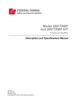
Figure 9 Typical Pole Installation
GROUND LEVEL
GROUND RODS
ULTRAVOICE CONTROLLER
BATTERY CABINET
RADIO ANTENNA
FIBERGLASS PROJECTORS
100 WATT DRIVER EA.
MOUNTING BRACKETS
DRIVER ACCESS
(IF REQUIRED)
(Sold Separately)
PANEL
VERTICAL SUPPORT
STRUCTURE
STAINLESS STEEL

18
Installation Instructions
Directional Speaker Array (Models DSA2, DSA4, and DSA6)
Federal Signal www.fedsig.com
Wood Utility Pole Installation
To install a wood utility pole:
1. Mount the upper DSA bracket, obtained as an option, at the top of the pole with the
proper orientation. Secure the DSA bracket to the utility pole with three 1/2 by 4inch
long galvanized lag bolts and three 1/2 inch flat washers. (Bolts and washers are
supplied by the installer.) See Figure 3.
2. Measure 12 inches down the pole from the center of the upper bracket to the point
that will be at the center of the DSAMK1 bracket.
3. Align the lower DSAMK1 bracket so it is in vertical alignment with the upper bracket.
4. Mount the lower DSAMK1 bracket using three 1/2 by 4 inch long galvanized lag bolts
and three 1/2 inch flat washers.
5. Remove and save the mounting bolts from the DSA.
6. Lift the array into position, with the cable coming out the bottom, and loosely secure
it to the previously installed upper DSA bracket at the outermost bracket holes using
the hardware previously removed.
7. Depending on how the array is mounted:
• If the array is to be mounted facing a horizontal plane, attach it to the DSAMK1
lower bracket in the outermost bracket holes using the hardware previously
removed.
• If the array is to be mounted so that it is pitched downward at a 15° angle, attach it
to the lower bracket at the innermost bracket holes using the previously removed
hardware.
8. Tighten all array mounting bolts.
Repeat steps 1-8 for each array in the installation.
Concrete or Metal Pole Installation
If the metal pole has a top of the pole plate, use the DSAMKSP to mount it to the pole’s
top. The DSAMKSP has all hardware to mount to the top of the pole and to mount one
DSA. If additional DSA speakers are to be mounted, use the DSAMKSPB45 kit. You can
use all brackets on wood, concrete, or metal utility poles.
Table 7 Bracket Options for Size of Pole
Size of Pole Mounting Bracket
For poles 4.5 inches or larger Use two I-IP100-PMW mounting brackets with
banding and a DSAMKSPB45 kit
For poles between 2-1/2 and 4.5 inches Use one DSAMKSPB45 kit and two I-IP100-PM
For poles 2-3/8 inches or smaller Use one DSAMKSPB23 and two I-IP100-PM
Pay careful attention to the orientation of these attachments to the poles. Once in place,
the speakers will project the loudest sounds in the directions that the brackets face.
When the installation requires the use of the DSAMK4 mounting bracket, you must make
a circular plate and rigidly attach to the top of the pole. Figure 15 shows the required bolt-
hole pattern for those brackets.

19
Installation Instructions
Description, Specications, and Installation Manual
Federal Signal www.fedsig.com
NOTE: The pole top mounting holes are at a 45° angle to the speakers’ horizontal
centerline.
The balance of the installation is similar to that for a wooden utility pole installation,
except that the installer will provide grade 5 machine screws, washers, and nuts for the
attachment of the siren brackets to the pole brackets.
The DSAMK1 drawing shows the bolt-hole pattern that the new bracket must be attached
to. See Figure 10.
Figure 10 DSAMK1 Bracket Dimensions
4" x .53" x 1" Slot
2.5"
8"
13"
3x Ø 0.53"
2"
2"
Figure 11 DSAMK1 Bracket Picture

20
Installation Instructions
Directional Speaker Array (Models DSA2, DSA4, and DSA6)
Federal Signal www.fedsig.com
Figure 12 DSAMKSPB45 Bracket Dimensions
4" x .53" x 1" Slot
13"
2.5"
4"
8"
3/8-24"
set screw
5"
2 x .41"
Figure 13 DSAMKSPB45 Bracket Picture
Page is loading ...
Page is loading ...
Page is loading ...
Page is loading ...
Page is loading ...
Page is loading ...
Page is loading ...
/