Page is loading ...

PANAMAX® MIW-B&O Installation
STEP 1:
STEP 2:
STEP 3:
STEP 7:
NOTE: Only for use with 15 Amp branch circuits utilizing 14 or 12 gauge wire.
STEP 4:
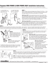
Strip the ends of both PowerLink® cables and connect them to the screw-down terminal
as labeled. Both PowerLink® cables will connect to the same terminal block.
STEP 5:
STEP 6:
Secure the cables with the provided cable ties.
STEP 8:
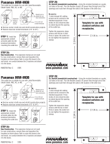
Cut a 4 inch wide by 3 3/ inch high hole in the wall for the AC wires, PowerLink® and/or MasterLink® cables.
For new construction (pre-wire) use a Carlon new-work electrical box (Model B122A) and a
Carlon low voltage add-on bracket (Model SC100SC).
Run the AC wires through the lower-left entry of the outlet box. No more than 1 inch of
wire sheath should extend into the outlet box. 3 inches of wire should be able to extend
beyond the opening of the outlet box. Install the outlet box into the right side of the hole.
Slide the signal-side cover onto the PowerLink® and/or MasterLink® cables.
Strip 1 1/2 inches of jacket off of the signal cables. Punch down the MasterLink® wires onto
the IDC terminals as labeled, with the cable oriented toward the front of the protector.
Fold the cables back toward the rear of the protector. Slide the signal-side cover
down the wires and into place. Secure the cover with the screw provided.
Strip 1/2 inch of insulation off the AC wires and attach to the wire jumpers using
the included wire nuts.
Neatly fold the AC wires as you install the protector into the wall with the AC side fitting into the
outlet box and secure with the with the AC side fitting into the outlet box and secure with the included screws.
NOTE: Only the right side screws are used to mount the protector into the included
outlet box. The left side screws are held on with the included plastic washers.
All four screws are used when mounting the protector to a new-work electrical box and add-on bracket.
1690 Corporate Circle, Petaluma, CA 94954 • Toll Free 800-472-5555 • Fax 707-283-5901 • www.panamax.com
The Power Specialist Since 1975
INS9802 REV. C 9/03
PowerLink and MasterLink are registered trademarks of Bang and Olafson Corp.
120VAC, 60Hz, 15A max
UL 1449 Suppression Voltage: .............330V L-N,
400V L-G,
400V N-G
Energy Dissipation: ..............................675 Joules (8x20ms)
Current Capacity:..................................26,000 Amps (8x20ms)
Input Connector: ..............Punch-down terminals
Output Connector:............MasterLink
Pins connected/protected..
1-3, 11-16
Limiting Voltage:..............15V
Insertion Loss:.................-0.05dB, 1Hz-50kHz
Crosstalk:.........................-81dB, 1Hz-50kHz
Input Connector:...................................8-position terminal block
Output Connector:.................................8-pin DIN
Pins connected / protected:.................ALL
Limiting Voltage:...................................15V
Insertion Loss:......................................-0.05dB, 1Hz-50kHz
Crosstalk:..............................................-81dB, 1Hz-50kHz
7
5
5
4
3
1
2
POWERLINK® SPECIFICATIONS
MASTERLINK® SPECIFICATIONS
AC SPECIFICATIONS
3 3/4 in.
4 in.
/


