Page is loading ...

LTR4-512
LTR8-512
LTR8-512M
Master Clock
Installation & User's Guide

Lathem, the Lathem logo, LTR4-512, LTR8-512, LTR8-512M, Radio Sync, LTR MasterLink, Terminal Manager and
PayClock
are registered trademarks of Lathem Time Corporation. Other product names mentioned in this manual
may be trademarks of their respective companies and are hereby acknowledged.
WARNING: Changes or modifications to this product not expressly approved by the party responsible for
compliance could void the user’s authority to operate this equipment.
THIS EQUIPMENT COMPLIES WITH FCC CLASS-B REQUIREMENTS
PURSUANT SUBPART J OF PART-15
This device complies with Part 15 of the FCC Rules. Operation is subject to the following two conditions: (1)
this device may not cause harmful interference, and (2) this device must accept any interference received,
including interference that may cause undesired operation.
WARNING: Changes or modifications to this product not expressly approved by the party responsible for
compliance could void the user’s authority to operate this equipment.
NOTE: This equipment has been tested and found to comply with the limits for a Class B digital device, pursuant to
Part 15 of the FCC Rules. These limits are designed to provide reasonable protection against harmful interference
in a residential installation. This equipment generates, uses, and can radiate radio frequency energy and, if not
installed and used in accordance with the instructions, may cause harmful interference to radio communications.
However, there is no guarantee that interference will not occur in a particular installation. If this equipment does
cause harmful interference to radio or television reception, which can be determined by turning the equipment off
and on, the user is encouraged to try to correct the interference by one or more of the following measures:
- Reorient or relocate the receiving antenna.
- Increase the separation between the equipment and receiver.
- Connect the equipment into an outlet on a circuit different from that to which the receiver is connected.
- Consult the dealer or an experienced radio TV technician for help.
This Class B digital apparatus complies with Canadian ICES-003.
Cet appareil numerique de la classe B est conforme a la norme NMB-003 du Canada.
Copyright © 2010 Lathem Time Corporation. All rights reserved.
Lathem Time Corporation
200 Selig Drive, SW
Atlanta, GA 30336
www.lathem.com
Document #USG0014S
Revised 12-18-2012

Table of Contents
Welcome..........................................................................................................1
Step 1 - Mounting the Master.................................................................................2
SURFACE MOUNT....................................................................................................2
SEMI-FLUSH MOUNT ................................................................................................3
RACK MOUNT .......................................................................................................5
HIDDEN POWER SUPPLY MOUNT ....................................................................................6
Step 2 – Wiring the Master ....................................................................................8
POWER SUPPLY – LTR8.............................................................................................8
POWER SUPPLY – LTR4.............................................................................................9
Step 3 – Setting Up the Master ...............................................................................11
Function Descriptions ..........................................................................................18
QUICK CHECK COMMANDS ..........................................................................................18
QUICK CHECK COMMAND [*] STATUS ...............................................................................18
QUICK CHECK COMMAND [1] EDIT KEYS ............................................................................18
QUICK CHECK COMMAND [3] 12/24 HOUR DISPLAY................................................................18
Program Keys ....................................................................................................18
[0] = PASSWORD....................................................................................................19
[1] = SET DATE AND TIME ..........................................................................................19
[2]=SELECT CLOCK CONTROL ......................................................................................21
[3]=MANUAL BELL CONTROL .......................................................................................21
AUTO BELL TEST....................................................................................................22
[4]=PROGRAM SCHEDULES..........................................................................................22
[6]=ENABLE OR DISABLE CIRCUITS..................................................................................26
[7]=DAYLIGHT SAVINGS ............................................................................................26
[8]=CHANGE ACTIVE SCHEDULE ....................................................................................26
[9]=SYNC CLOCKS ..................................................................................................27
[A]=PROGRAM HOLIDAYS ...........................................................................................28
[B]=COMMUNICATIONS (LTR8-512 AND LTR8-512M ONLY) ......................................................29
[C]=CHANGE PASSWORD ...........................................................................................29
APPENDIX A - SPECIFICATIONS ................................................................................30
APPENDIX B – DAYLIGHT SAVINGS COUNTRY CODES .......................................................31
APPENDIX C1 - SECONDARY CLOCK TYPE CODES ...........................................................32
APPENDIX C2 - WIRING SECONDARY CLOCKS ................................................................33
APPENDIX D - WIRING DIAGRAMS: POWER, BELLS, ETC. ..................................................50
FIG. D1 - TERMINAL BLOCK ‘P4’................................................................................50
WIRING THE LTRx-512 FOR 120VAC (nom.) OPERATION...............................................50
WIRING THE LTRx-512 FOR 220/240VAC (nom.) OPERATION .........................................50
FIG. D2 - TYPICAL SIGNAL DEVICE WIRING ...................................................................51
FIG. D3 - COMPUTER CABLE ....................................................................................52
FIG. D4 - RS-232 CABLE .........................................................................................52
FIG. D5 - SYNCHING UP TO 60 RS-485 TIME SYNC DEVICES.................................................53
FIG. D6 - LTRX-512 USED AS SLAVE TO ALLOW 30 EXTRA RS-485..........................................53
FIG. D7 – COMMUNICATION TERMINAL BLOCK ...............................................................54
FIG. D8 - POWER SUPPLY TERMINAL BLOCKS.................................................................56
APPENDIX E – INSTALL THE OPTIONAL MODEM .............................................................57
APPENDIX F – Connecting the LTR-GPS Satellite Receiver / Synchronizer ............................58
APPENDIX G – POWER SUPPLY SCHEMATICS.................................................................59

LTRx-512 Installation and User’s Guide
1
Welcome
Thank you for purchasing your new MASTER CLOCK. You can use your new Master to ring bells or turn on
circuits for up to 99 seconds, as well as to synchronize the time on secondary wall clocks or devices.
This manual covers 3 models of MASTER clocks: the LTR4-512, the LTR8-512 and the LTR8-512M
LTR4-512 LTR8-512 LTR8-512M
System Clock
Correction
1 correction type
running, plus RS485
correction
Up to 2 like or dissimilar
correction types running
simultaneously, plus RS485
correction
Up to 2 like or dissimilar
correction types running
simultaneously, plus
RS485 correction
Bell Circuits 4 with no clock
correction
2 with 1 clock
correction
8 with no clock correction
6 with 1 clock correction
4 with 2 clock correction
8 with no clock correction
6 with 1 clock correction
4 with 2 clock correction
Certifications UL, cUL,
FCC
UL, cUL,
FCC, DOC (internal modem
option)
UL, cUL,
FCC, DOC (internal
modem)
PC Interface
Software
None RS-232, RS-485,
Ethernet (requires TXTOSER
+ Cable)
RS-232, RS-485,
Modem , Ethernet
(requires TXTOSER +
Cable)
Atomic clock
synchronization
Yes. Requires LTR-GPS Yes. Requires LTR-GPS or
MasterLink software
Yes. Requires LTR-GPS or
MasterLink software
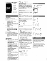
If your Master has 4 lights on the front panel, then you have the model LTR4-512
If your Master has 8 lights at the left of the front panel, then you have the model LTR8-512. If the TR
light at the keypad is lit, then you have the model LTR8-512M
CLK 1
1 2 3 4
cancel ent er
1
2
3
4
5
6
7
8
9
0
*
#
SD
TR
RD
CD
CLK 2 CLK 1
1 2 3 4
5 6 7 8
cancel ent er
1
2
3
4
5
6
7
8
9
0
*
#

LTRx-512 Installation and User’s Guide
2
Step 1 - Mounting the Master
The Master comes ready to surface mount on the wall. However, you can also install the Master in a
standard 19" rack, recess the power supply into the wall or hide the power supply in the floor or ceiling
and hang only the display unit on the wall with optional hardware.
A qualified electrician who understands the electrical code in your area should install your Master. The
installation should not require any special tools, but may require extra hardware, wire, etc. as required
by your local electrical code.
Surface Mount
Power Supply Box
Display Unit
Wall Mount Cover

LTRx-512 Installation and User’s Guide
3
To surface mount the Master
1. Place the Master on its back with the display unit facing up and the keypad to the right
2. Remove the two screws from just above the display unit
3. Lift the display unit up and away from you. Note that two rivets at the bottom of the cover
prevent you from lifting it straight up
4. Unplug the ribbon power cable from the back of the display unit
5. Set the display unit aside
6. Place two wall anchors and #8 screws 10 inches apart and level on the wall where you want
to mount the Master
7. If needed, place two wall anchors 5 inches below the first two screws
8. Hang the power supply onto the top two screws using the keyholes on the back
9. Screw two more #8 screws through the two holes at the bottom of the power supply into
the wall anchors
10. Follow the wiring steps in step 2
11. Reconnect the ribbon cable
12. Replace the display unit using the two screws that you earlier removed
Semi-Flush Mount
You can set the power supply portion of the Master into the wall. See the steps below and refer to
the Surface Mount drawing to semi-flush mount your Master. A competent electrician should mount
the Power Supply Box inside the wall
To semi-flush mount the Master
1. Place the Master on its back with the display unit facing up and the keypad to the right
2. Remove the two screws from just above the display unit
3. Lift the display unit up and away from you. Note that two rivets at the bottom of the cover
prevent you from lifting it straight up
4. Unplug the ribbon power cable from the back of the display unit
5. Set the display unit aside
6. The power supply measures 12" wide x 6" high x 3 3/8" deep. The cover extends ½" around
the 12" x 6" dimensions. Cut a hole roughly 12¼" x 6¼" in the wall between two studs where
you want to hang your Master
7. Cut two blocks of wood for filler and attach them to the studs
8. Using the two holes on each side of the power supply, screw it to the blocks
9. Follow the wiring steps in step 2
10. Plug the ribbon cable
11. Replace the display unit using the two screws that you earlier removed

LTRx-512 Installation and User’s Guide
4
Lowering the Display Unit during Testing
With a Semi-Flush or Surface mount, you can hang the display unit below the back box when testing
the Master and its circuits. To lower the display unit, remove the two screws that attach the display
unit to the back box. Lift the unit up and away from the back box, leaving the ribbon cable plugged
in. For Semi-Flush mounts, remove the green communications plug from the back of the display
unit, so it can sit flat against the wall. Swing the two hooks on the back of the unit up and hook
them over the bottom edge of the back box. You can use the keypad to turn on circuits or program
the Master, as well as access the relay and connector blocks inside the back box

LTRx-512 Installation and User’s Guide
5
Rack Mount
The LTR8-512 and LTR8-512M come with two L-shaped brackets (optional on the LTR4-512) so you
can install your Master in a standard 19-inch rack
To install the Master in a 19-inch rack
1. Place the Master on its back with the display unit facing up and the keypad to the right
2. Remove the two screws from just above the display unit
3. Lift the display unit up and away from you. Note that two rivets at the bottom of the cover
prevent you from lifting it straight up
4. Unplug the ribbon power cable from the back of the display unit
5. Set the display unit aside
6. Detach the display unit from the wall mount cover by removing the 4 screws on the back of
the display unit (IMPORTANT: These screws are the correct length so they do not interfere
with the circuit board inside the display unit. Using any other screws voids any warranty)
7. Remove the rectangular knockout near the top of the power supply
8. Using the 4 screws that you removed from the display unit, attach the display unit to the
side of the power supply. You can fit a #1 Philips screwdriver with an 8 inch blade through
the holes opposite the 4 screw holes
9. Plug the ribbon cable from the power supply into the display unit
Power Supply Box
Display Unit
Brackets

LTRx-512 Installation and User’s Guide
6
10. Remove the two screws from the side of the display unit
11. Using these same screws, attach an “L” bracket (or ear)
12. Repeat to attach the other ear
13. Mount the unit in the rack
14. Follow the wiring steps in the next chapter before attaching the box cover
15. Attach the furnished cover to the power supply using four 6-32 screws (two of these screws
you removed from the display unit)
Hidden Power Supply Mount
You can hide the power supply portion of the Master above a dropped ceiling, under a raised floor
or behind a wall, up to 8 feet away from the display unit. This allows you to hide the cables and
gives a more pleasing look to your Master. To mount the Master this way, you must purchase the
8-foot connection cable
To hide the power supply
Place the Master on its back with the display unit facing up and the keypad to the right
Remove the two screws from just above the display unit
Lift the display unit up and away from you. Note that two rivets at the bottom of the cover prevent you
from lifting it straight up
Unplug the ribbon power cable from the back of the display unit
Set the display unit aside
Detach the display unit from the power supply cover by removing the 4 screws on the back of the
display unit (IMPORTANT: These screws are the correct length so they do not interfere with the circuit
board inside the display unit. Using any other screws voids any warranty)
Unplug the ribbon cable from the power supply board
Remove a knockout in the power supply
Pass the end of the 8-foot connection cable with the Ground wire through the opening using proper
strain relief hardware.
Connect the communication cable. When properly installed, the cable will face away from the
transformer
8 foot cable
(optional)
Power Supply Box
Display Unit

LTRx-512 Installation and User’s Guide
7
Attach the ground wire to one of the lower power supply mounting screws
Note: UL regulations require that you do NOT place high voltage (120V) and low voltage
communication cables in the same conduit or through the same knockout holes
• Follow the wiring steps in step 2
• For the cleanest installation, mount the display unit over a standard “double gang” 4-inch
electrical box
• Route the other end of the 8-foot connection cable to this electrical box
• Place two #8 screws, 12 inches apart and level, ½-inch down from the top of the electrical box
• Connect the 8-foot connection cable and any communication cables to the display unit
• Check your connections, then turn your Master on using the On/Off switch on the power supply
board
• Attach the furnished cover to the power supply using four 6-32 screws (two of these screws you
earlier removed from the display unit)

LTRx-512 Installation and User’s Guide
8
Step 2 – Wiring the Master
Wire the display panel and power relay units for bell control and clock synchronization. Refer to the
diagrams in Appendix C2 for more details. Until you complete this part of the wiring, do not turn on
the AC power to P4, and keep the power/relay unit’s toggle switch turned “OFF”
(Note: The LTR4-512 does not contain Terminal Block P3)
Power Supply – LTR8
TERMINAL BLOCK ‘P4’
WIRING THE LTR8-512 FOR 120VAC
(nom.) OPERATION
J1 installed between 3 & 4 and J2
installed between 5 & 6
TERMINAL BLOCK ‘P4’
WIRING THE LTR8-512 FOR 220/240VAC
(nom.) OPERATION
J1 installed between 4 & 5

LTRx-512 Installation and User’s Guide
9
Power Supply – LTR4
Your Master is already setup for 120VAC operation. If you need to wire it for
220/240VAC, change the jumper settings as shown in the drawings on page 8.
TERMINAL BLOCK ‘P4’
WIRING THE LTR8-512 FOR 120VAC
(nom.) OPERATION
J1 installed between 3 & 4 and J2
installed between 5 & 6
TERMINAL BLOCK ‘P4’
WIRING THE LTR8-512 FOR 220/240VAC
(nom.) OPERATION
J1 installed between 4 & 5

LTRx-512 Installation and User’s Guide
10
We recommend using stranded wire inside the Power Supply Box. Stranded wire allows for a firm
connection to the Quick Connect terminals. Stranded wires are also less likely to interfere with the
relay board components. If you must use solid wire, join the stranded wire to the solid wire in another
box
Note that applying 220/240 VAC power to a system not setup for that voltage level can severely
damage its electronic parts
• Attach the supplied quick-connects to the wires as needed
• Plug the quick-connects into the terminal block, as shown in the drawings above. Failure to
properly connect the ground wire can increase interference and cause unsafe operating
conditions
• While the Master is fused internally to protect its electronics, you must also fuse the incoming AC
line as required by your local electrical code. You should connect the unit to a dedicated 10 Amp
circuit. You may need to add external MOV’s or diodes to sync a specific clock type – see Appendix
C1 for the wiring diagram of your type clock. Appendix D shows wiring diagrams for bell circuits and
communications
• Complete any mounting steps in the previous chapter before turning on the power supply
• Turn the toggle switch in the power supply to the “ON” position. The display may show the message
SYSTEM RECOVERY IN PROGRESS" for about 2 minutes, then you will see the date and time
• Fasten the cover to the power supply
EXTERNAL PULSE-SYNC
Your Master can synchronize to other systems if needed. For example, if you have a non-compatible
time clock that the Master cannot synchronize, but it has a built-in bell ringer. By shorting
terminals 7 & 8 on terminal block P1, or terminals 6 & 7 of the communications terminal on the
back of the display unit, the Master will immediately reset to 00:00 (midnight). If you can program
the other device to close its circuit at 00:00 (Midnight) then the two systems will remain reasonably
in sync. WARNING: DO NOT APPLY POWER TO THESE CONNECTIONS – only close the circuit for a
short time (Duration must be at least 1, but not more than 2 seconds)

LTRx-512 Installation and User’s Guide
11
Step 3 – Setting Up the Master
If you will use the Master to sync clocks, you must first use relays #7 & #8 (terminal block P1) for
synching. If you have an LTR8-512 or LTR8-512M and will use a second clock type, you must use
relays #5 & #6 (terminal block P2) for those clocks
Bell Zone
#1
Bell Zone
#2
Bell Zone
#3
Bell Zone
#4
Bell Zone
#5
Bell Zone
#6
Bell Zone
#7
Bell Zone
#8
Relay #1 Relay #2 Relay #3 Relay #4 Relay #5 Relay #6 Relay #7 Relay #8
---Clock Sync #2--- ---Clock Sync #1---
Here are some suggested ways to program your Master’s relays:
• Eight (8) bell zones that can last from 1 second to 99 seconds. Use this setup if your
Master will not synchronize secondary clocks (other than DDCx-RS types).
• Six (6) bell zones and one electro-mechanical wall clock sync control. Use this setup if
your Master will sync only one type of clock in one string.
• Four (4) bell zones and two electro-mechanical wall clock sync controls. Use this setup if
you will synchronize two clock types, or if you have two strings of clocks (typically 20 to
35 clocks to a string).
The steps below lead you through getting the Master up and running.
3A - Enter the Password
The user password allows you to access user functions, but you must use the administrator password to
access advanced functions. You can change the user password, but you cannot change the administrator
password. To keep the administrator functions secure, only give this guide to authorized personnel. All
factory programmed passwords can be spelled out using the letters of a telephone keypad. For
example, the administrator password is 332537 or DEALER. Perform the following keypad entries to
enter the administrator password.
Step Press See on Display .
1 [#][0][#] PASSWORD 000000
2 [3][3][2][5][3][7] PASSWORD 332537
3 [#] ADMINISTRATOR
PASSWORD ACCEPTED
The display will return to the time and date after 3 seconds.
Note that if you stop using the keypad for over 5 minutes, you must re-enter your password
3B - Set the Date and Time

LTRx-512 Installation and User’s Guide
12
To set the date and time, select Function [1] by keying [#][1][#]
Enter the numbers for the month, date and year (4-digit year), then press [#], such as
[0][4][0][3][2][0][0][3][#] shown below:
Enter a number [1] - [7] for the day of the week, Sunday through Saturday:
[1]=Sunday [2]=Monday [3]=Tuesday [4]=Wednesday
[5]=Thursday [6]=Friday [7]=Saturday
For example, if you press [5], the display shows
Press [#] to confirm or [*] to try again
Once you press [#], enter the time of the next upcoming minute, using either 12-hour or 24-hour
format, then press [#]. (If using 24-hour format, enter midnight as 00:00)
For example, if the current time is 08:59, enter: 09:00
ENT.DATE: 04-03-2003
ENTER DAY-OF-WEEK: D
1=SUNDAY..7=SATURDAY
ENT.DATE: 04-03-2003
TODAY IS THURSDAY
ENTER TIME: HH:MM
SELECT [0]PM / [1]AM
ENT.DATE: 04-03-2003
TODAY IS THURSDAY
ENTER TIME: 09:00
SELECT [0]PM / [1]AM

LTRx-512 Installation and User’s Guide
13
If you enter a time less than 13:00 (1:00 PM), then you will see
SELECT [0]PM / [1]AM
Press [0] for PM or [1] for AM. If you choose ‘PM’, then the time will display in 24-hour format to
confirm your entry
Press the [#] key at the top (‘00’ seconds) of the new minute to accept. If the time or date is
incorrect, press [*] to cancel and try again.
The display will now show the time and date you just entered. You can toggle between the 12-hour
and 24-hour display using “Quick Check” command [3]
Make sure you enter the correct date and day, because the schedules you setup depend on the
accuracy of these choices
3C - Enable the Relays
Use Function [6] to enable any control relays that you want to use.
The Enable Circuits function only enables you to use certain relays. It does not turn them on. Use
Function [3] or [4] to actually turn on these relays
Step Press Display
1 [#] SELECT FUNCTION CODE
2 [6] [6] =ENABLE CIRCUITS
3 [#] SELECT ACTIVE
BELL ZONES 12345678
CLOCK CKTS
PRESS [#] IF CORRECT
4 [1] - [8] Enter the circuit numbers that you want to enable
or disable.
5 [#] When you see all the circuit numbers you want
enabled, press [#]
ENT.DATE: 04-03-2003
TODAY IS THURSDAY
ENTER TIME: 21:00
PRESS [#] IF CORRECT

LTRx-512 Installation and User’s Guide
14
3D - Choose Clock Types
If you will use the Master to synchronize electro-mechanical wall clocks (analog or digital), then use
Function [2] to choose the clock type for Clock #1 and/or Clock #2, following the instructions below.
Clock Control Codes can be found in Appendix C1.
NOTE: You do not need to enter any special setup to make the Master synchronize Lathem time
sync devices (DDC4R, LTR-0, DWA-S and ATX6) using the Master’s RS-485 SYNC ports
NOTE: The LTR4-512 can only synchronize one type of secondary system
Start this function by pressing [#][2][#]
Enter the 2-digit code for CLOCK CIRCUIT 1, then press [#]. If you entered a code other than ‘00’, and
you have a LTR8-512 or LTR8-512M, you will see
Enter the code for CLOCK CIRCUIT 2, or [0][0] if you will not use a CLOCK2, then press [#]
PRESS [#] IF CORRECT
Enter [#] to confirm or [*] to cancel and try again.
For future reference, write the programmed Clock Type Codes on the lines, below:
Clock Circuit 1:__________________ Clock Circuit 2: _____________________
ENABLE CLOCK CIRCUIT
SELECT CLK1 CODE: NN
[#] FOR CODE LIST
ENABLE CLOCK CIRCUIT
SELECT CLK2 CODE: NN
[#] FOR CODE LIST

LTRx-512 Installation and User’s Guide
15
3E - Test Bell Circuits
Manual Bell Control
Use Manual Bell Control Function [3] (described on Pg. 20 to test selected bell circuits. Press [#][3][#]
to start this function
Auto Test the Bells
Use the Auto Bell Test feature to turn on all bell relays once per minute at the start of each minute.
Once you start this function, you can test the continuity of your bell wiring circuits. Use the “hidden
code” 2355878 [BELLTST] to start the Auto Bell Test. When you enter this code, ignore anything that
displays on the screen
Use Function [6] to disable any relays that you do not want to use in your testing
Once you finish testing, make sure you enter the hidden code again to stop the Auto Bell Test and use
Function [6] to enable any relays that you earlier disabled
3F – Set Daylight Savings
Your Master comes set to adjust for Daylight Savings Time in the United States. If you live outside the
United States or if your region does not observe daylight savings, use Function [7]
(Described on Pg. 26); otherwise, skip to Step 3g.
MANUAL BELL CONTROLS
1-2-3-4-5-6-7-8
PRESS AND HOLD [#]
TO EXECUTE. [*]TO END

LTRx-512 Installation and User’s Guide
16
3G – Setup Communication
The “factory default” communication settings (LTR8-512 and LTR8-512M only) are:
Baud Rate: 9600
Terminal ID#: 065
Use Function [B] (described on Pg. 30) if you if you need to change these settings for MasterLink
configurations involving multiple Masters,
You can setup your LTR8-512 with LTR MasterLink using RS-232 (serial), RS-485 (networked), Modem
(remote), or Ethernet (requires TXTOSER accessory) Communications.
You must enter these same settings for your LTR8-512 in the LTR MasterLink software
Congratulations! You have finished the basic setup of your LTRx-512 Master.
Basic Setup is Complete!
All of the programmed parameters have been stored in the Master’s protected memory and will be
retained in the event of power failure, brown-outs, etc.
The Master will exit itself out of Program Mode once you stop using the keypad for 5 minutes. If you
wish to exit programming mode immediately, to prevent others from accessing the Master Clock, simply
enter an invalid password. (For example)
Press Display
[#] SELECT FUNCTION CODE
[0] [0]=ENTER PASSWORD
[#] 99 [#] PASSWORD: 000099

LTRx-512 Installation and User’s Guide
17
Additional Functions:
All of the Master’s functions are described in the next section of this guide. Remaining steps, which
may be performed “as needed” by the Installer or User, include the following:
Function
Number Programming Operation .
0 Enter Password
1 Set Date / Time
3 Manual Bell Control (Immediate Activation)
4 Program Bell Schedules
5 Program Schedule Change Dates
8 Change Active Schedule
9 Synch Clocks (after Wall Clock power failure)
A Program Holidays
C Change User Password
In particular, most Users will want to execute the following steps:
Enter their User Password (Function [0]),
Program Bell Schedules (Function [4]) and
Make at least one Bell Schedule “Active” (Function [8]).
Users may also want to:
Program Schedule Change Dates (Function [5]) for automating schedule changes
Program Holidays (Function [A]) if bells should not ring on those occasions
Change User Password (Function[C]) to prevent unauthorized tampering
Users who are unfamiliar with the technical specifications of the installation are urged to avoid
accessing functions that require the Administrator Password, as incorrectly reprogramming any of the
configuration parameters (Functions 2, 6, 7, B) could cause the system to function improperly.
/