Extron MDA 3A User manual

Category
Serial switch boxes
Type
User manual
1
MDA 3 Series • User Guide
This guide describes the installation and operation of the Extron MDA 3 Series Mini Distribution Ampliers (MDA).
FCC Class A Notice
This equipment has been tested and found to comply with the limits for a Class A digital device, pursuant to part15 of the
FCC rules. The ClassA limits provide reasonable protection against harmful interference when the equipment is operated in a
commercial environment. This equipment generates, uses, and can radiate radio frequency energy and, if not installed and used
in accordance with the instruction manual, may cause harmful interference to radio communications. Operation of this equipment
in a residential area is likely to cause interference. This interference must be corrected at the expense of the user.
NOTE: For more information on safety guidelines, regulatory compliances, EMI/EMF compatibility, accessibility, and related topics,
see the “Extron Safety and Regulatory Compliance Guide” on the Extron website.
Specifications Availability
Product specications are available on the Extron website, www.extron.com.
Introduction
The Extron MDA 3 Series are a family of eight one-input, three-output, video and audio distribution ampliers. The MDA series
distribution ampliers (DAs) split one composite video or S-video input and/or audio input for output to multiple destinations with
no loss of signal quality. The MDA are members of the Extron line of basic distribution ampliers, switchers, and associated video
accessories.
The MDAs distribute composite video, S-video (luminance (Y) and chrominance (C)), and/or balanced or unbalanced audio on
captive screw connectors, or unbalanced audio on RCA connectors, in the following combinations:
Distribution Amplifier
S-Video
Composite Video
Audio (Captive
Screw Connectors)
Audio (RCA
Connectors)
MDA 3SV
MDA 3SVA
MDA 3SV Dual
2
MDA 3V
MDA 3AV
MDA 3V Dual
2
MDA 3A
MDA 3A RCA
The MDAs ship with external desktop 12 V power supplies that accept 100 to 240 VAC, 50 Hz or 60 Hz input.
2MDA 3 Series • User Guide
Connections, Controls, and Indicator
Figure 1 show all of the combinations of connectors that you may encounter with your MDA.
MDA 3AV
POWER
12V
.34A MAX
LRLRLRLR
INPUT
OUTPUTS
1
2
3
BAL
1 2 3
UNBAL
1
I
N
O
U
T
2
3
MDA 3SVA
POWER
12V
.5A MAX
LRLRLRLR
INPUT
OUTPUTS
1
2
3
BAL
1 2 3
UNBAL
1
2
3
INPUT
OUTPUTS
MDA 3V
DUAL
POWER
12V
.5A MAX
1
2
3
INPUT
OUTPUTS
1
2
3
A
B
MDA 3V Dual,
Rear Panel
MDA 3AV,
Rear Panel
MDA 3SVA,
Rear Panel
1 2
3 4 3 4
58 6 7
5 38 86 47
Figure 1. MDA 3 Series Front and Rear Panels
S-video (MDA 3SV and MDA 3SVA)
a Input connectorsConnect an S-video input to this four-pin mini DIN connector.
b Out connector or Outputs (1 through 3) connectorsConnect up to three S-video devices to these four-pin mini DIN
connectors.
Composite Video (MDA 3V, MDA 3AV, and MDA 3V Dual)
c In connector or Input connectorConnect a composite video input to this BNC connector. On the Dual model, Input A and
Input B are completely separate inputs to two separate distribution amplifiers.
d Out connector or Outputs (1 through 3) connectorsConnect up to three composite video devices to these BNC
connectors. On the Dual model, the A output signals are identical to the A input, and the B output signals are identical to the B
input.
Audio on captive screw connectors (MDA 3AV, MDA 3SVA, MDA 3A)
e Audio Input connectorConnect a balanced or unbalanced audio input to this 3.5 mm, five-pole captive screw connector.
Connectors are included, but you must supply the audio cable. See figure 2 to wire a connector for the appropriate input type
and impedance level. High impedance is generally over 800 ohms.
Unbalanced Stereo Input
Balanced Stereo Input
Do not tin the wires!
Tip
Ring
Tip
Ring
Sleeves
Tip
Sleeve
Sleeve
Tip
LR
LR
inch
Figure 2. Captive Screw Input Connector Wiring
3MDA 3 Series • User Guide
NOTES:
The length of exposed wires is critical. The ideal length is 3/16 inch (5 mm).
If the stripped section of wire is longer than 3/16 inch, the exposed wires may touch, causing a short circuit.
If the stripped section of wire is shorter than 3/16 inch, wires can be easily pulled out even if tightly fastened by
the captive screws.
Do not tin the power supply leads before installing them in the connector. Tinned wires are not as secure in the
connector and could be pulled out.
When making connections for the MDA from existing audio cables, see gure 3. A mono audio connector consists
of the tip and sleeve. A stereo audio connector consists of the tip, ring and sleeve. The ring, tip, and sleeve wires
are also shown on the captive screw audio connector diagrams, gure 2 and gure 4.
Tip (Left) Sleeve (Gnd)
Tip (Left)
Ring (Right)
Sleeve (Gnd)
Tip Sleeve
Unbalanced Mono Unbalanced Stereo
Tip (Signal)
Sleeve (Gnd)
Figure 3. Phono Audio Connectors
f Audio Outputs (1 through 3) connectors — Connect up to three balanced or unbalanced audio devices to these 3.5 mm,
five-pole captive screw connectors. Connect audio devices, such as an audio amplier or powered speakers. See gure 4 to
properly wire an output connector.
Unbalanced Stereo Output Balanced Stereo Output
Do not tin the wires!
Tip
Ring
Tip
Ring
Sleeves
Tip
No Ground Here
No Ground Here
Tip
Sleeves
LR
LR
inch
Figure 4. Captive Screw Connector Wiring for Audio Output
ATTENTION: For unbalanced audio, connect the sleeves to the ground contact. DO NOT connect the sleeves to the
negative (-) contacts.
NOTE: The length of exposed wires is important. The ideal length is 3/16 inch (5 mm) (see the NOTES above for details).
g Bal(anced)/Unbal(anced) DIP switches — For each balanced audio output, set the associated DIP switch to the Balanced
(up) position. For each unbalanced audio output, set the associated DIP switch to the Unbalanced (down) position.
The balanced or unbalanced nature of the audio output is determined by the output connector wiring, not the audio input.
Each output can be balanced or unbalanced independently of the other two outputs.
68-607-01
Rev. E 10 13
Extron Headquarters
+800.633.9876 Inside USA/Canada Only
Extron USA - West Extron USA - East
+1.714.491.1500 +1.919.850.1000
+1.714.491.1517 FAX +1.919.850.1001 FAX
Extron Europe
+800.3987.6673
Inside Europe Only
+31.33.453.4040
+31.33.453.4050 FAX
Extron Asia
+65.6383.4400
+65.6383.4664 FAX
Extron Japan
+81.3.3511.7655
+81.3.3511.7656 FAX
Extron China
+86.21.3760.1568
+86.21.3760.1566 FAX
Extron Middle East
+971.4.299.1800
+971.4.299.1880 FAX
Extron Korea
+82.2.3444.1571
+82.2.3444.1575 FAX
Extron India
+1800.3070.3777
(Inside India Only)
+91.80.3055.3777
+91.80.3055.3737 FAX
© 2013 Extron Electronics All rights reserved. All trademarks mentioned are the property of their respective owners. www.extron.com
Power (All Models)
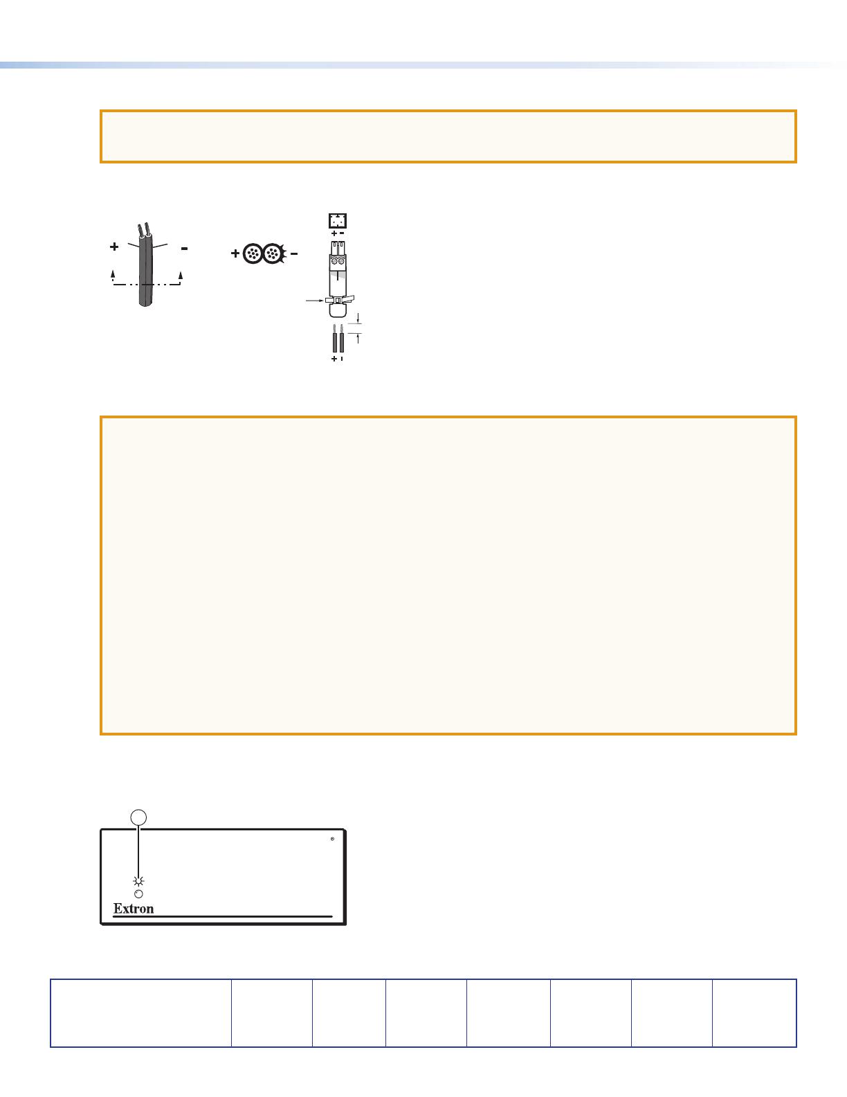
ATTENTION: Power supply voltage polarity is extremely important. Applying power with incorrect voltage polarity
could damage the power supply and the MDA. Identify the power cord negative lead by the ridges on the side of the
cord.
h Power connector — Plug the external 12 VDC power supply into this two-pole captive screw connector. The power supply
is included with the unit. Figure 5 shows how to wire the connector.
Power Supply
Output Cord
Orange Captive Screw
Connector
0.3 inch (7 mm) MA
X
SECTION A–A
Ridges
Smooth
AA
Tie Wrap
Figure 5. Power Connector Wiring
ATTENTION:
Always use a power supply supplied by or specified by Extron for use with the MDA. Use of an
unauthorized power supply voids all regulatory compliance certification and may cause damage to the
supply and the MDA.
Unless otherwise stated, the AC/DC adapters are not suitable for use in air handling spaces or in wall
cavities. The power supply is to be located within the same vicinity as the Extron AV processing equipment
in an ordinary location, Pollution Degree 2, secured to the equipment rack within the dedicated closet,
podium or desk.
The installation must always be in accordance with applicable provisions of National Electrical Code ANSI/
NFPA 70, article 75 and the Canadian Electrical Code part 1, section 16. The power supply shall not be
permanently fixed to building structure or similar structure.
The length of exposed wires is important. The ideal length is 3/16 inch (5 mm) (see the NOTES on page 3
for details).
To verify the polarity before connection, plug in the power supply with no load and check the output with a
voltmeter.
The two power cord wires must be kept separate while the power supply is plugged in. Remove power
before wiring.
As an alternative, an Extron P/S 100 Universal 12 VDC Power Supply can power multiple MDAs or other Extron 12 VDC
devices using only one AC power connector.
i Power LED When lit, this LED indicates power is applied to the MDA.
DISTRIBUTION AMPLIFIER
9
Front Panel, all MDA Models
Figure 6. MDA 3 Series Front Panel (All Models)
  • Page 1 1
  • Page 2 2
  • Page 3 3
  • Page 4 4

Extron MDA 3A User manual

Category
Serial switch boxes
Type
User manual

Ask a question and I''ll find the answer in the document

Finding information in a document is now easier with AI