Page is loading ...

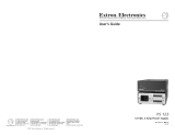
Installation Manual
12 VDC, 4 Amp Power Supply
68-1714-01 Rev. A
05 09
PS 124
Front cover

Precautions
This symbol is intended to alert the user of important
operating and maintenance (servicing) instructions in
the literature provided with the equipment.
This symbol is intended to alert the user of the
presence of uninsulated dangerous voltage within
the product’s enclosure that may present a risk of
electric shock.
Caution
Read Instructions • Read and understand all safety and operating
instructions before using the equipment.
Retain Instructions • The safety instructions should be kept for future
reference.
Follow Warnings • Follow all warnings and instructions marked on the
equipment or in the user information.
Avoid Attachments • Do not use tools or attachments that are not
recommended by the equipment manufacturer because they may be
hazardous.
Warning
Power sources • This equipment should be operated only from the power source
indicated on the product. This equipment is intended to be used with a main power
system with a grounded (neutral) conductor. The third (grounding) pin is a safety
feature, do not attempt to bypass or disable it.
Power disconnection • To remove power from the equipment safely, remove all power
cords from the rear of the equipment, or the desktop power module (if detachable),
or from the power source receptacle (wall plug).
Power cord protection • Power cords should be routed so that they are not likely to be
stepped on or pinched by items placed upon or against them.
Servicing • Refer all servicing to qualified service personnel. There are no user-
serviceable parts inside. To prevent the risk of shock, do not attempt to service
this equipment yourself because opening or removing covers may expose you to
dangerous voltage or other hazards.
Slots and openings • If the equipment has slots or holes in the enclosure, these are
provided to prevent overheating of sensitive components inside. These openings
must never be blocked by other objects.
Lithium battery • There is a danger of explosion if battery is incorrectly
replaced. Replace it only with the same or equivalent type recommended by
the manufacturer. Dispose of used batteries according to the manufacturer’s
instructions.
Ce symbole sert à avertir l’utilisateur que la
documentation fournie avec le matériel contient des
instructions importantes concernant l’exploitation et
la maintenance (réparation).
Ce symbole sert à avertir l’utilisateur de la présence
dans le boîtier de l’appareil de tensions dangereuses
non isolées posant des risques d’électrocution.
Attention
Lire les instructions• Prendre connaissance de toutes les consignes de
sécurité et d’exploitation avant d’utiliser le matériel.
Conserver les instructions• Ranger les consignes de sécurité afin de pouvoir
les consulter à l’avenir.
Respecter les avertissements • Observer tous les avertissements et consignes
marqués sur le matériel ou présentés dans la documentation utilisateur.
Eviter les pièces de xation • Ne pas utiliser de pièces de fixation ni d’outils
non recommandés par le fabricant du matériel car cela risquerait de poser
certains dangers.
Avertissement
Alimentations• Ne faire fonctionner ce matériel qu’avec la source d’alimentation
indiquée sur l’appareil. Ce matériel doit être utilisé avec une alimentation principale
comportant un fil de terre (neutre). Le troisième contact (de mise à la terre) constitue
un dispositif de sécurité : n’essayez pas de la contourner ni de la désactiver.
Déconnexion de l’alimentation• Pour mettre le matériel hors tension sans danger,
déconnectez tous les cordons d’alimentation de l’arrière de l’appareil ou du module
d’alimentation de bureau (s’il est amovible) ou encore de la prise secteur.
Protection du cordon d’alimentation • Acheminer les cordons d’alimentation de
manière à ce que personne ne risque de marcher dessus et à ce qu’ils ne soient pas
écrasés ou pincés par des objets.
Réparation-maintenance • Faire exécuter toutes les interventions de réparation-
maintenance par un technicien qualifié. Aucun des éléments internes ne peut être
réparé par l’utilisateur. Afin d’éviter tout danger d’électrocution, l’utilisateur ne doit
pas essayer de procéder lui-même à ces opérations car l’ouverture ou le retrait des
couvercles risquent de l’exposer à de hautes tensions et autres dangers.
Fentes et orices • Si le boîtier de l’appareil comporte des fentes ou des orifices, ceux-ci
servent à empêcher les composants internes sensibles de surchauffer. Ces ouvertures
ne doivent jamais être bloquées par des objets.
Lithium Batterie • Il a danger d’explosion s’ll y a remplacment incorrect de la batterie.
Remplacer uniquement avec une batterie du meme type ou d’un ype equivalent
recommande par le constructeur. Mettre au reut les batteries usagees conformement
aux instructions du fabricant.
Safety Instructions • English
Consignes de Sécurité • Français
Sicherheitsanleitungen • Deutsch
Dieses Symbol soll dem Benutzer in der im
Lieferumfang enthaltenen Dokumentation
besonders wichtige Hinweise zur Bedienung und
Wartung (Instandhaltung) geben.
Dieses Symbol soll den Benutzer darauf aufmerksam
machen, daß im Inneren des Gehäuses dieses
Produktes gefährliche Spannungen, die nicht isoliert
sind und die einen elektrischen Schock verursachen
können, herrschen.
Achtung
Lesen der Anleitungen • Bevor Sie das Gerät zum ersten Mal verwenden,
sollten Sie alle Sicherheits-und Bedienungsanleitungen genau durchlesen
und verstehen.
Aufbewahren der Anleitungen • Die Hinweise zur elektrischen Sicherheit
des Produktes sollten Sie aufbewahren, damit Sie im Bedarfsfall darauf
zurückgreifen können.
Befolgen der Warnhinweise • Befolgen Sie alle Warnhinweise und
Anleitungen auf dem Gerät oder in der Benutzerdokumentation.
Keine Zusatzgeräte • Verwenden Sie keine Werkzeuge oder Zusatzgeräte,
die nicht ausdrücklich vom Hersteller empfohlen wurden, da diese eine
Gefahrenquelle darstellen können.
Vorsicht
Stromquellen • Dieses Gerät sollte nur über die auf dem Produkt angegebene
Stromquelle betrieben werden. Dieses Gerät wurde für eine Verwendung mit einer
Hauptstromleitung mit einem geerdeten (neutralen) Leiter konzipiert. Der dritte
Kontakt ist für einen Erdanschluß, und stellt eine Sicherheitsfunktion dar. Diese
sollte nicht umgangen oder außer Betrieb gesetzt werden.
Stromunterbrechung • Um das Gerät auf sichere Weise vom Netz zu trennen, sollten
Sie alle Netzkabel aus der Rückseite des Gerätes, aus der externen Stomversorgung
(falls dies möglich ist) oder aus der Wandsteckdose ziehen.
Schutz des Netzkabels • Netzkabel sollten stets so verlegt werden, daß sie nicht im
Weg liegen und niemand darauf treten kann oder Objekte darauf- oder unmittelbar
dagegengestellt werden können.
Wartung • Alle Wartungsmaßnahmen sollten nur von qualiziertem Servicepersonal
durchgeführt werden. Die internen Komponenten des Gerätes sind wartungsfrei.
Zur Vermeidung eines elektrischen Schocks versuchen Sie in keinem Fall, dieses
Gerät selbst öffnen, da beim Entfernen der Abdeckungen die Gefahr eines
elektrischen Schlags und/oder andere Gefahren bestehen.
Schlitze und Öffnungen • Wenn das Gerät Schlitze oder Löcher im Gehäuse aufweist,
dienen diese zur Vermeidung einer Überhitzung der empndlichen Teile im
Inneren. Diese Öffnungen dürfen niemals von anderen Objekten blockiert werden.
Litium-Batterie • Explosionsgefahr, falls die Batterie nicht richtig ersetzt
wird. Ersetzen Sie verbrauchte Batterien nur durch den gleichen oder einen
vergleichbaren Batterietyp, der auch vom Hersteller empfohlen wird. Entsorgen Sie
verbrauchte Batterien bitte gemäß den Herstelleranweisungen.
Este símbolo se utiliza para advertir al usuario
sobre instrucciones importantes de operación y
mantenimiento (o cambio de partes) que se desean
destacar en el contenido de la documentación
suministrada con los equipos.
Este símbolo se utiliza para advertir al usuario sobre
la presencia de elementos con voltaje peligroso sin
protección aislante, que puedan encontrarse dentro
de la caja o alojamiento del producto, y que puedan
representar riesgo de electrocución.
Precaucion
Leer las instrucciones • Leer y analizar todas las instrucciones de operación y
seguridad, antes de usar el equipo.
Conservar las instrucciones • Conservar las instrucciones de seguridad para
futura consulta.
Obedecer las advertencias • Todas las advertencias e instrucciones marcadas
en el equipo o en la documentación del usuario, deben ser obedecidas.
Evitar el uso de accesorios • No usar herramientas o accesorios que no
sean especificamente recomendados por el fabricante, ya que podrian
implicar riesgos.
Advertencia
Alimentación eléctrica • Este equipo debe conectarse únicamente a la fuente/tipo
de alimentación eléctrica indicada en el mismo. La alimentación eléctrica de este
equipo debe provenir de un sistema de distribución general con conductor neutro
a tierra. La tercera pata (puesta a tierra) es una medida de seguridad, no puentearia
ni eliminaria.
Desconexión de alimentación eléctrica • Para desconectar con seguridad la acometida
de alimentación eléctrica al equipo, desenchufar todos los cables de alimentación
en el panel trasero del equipo, o desenchufar el módulo de alimentación (si fuera
independiente), o desenchufar el cable del receptáculo de la pared.
Protección del cables de alimentación • Los cables de alimentación eléctrica se deben
instalar en lugares donde no sean pisados ni apretados por objetos que se puedan
apoyar sobre ellos.
Reparaciones/mantenimiento • Solicitar siempre los servicios técnicos de personal
calificado. En el interior no hay partes a las que el usuario deba acceder. Para evitar
riesgo de electrocución, no intentar personalmente la reparación/mantenimiento
de este equipo, ya que al abrir o extraer las tapas puede quedar expuesto a voltajes
peligrosos u otros riesgos.
Ranuras y aberturas • Si el equipo posee ranuras o orificios en su caja/alojamiento,
es para evitar el sobrecalientamiento de componentes internos sensibles. Estas
aberturas nunca se deben obstruir con otros objetos.
Batería de litio • Existe riesgo de explosión si esta batería se coloca en la posición
incorrecta. Cambiar esta batería únicamente con el mismo tipo (o su equivalente)
recomendado por el fabricante. Desachar las baterías usadas siguiendo las
instrucciones del fabricante.
Instrucciones de seguridad • Español
Safety Precautions

VCCI Class B notice for ITE products (See the product’s specifications to determine
whether this class applies.)
この装置は、情報処理装置等電波障害自主規制協議会(VCCI)の基準に基づくクラスB情報技術装置で
す。この装置は、 家庭環境で使用することを目的としていますが、この装置がラジオやテレ
ビジョン受信機に近接して使用されると、受信
障害を引き起こすことがあります。
取扱説明書に従って正しい取り扱いをして下さい。
English translation: “This is a Class B product based on the standard of Voluntary Control Council for
Interference from Information Technology Equipment (VCCI). If this is used near a radio or television
receiver in a domestic environment, it may cause radio interference. Install and use the equipment
according to the instruction manual.”
ᅝܼ乏ⶹ•Ё᭛
䖭Ͼヺোᦤ⼎⫼᠋䆹䆒⫼᠋ݠЁ
᳝䞡㽕ⱘ᪡㓈ᡸ䇈ᯢDŽ
䖭Ͼヺো䄺ਞ⫼᠋䆹䆒ᴎݙ᳝ᲈ
䴆ⱘॅ䰽⬉य़ˈ᳝㾺⬉ॅ䰽DŽ
⊼ᛣ
䯙䇏䇈ᯢк• 䑩ㅸỀ䑩嬦嫿⡈⼆枼敆嬼䍇
夤ㆁ㙊⫊₩⏍Ề䑩嬵㕏ɿ
ֱᄬ䇈ᯢк• 䑩ㅸⷕ⪙⫊₩嬵㕏ᶧḦ⡈⭇㚦Ề
䑩ɿ
䙉ᅜ䄺ਞ• 䑩ㅸⷕ徶⫉ᷨ␂⏍䑩ㅸ㉈⊘ᵋ䗅ㆁ㙊⫊
₩⏍㐎ẝ嬵㕏ɿ
䙓ܡ䗑ࡴ• ᵎ壂Ề䑩嬦ᷨ␂⋃⒇㯢㙊㋩劑䗅₸ㅗ
弾⇡嫿⡈澤Ḧ忀₎⊲斪ɿ
䄺ਞ
⬉⑤• 嬦嫿⡈⌫倾Ề䑩ᷨ␂ᵋ㝈㕏䗅䑶㷑ɿ嫿⡈
⼆枼Ề䑩㙊♱一䗅Ờ䑶䰼丠Ờ䑶ɿ䩭ᵊ㚢一
澠♱一澡㕰⫊₩嫿㓾澤ᵎ倾ᵎ䑩ㅗ崴弈ɿ
ᢨᥝ⬉⑤• ᵻ⫊₩♱ḏ嫿⡈㈕㋊䑶㷑澤嬸㈕㋊ㆁ㙊嫿⡈⍏
ㅗ㞍暣䑶㷑䗅䑶㷑一澤ㅗḼẖ㋦ⅱⵃ䑶䰼丠䗅䑶㷑一ɿ
⬉⑤㒓ֱᡸ• ⣦Ⓟⵄ一澤忀₎埬嵪嵐澤ㅗ愎䆪㉥⋌ɿ
㓈ᡸ•ㆁ㙊丵Ἧ⼆枼䑲嫥嬂䗅丵Ἧ᷻⎙弜垍ɿ嫿⡈怩㯢
㙊䑩ㅸ⌰Ḧ㘵㊣䗅昷ḷɿᵻ忀₎℻䋱大䑶⊲斪ᵎ壂儫ⴲ
嬖☿㆔⹁嫿⡈䘗⪑丵Ἧ嬦嫿⡈ɿ
䗮亢ᄨ• 㙊ᷜ嫿⡈㙻⠴ᵋ㙊彛栏㤾ㅗ⪕澤⫄ḭ㕰䑩㚦敳㪣
㙻㒐だ₄ḷ弈䀮ɿᵎ壂䑩Ḽẖᵝ壀㉢Ẑ彛栏⪕ɿ
䫖⬉∴• ᵎ㪤䞯䗅㘵㊣䑶㮡ṛ㙊䅇㿹䗅⊲斪ɿ⼆枼Ề䑩ᵏ
⋃⫷㋩劑䗅䘹⍍ㅗ䘹弒⛌⌸䗅䑶㮡ɿ㉊䂨䑠ᷨ⋃䗅⸻
嫯⡅䍇ⷠ⹄䑶㮡ɿ
FCC Class B Notice
This equipment has been tested and found to comply with the limits for a Class B digital device,
pursuant to part 15 of the FCC Rules. These limits are designed to provide reasonable protection
against harmful interference in a residential installation. This equipment generates, uses, and can
radiate radio frequency energy and, if not installed and used in accordance with the instructions,
may cause harmful interference to radio communications. However, there is no guarantee that
the interference will not occur in a particular installation. If this equipment does cause harmful
interference to radio or television reception, which can be determined by turning the equipment
off and on, the user is encouraged to try to correct the interference by one or more of the following
measures:
• Reorientorrelocatethereceivingantenna.
• Increasetheseparationbetweentheequipmentandreceiver.
• Connecttheequipmentintoanoutletonacircuitdifferentfromthattowhichthereceiveris
connected.
• Consultthedealeroranexperiencedradio/TVtechnicianforhelp.
N
This unit was tested with shielded cables on the peripheral devices. Shielded cables must be used
with the unit to ensure compliance.

i
PS 124 12 VDC, 4 Amp Power Supply • Table of Contents
i
Table of Contents
Introduction .................................................................................... 1
Front and Rear Panel Features ................................................. 1
LED indicators............................................................................ 1
Input Power ............................................................................... 2
DC Outputs ................................................................................ 3
Connections .................................................................................... 4
Input power — using the IEC power cord ............................... 4
Input power — using the Flexible Conduit Adapter Kit ........ 4
UL guidelines .............................................................................5
Installing the exible conduit cable .........................................5
Output power — wiring the DC output connectors .............. 8
Installing the PS 124 .................................................................... 9
UL rack mounting guidelines ................................................... 9
Rack mounting ........................................................................ 10
Under-desk mounting ............................................................. 11
Above-projector mounting .................................................... 12
Specications ............................................................................... 15
Included Parts .............................................................................. 16
Accessories .................................................................................... 16
68-1714-01 Rev. A
05 09
All trademarks mentioned in this manual are the properties of their respective owners.

ii
PS 124 12 VDC, 4 Amp Power Supply • Table of Contents
Table of Contents, cont’d

PS 124 12 VDC, 4 Amp Power Supply • Installation Manual
1
Introduction
TheExtronPS124isahighperformance,plenumrated(with
optionalFlexibleConduitkit),12VDCpowersupply.The
autoswitchable100VACto240VACinputcansupplya
maximumcurrentof4ampsforuptoeightoutputs. Each
DCoutputisonatwo-polecaptivescrewconnector,withno
per-outputcurrentlimitation.Two-toneLEDsonthefrontand
rear panels indicate normal operation (green) and overload
condition (red).
TherackmountablePS124hasa1Uhigh,quarterrackwide,
9"deepmetalenclosure,allowingthePS124totakeadvantage
of a variety of mounting options.
Front and Rear Panel Features
All power and output connections are on the rear panel.
RED-OVERLOAD
P/S 124
12 VDC 4A POWER SUPPLY
OUTPUTS
RED-
OVERLOAD
100-240 50-60Hz 1.2A MAX.
OUTPUTS
RED-
OVERLOAD
100-240 50-60Hz 1.2A MAX.
12 V TOTAL OUTPUT 4A
12 V TOTAL OUTPUT 4A
D E FCC
Figure 1 — PS 124 front and rear panels
LED indicators
a
Power status LEDs—ThesefrontandrearpanelLEDsindicate
thePS124statusbylightingasfollows:
• Green when power is applied and current draw is normal
• Red indicates a current overload condition
C
Continued operation in an overload condition may
cause premature power supply failure.
• Unlit when an output is shorted
N
To identify the shorted output, unplug the outputs one at
a time until the LEDs light green.

PS 124 12 VDC, 4 Amp Power Supply • Installation Manual
PS 124, cont’d
2
Input Power
ApplypowertothePS124usingthesuppliedIECpowercord
(
b
) orbyinstallingtheoptionalFlexibleConduitAdapterKit
(Extronpart#70-228-02) (
c
).
b
IEC connector/power supply—PlugtheIECcordintothis
connectoranda100–240VACsource.
-OR-
c
Optional conduit adapter plate — The IEC connector and
adapter plate canbereplacedbythishalf-inchconduitEMT
(ElectricalMetallicTubing)adapterplate,asshowningure2.
See“Inputpower—usingtheFlexibleConduitAdapterKit,”
onpage4.
N
With the installation of the Flexible Conduit Adapter kit,
the PS 124 is suitable for use in air handling spaces and
meets all applicable requirements of UL 2043.
OUTPUTS
RED-
OVERLOAD
12 VDC TOTAL OUTPUT 4A
100-240 50-60Hz 1.2A MAX.
OUTPUTS
RED-
OVERLOAD
12 VDC TOTAL OUTPUT 4A
100-240 50-60Hz 1.2A MAX.
Extron
PS 124
12 VDC 4 A Power Supply
1 2345678
For plenum applications replace
this plate with optional flex conduit
kit, part #70-228-02.
Figure 2 — Using the conduit option

PS 124 12 VDC, 4 Amp Power Supply • Installation Manual
3
OUTPUTS
RED-
OVERLOAD
12 VDC TOTAL OUTPUT 4A
100-240 50-60Hz 1.2A MAX.
POWER
12V
0.4A MAX
OUTPUTS
INPUTS
1 2 3 4
MDA 4V HD-SDI
POWER
12V
.3A MAX
MDA 5A RCA
INPUT
OUTPUTS
1
2
3
5
L
R
4
Extron
PS 124
12VDC 4A
Power Supply
Extron
MDA 4V HD-SDI
HD-SDI Mini Distribution
Amplifer
Extron
MDA 5A RCA
Audio Mini Distribution
Amplifer
Output 6
Output 7
Output 8
Output 1
Output 2
Output 3
Output 4
Output 5
Figure 3 Application Diagram
DC Outputs
d
DC Output connectors — Connect the power cables from
devicesthatwillreceivepowerfromthePS124tothese3.5mm
captive screw connectors.
ThePS124supportsuptoeightpowersupplyoutputs.For
details on limitations and how to wire these captive screw
connectors,see“Outputpower—wiringtheDCoutput
connectors,” on page 8.

PS 124 12 VDC, 4 Amp Power Supply • Installation Manual
PS 124, cont’d
4
Connections
Input power — using the IEC power cord
UsetheincludedIECpowercordtoconnectthePS124toa
100VACto240VAC,50-60Hzpowersource.
W
The circuit breaker used for this connection should
be rated 20 amps maximum.
Input power — using the Flexible Conduit Adapter
Kit
TheoptionalFlexibleConduitAdapterKit,part#70-228-02,
provides a convenient means to replace the IEC power cord with
conduit when required by local codes.
Thekitconsistsof:
• OneEMTadaptorplate
• One6-footlongelectricalconduit
• Three7.5feet,18-gaugespadeconnectorpowerwires
• OneULListedziptiewrap
• Threeauxiliarycrimpstylespadeconnectorsdesignedfor
14-to16-gaugewires
N
Extron recommends using a crimp tool such as Molex
part #19285-0008 to terminate the spade connectors.
MakecertainthePS124andallconnecteddevicesareturnedoff
and disconnected from the power source before beginning.
W
The circuit breaker used for this connection should
be rated 20 amps maximum.
W
For permanently connected equipment there
must be a readily accessible disconnect device
incorporated in the building installation wiring.
W
Installation and service must be performed by a
qualified electrician only.

PS 124 12 VDC, 4 Amp Power Supply • Installation Manual
5
UL guidelines
TheUnderwritersLaboratories(UL)guidelineslistedbelow
pertaintotheinstallationoftheexibleconduitoption.
• Thisunitisnottobeusedbeyonditsratedvoltagerange.
• ThisunitmustbewiredtoaULlisteddistributionbox.
N
The electrical distribution box is not included with
either the PS 124 power supply or the Flexible Conduit
Adapter Kit; the installer is responsible for obtaining and
installing a UL Listed box.
• ThisunitmustbeinstalledinaccordancewiththeNational
Electrical Code and all local codes.
Installing the flexible conduit cable
InstalltheexibleconduitcableassemblytothePS124as
follows:
1. Remove the IEC power cord.
2. RemoveandretainthetwoPhillipsheadscrewsthat
secure the IEC plate(gure4,below)tothePS124rear
panel.
OUTPUTS
RED-
OVERLOAD
12 VDC TOTA L OUTPUT 4A
100-240 50-60Hz 1.2A MAX.
Remove two screws.
IEC Plate
Figure 4 — Removing the IEC plate

PS 124 12 VDC, 4 Amp Power Supply • Installation Manual
PS 124, cont’d
6
3. Removeandretainthesixscrewsthatattachthetopcover
ofthePS124tothechassis(gure5).
RED-OVERLOAD
P/S 124
12 VDC 4A POWER SUPPLY
Remove three
screws on
each side.
Lift the cover
straight up.
Figure 5 — Removing the top cover
4. Carefullyliftthetopcoverup,takingcarenottoremoveit
completely.
C
Rough handling of the top cover can tear wiring
that connects the front panel LED.
5. Useastandardscrewdrivertoloosenthescrewsholding
the hot and neutral wiresonthesideoftheterminalblock
nearesttheIECplateopening(gure6).
Hot Te rminal
Neutral Terminal
Ground Wire Nut
Te rminal Block IEC Plate
Opening
Figure 6 — Terminal block and IEC connector wiring
6. Unscrewtheground wire nutonthebottomofthePS124
enclosure and remove the ground wire.

PS 124 12 VDC, 4 Amp Power Supply • Installation Manual
7
7. From the rear panel end, pull the IEC connector
(seegure4)outoftheenclosure.
8. Fromtheconduitkit,threadthe18-gaugepowerwires
through the length of the electrical conduit tube.
9. Install the EMT adapter plate (gure2)intotheopening.
UsethePhillipsheadscrewsremovedinstep2(gure4)to
attach the adapter plate.
N
If the conduit is attached to the EMT plate, skip step 10.
10. Slidetheconduit nut(gure7,below)overthebundleof
wiresexitingtheconduitandontotheconduititselfinside
thePS124.Hand-tightenthenut.
Tie Wrap
Neutral Te rminal
Ground Wire Nut
Terminal Block
Conduit Nut
Hot Terminal Metal Tab
Figure 7 — Terminal block and conduit wiring
11. Attach and fasten the hot and neutral wires from the
conduit to their corresponding screws on the terminal
block.
W
Ensure wire polarity is observed. Figure 7 shows
the location of the neutral and hot terminals on the
terminal block. The conduit wiring harness neutral
wire is identified with a tag marked "N" (neutral).
12. Attach the ground wire from the conduit to the chassis
ground, securing it by reattaching the ground wire nut.
13. Thread a tie wrap through the metal tab on the bottom of
thePS124,placeallthewireswithinitscradle,andzipthe
tie wrap over the bundle of wires.
14. Tightentheconduitnut(gure7above)toensureitrmly
securestheconduittotheEMTadapterplate.
15. Usethescrewsremovedinstep3 to fasten the top cover of
thePS124backontothechassis(gure5).

PS 124 12 VDC, 4 Amp Power Supply • Installation Manual
PS 124, cont’d
8
Output power — wiring the DC output connectors
ThePS124cansupply12VDCtomultipledevicesusing
3.5mm,2-polecaptivescrewconnectors.Thecombinedcurrent
drawoftheconnecteddevicesmustnotexceed4amps.
N
To verify proper polarity before connection to a device,
plug in the power supply with no load and check the
output polarity with a voltmeter. Remove power before
continuing.
W
When verifying power supply polarity, the two
power cord wires must be kept separate while the
power supply is plugged in.
ToconnectproductstotheoutputsofthePS124:
1. CuttheDCoutputcordtothelengthrequired.
2. Stripthejacketoftheconductorwire(gure8).
SECTION A–A
Ridges
Smooth
Power Supply
Output Cord
A A
+
–
Ridges
Smooth
2-Pole Orange
Captive Screw
Connector
(12V)
Tie Wrap
3/16”
(5 mm) Max.
Figure 8 — Power connector wiring
N
The length of the exposed (stripped) copper wires is
important. The ideal length is 3/16" (5 mm). Longer
bare wires can short together. Shorter wires are not
as secure in the captive screw connectors and could be
pulled out.
Do not tin the stripped power supply leads. Tinned
wires are not as secure in the captive screw connectors
and could be pulled out.
3. Slidetheleadsintothesupplied2-polecaptivescrewplug
andsecureusinganExtronTweekerorsmallscrewdriver.
4. Usethesuppliedtiewraptostrapthepowercordtothe
extendedtailoftheconnector.

PS 124 12 VDC, 4 Amp Power Supply • Installation Manual
9
Installing the PS 124
ThereareseveraloptionalaccessoriesformountingthePS124.
TheyincludethefollowingExtronpartnumbers:
• RSU1291U9.5"DeepUniversalRackShelf
(part#60-190-01)
• RSB1291U9.5"DeepBasicRackShelf
(part#60-604-01)
• MBU1251UUnder-DeskMounting
(part#70-077-01)
• PMK350LowProlePoleMountKitforMultipleProducts
(part#70-563-03)
AdditionalmountingoptionsmaybefoundontheExtron
website at www.extron.com
UL rack mounting guidelines
ThefollowingUnderwritersLaboratories(UL)guidelines
pertaintotheinstallationofthePS124intoarack.
• Elevated operating ambient temperature — If the
equipmentisinstalledinaclosedormultiunitrack
assembly, the operating ambient temperature of the
rackenvironmentmaybegreaterthanroomambient
temperature.
Therefore, consider installing the equipment in an
environmentcompatiblewiththemaximumambient
temperature(Tma)speciedbythemanufacturer.Forthe
PS124,theTmais122°F(50°C).
• Reduced air flow—Installationoftheequipmentinarack
should be such that the amount of air flow required for
safe operation of the equipment is not compromised.
• Mechanical loading—Mountingoftheequipmentin
therackshouldbesuchthatahazardousconditionisnot
created due to uneven mechanical loading.
• Circuit overloading — Consideration should be given to
the connection of the equipment to the supply circuit and
the effect that overloading of the circuits might have on
overcurrent protection and supply wiring. Appropriate
consideration of equipment nameplate ratings should be
used when addressing this concern.
• Reliable earthing (grounding) — Reliable earthing
ofrack-mountedequipmentshouldbemaintained.
Particularattentionshouldbegiventosupplyconnections
other than direct connections to the branch circuit (e.g. use
of power strips.

PS 124 12 VDC, 4 Amp Power Supply • Installation Manual
PS 124, cont’d
10
Rack mounting
Foroptionalrackmounting,mountuptofourPS124power
suppliesonanRSU1299.5"1UUniversalRackShelf(part
#60-190-01)(gure8)oranRSB1299.5"1UBasicRackShelf
(part#60-604-01).
Use 2 mounting holes on
opposite corners.
(2) 4-40 x 3/16"
Screws
1U Universal Rack Shelf
Both front false faceplates
use 2 screws.
QuarterRackStandardShelf
1/4 Rack Width Front False
Faceplate
1/2 Rack Width Front False
Faceplate
Figure 9 — Rack mounting the PS 124
1. If feet were previously installed on the bottom of the
PS124unit,removethem.
2. MountthePS124ontherackshelf,usingtwo4-40x3/16"
screws in opposite (diagonal) corners.
3. Ifnecessary,mountthehalfrackwidthfalsefrontpanel
(includedwiththeUniversalRackShelfonly)and/orthe
quarterrackwidthfalsefrontpanel(includedwiththe
PS124)totheshelf,usingtwo4-40x3/16"screwsinthe
front holes for each panel.

PS 124 12 VDC, 4 Amp Power Supply • Installation Manual
11
Under-desk mounting
InadditiontousingthePS124powersupplyonarackor
projector,itcanalsobemountedunderfurniture(suchasa
desk)usingtheMBU125Under-DeskMountingKit(part
#70-077-01).TomountthePS124underadeskorother
furniture, follow these steps:
1. Attachthemountingbracketstothepowersupplywith
theprovidedmachinescrews(gure10).
2. Holdthepowersupplywiththeattachedbracketsagainst
theundersideofthefurniture.Markthelocationofthe
screwholesofthebracketonthemountingsurface.
3. Drill3/32"(2mm)diameterpilotholes,1/4"(6.3mm)
deepinthemountingsurfaceatthemarkedscrew
locations.
4. Insert#8woodscrewsintothefourpilotholes.Tighten
eachscrewintothemountingsurfaceuntiljustlessthan
1/4"ofthescrewheadprotrudes.
Figure 10 — Under-desk mounting the PS 124
5. Alignthemountingscrewswiththeslotsinthebrackets
and place the power supply against the surface, with the
screwsthroughthebracketslots.
6. Slidetheunitslightlyforwardorback,thentightenallfour
screws to secure it in place.

PS 124 12 VDC, 4 Amp Power Supply • Installation Manual
PS 124, cont’d
12
Above-projector mounting
PMK 350
ThePMK350,(part#70-563-03),isanabove-projectormounting
kitthatattachestoa1"to2"diameterprojectormountingpole
(gure11).Itcanholdmultipledevicesinavarietyofsizes.
N
These instructions are for the PMK 350. If another
above‑projector mounting is used, follow the installation
instructions for that kit.
RED-OVERLOAD
P/S 124
12 VDC 4A POWER SUPPLY
BASS
LEVEL
TREBLE
MINI POWER AMPLIFIER
MPA 122
ON
OFF
LIMITER
STEREO
DUAL
MONO
Extron
PMK 350
Multi-product Projector
Mounting Kit
Extron
PS 124
12 VDC 4 A
Power Supply
Cover Shee
t
Front Plate
Rear Plate
U-bolt
Extron
IPL T S2
Ethernet Control
Interface
Extron
MPA 122
Mini Power Amplifier
COM 1
LAN
UID# 093012052
POWER
12V
.5A MAX
COM1
TX
RX
TX
RX
COM2
COM 2
Figure 11 — Projector mounting the PS 124
TomountthePS124ontothePMK350bracket:
1. RemovethefrontandrearplatesfromthePMK350
(gure11).Retainthescrewstoreattachtheplates.
2. Ifnecessary,removethefeetfromthebottomofthePS124.
3. Securetheunittoonesideofthemountingtray,usingtwo
ofthe4-40x3/16"screwsinopposite(diagonal)corners.
4. PlacethePMK350aroundtheprojectorceilingmounting
pole(gure11,above).

PS 124 12 VDC, 4 Amp Power Supply • Installation Manual
13
5. AssembletheU-boltandthefollowingpartsinorder:
a. PassthelegsoftheU-boltthroughtheslottedholeson
the mount plate flange.
b. Placethelegsaroundtheceilingpole.
c. Passthelegsthroughtheholesinthecontouredbase.
N
The pole fits snugly into the depression in the center of
the contoured base.
d. PassthelegsthroughtheholesintheL-shapedbracket.
N
The bracket slots can accommodate 1.0" to 2.0" diameter
poles. The supplied square U‑bolt fits 1.5" to 2.0"
diameter poles. If a smaller diameter pole is used, obtain
the proper size square U‑bolt locally.
U-bolt
Slotted Hole
in PMK Tray
L-shaped
Bracket
L-shaped
Bracket Screws
Contoured
Base
Ceiling
Pole
Mount Plate
Flange
Figure 12 — Projector mounting the PS 124
6. AlignthetwoslottedholesinthebottomoftheL-shaped
bracketwiththetwoslottedholesinthebaseofthe
tray.SecuretheL-brackettothebasebyinsertingtwo
6-32x5/16"screws(provided)throughthealignedslots.
7. MovethePMK350tothedesiredlocationontheceiling
pole, as close to the ceiling as desired.
8. SecuretheL-shapedbrackettotheU-boltusingthe
includedhexnuts,washers,andlockwashers.Tightenthe
hexnutssecurely.
C
A socket wrench is recommended to tighten the
hex nuts so the PMK 350 does not slide down the
ceiling pole.
9. Securethefrontpaneltothemountingtraywithfourof
theincluded#6screws.
10. If desired, apply one of the cover sheets to the underside of
themountingtray(gure11).

PS 124 12 VDC, 4 Amp Power Supply • Installation Manual
PS 124, cont’d
14

PS 124 12 VDC, 4 Amp Power Supply • Installation Manual
15
Specifications
General
Powerinput.................................... 100VACto240VAC,50-60Hz,internal,
1.2A
Noload:3.6watts
Fullloadonalloutputs:48watts
Poweroutput ................................. 12VDC,4Amaximumtotalcurrentofthe
8 outputs
N
Maximum output current is rated at an ambient temperature of
40 °C.
Temperature/humidity ................ Storage:-40to+158°F(-40to+70°C)/
10% to 90%, noncondensing
Operating:+32to+122°F(0to+50°C)/
10% to 90%, noncondensing
Cooling ........................................... Convection, no vents
Mounting
Rackmount ........................ Yes,withoptional1Urackshelf
Furniture mount ................ Yes,withoptionalunder-deskmounting
kit
Polemount ......................... Yes,withoptionalmountingkit
Enclosure type ............................... Metal
Enclosure dimensions ................... 1.75"Hx4.3"Wx8.5"D(1Uhigh,
quarterrackwide)
(4.4cmHx11.0cmWx21.6cmD)
(Depthexcludesconnectors.)
Productweight .............................. 1.2lbs(0.5kg)
Shippingweight ............................ 3lbs(2kg)
Vibration ......................................... ISTA1Aincarton(InternationalSafe
Transit Association)
Regulatory compliance
Safety ................................... CE,c-UL,NECsection300.22(C),UL
MeetsUL60950-1andIEC60950-1.
WiththeinstallationoftheExtron
FlexibleConduitkit,meetsallapplicable
requirementsofUL2043foruseinair
handling spaces.
EMI/EMC .......................... CE,CISPR22ClassB,C-tick,EN55022
ClassB,FCCClassB,ICESClassB,
VCCI Class B
Environmental ................... Complies with the appropriate
requirementsofRoHS,WEEE
/