Harmopool ZVWX4013 Instructions Manual
- Category
- Heat pumps
- Type
- Instructions Manual
This manual is also suitable for

Imported by:
Zwembad BVBA
Industrieweg 9
3190 Boortmeerbeek
België
www.harmopool.eu
Swimming pool heat pump
Instruction manual – ECO series
(Type ZVWX4013, ZVWX4023, ZVWX4033, ZVWX4053)

Table of contents
Introduction ............................................................................................................................. 3
Characteristics ..................................................................................................................... 3
Specifications ........................................................................................................................... 4
Performance data ................................................................................................................ 4
Dimensions of the heat pump ............................................................................................. 5
Installation ............................................................................................................................... 6
Installation items ................................................................................................................. 6
Location ............................................................................................................................... 6
Distance ............................................................................................................................... 7
Installation of the valve ....................................................................................................... 7
Configuration ....................................................................................................................... 7
Installation of the bypass..................................................................................................... 8
Electrical wiring ................................................................................................................... 9
Start-up procedure ............................................................................................................ 10
Daily use of the heat pump ................................................................................................... 10
Condensation ..................................................................................................................... 10
Guidelines .............................................................................................................................. 11
Water chemistry ................................................................................................................ 11
Winter-ready ..................................................................................................................... 11
Spring start-up ................................................................................................................... 12
Owner inspection .............................................................................................................. 12
Maintenance and inspection ................................................................................................. 13
Maintenance ...................................................................................................................... 13
Warnings ............................................................................................................................ 13
Problems and solutions ......................................................................................................... 14
Checklist ................................................................................................................................. 15
Warranty ................................................................................................................................ 16

3
Introduction
This manual includes all necessary information about installation, debugging,
discharging and maintenance. Read the manual carefully before you open or maintain
the unit. The manufacturer of this product will not be held responsible for injuries or
damage to the unit, as a result of improper installation, debugging or unnecessary
maintenance. It is essential that the instructions of this manual are adhered at all
times. Qualified personnel must install the unit.
○
A qualified installer, center, personnel or an authorized dealer, can only repair the
unit.
○
Maintenance and operation must be carried out according to the recommended
time and frequency, as stated in this manual.
○
Use genuine standard spare parts only.
Failure to comply with these
recommendations will void warranty.
Characteristics
○
Durable
:
the heating exchanger is made of PVC & Titanium
tube, which can
withstand prolonged exposure to swimming pool water.
○
Easy operation
: t
he unit is very easy to operate: switch it on and set the desired
pool water temperature.
○
Quiet operation
:
the unit comprises an efficient rotary compressor and a low-noise
fan motor, which guarantees its quiet operation.
Low cost
:
the operational cost is very low due to its high performance.

4
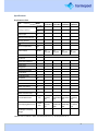
Specifications
Performance data
Unit Model
ZVWX4013
ZVWX4023
ZVWX4033
ZVWX4053
Heating Capacity*
kW
4,0
6,0
9,0
14,0
BTU/h
13600
20500
30700
47800
Power Input
kW
0,73
0,98
1,63
2,4
Maximum Pool Volume
m3
12
18
30
60
Running Current
A
2,9
4,5
7,5
12,0
COP
4,1
5,1
4,9
5,0
Min air temperature
DegC
12
12
12
12
Power Supply
V/Ph/Hz
220-
240/1/50
220-
240/1/50
220-
240/1/50
220-
240/1/50
Controller
Mechanical control
Condenser
Titanium heat exchanger
Compressor Quantity
1
1
1
1
Compressor
rotary
rotary
rotary
rotary
Refrigerant
R407C
R407C
R407C
R407C
Refrigerant quantity
Kg
0,5
0,8
1,0
1,3
Fan quantity
1
1
1
1
Fan Power Input
W
20
25
25
30
Fan Speed
RPM
950
900
900
890
Fan Direction
horizontal
horizontal
horizontal
horizontal
Noise at 2m
dB(A)
51
54
55
57
Water Connection
mm
50
50
50
50
Nominal Water Flow
m3/h
3 - 5
4 - 6
4 - 7
4 - 7
Water Pressure Drop
(max)
kPa
10
10
12
15
Unit Net Dimensions
L/W/H
mm
770/300/
490
936/360/5
50
936/360/5
50
1010/370/
615
Unit Shipping Dimensions
L/W/H
mm
825/315/
525
1090/390/
580
1090/390/
580
1170/415/
645
Net Weight / Shipping
Weight
Kg
32/36
40/46
50/54
60/67
*Measurement conditions: water inlet temperature 27 ℃/ air temperature 27 ℃

5
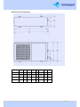
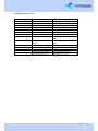
Dimensions of the heat pump
A
B
C
D
E
F
G
H
ZVWX4013
213
293
770
810
80
200
455
485
ZVWX4023
280
360
936
970
80
200
521
551
ZVWX4033
280
360
936
970
80
200
521
551
ZVWX4053
301
370
1010
1050
83
270
585
615

6
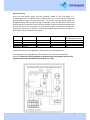
Installation
Installation items
The factory only provides the heat pump unit; the other items that are mentioned in the
illustration are to be provided by the user or installer.
Attention!
○ All feeding of chemicals to the pool water has to be done downstream of the heat
pump.
○ Install a bypass when the flow of the pool pump is more than 20% above the rated flow
of the heat exchanger of the heat pump.
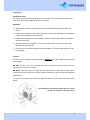
○ Install the heat pump on a solid foundation and use the damping rubbers to eliminate
vibrations and noise.
○ Always keep the unit straight up. If the unit has been tilted or put on his side, allow
24h before starting the unit.
○ The unit may be installed virtually anywhere outdoors. For indoor pools please consult
your supplier.
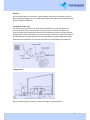
Location
The unit may be installed virtually anywhere
outdoors
. For indoor pools please consult
your supplier.
DO NOT
put the unit in an enclosed area with a limited air volume where the unit
discharge air will be re-circulated.
DO NOT
put the unit next to shrubs, which can block the air inlet. Such locations deny
a continuous source of fresh air, which reduces its efficiency and may prevent adequate
heat delivery.
The picture below give the minimum required distances from each side of the heat
pump.
Install the heat pump where you have the best access
to warm air during the swimming season

7
Distance
Install the heat pump as close to the swimming pool as possible to minimize the loss of
heat through the piping. Put it on a solid base and place the rubber blocks under the heat
pump to eliminate vibrations.
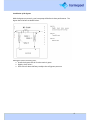
Installation of the valve
The placement of the chlorinator, water balance equipment, and the placement of
injectors of chemicals, are very important aspects of the installation. All addition of
chemicals have to be done downstream from the heat pump. Failure to protect the heat
pump unit from chemical damage is not covered by your warranty. A check-valve must be
installed between the heat pump and the chemical feeder to prevent back-siphoning of
chemically saturated water into the heat pump where it will damage the components.
Configuration
Note: the above piping connection is only an example for demonstration.

8
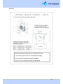
Installation of the bypass
With the bypass set correctly, your heat pump will deliver its best performance. The
bypass has to be built as shown below:
Setting the valves of the by-pass:
○
Install the bypass with all 3 valves entirely open
○
Slightly close valve 1
○
Close valve 3 about half way to adjust the refrigerant pressure

9
Electrical wiring
Verify the local power supply and the operating voltage of the heat pump. It is
recommended to use a separate circuit breaker (slow type – D curve) for the heat pump
together with the proper wiring characteristics. The current to the heat pump should only
be applied when the filter pump is running. For example, a relay controlled by the filter pump
could be used to activate the current to the heat pump. Connect the electrical supply to the
junction box inside the heat pump. All heat pumps require a single-phase connection.
Earthing the heat pump is required to protect you against electrical shocks caused by an
eventual short circuit inside the heat pump.
Values in this table are only guidelines. Please check your local regulations.
The heat pump is not equipped with a flow switch or any other kind of water flow
detection. Therefore, the heat pump has to be wired electrically together with the filter
pump to ensure water flow while the heat pump is running.
Model
Power supply (Volt)
Circuit breaker (A)
Running current (A)
Cable diameter (mm2)
for cable length max 15m
ZVWX4013
220-240
16
3,3
2,5
ZVWX4023
220-240
16
4,8
2,5
ZVWX4033
220-240
20
7,5
2,5
ZVWX4053
220-240
20
13
2,5

10
Start-up procedure
Start-up Procedure - after the installation is completed, you should follow these steps:
1. Set the by-pass valve 1 entirely open. Turn on your filter pump. Check for water
leaks and verify flow to and from the pool.
2. Turn on the electrical power supply to the unit and turn the unit ON with the
switch. Slightly close valve 1 until the heat pump starts.
3. After running a few minutes, check if the air leaving the side of the unit is cooler.
4. Allow the unit and pool pump to run 24 hours per day until desired pool water
temperature is reached. When the set temperature is reached, the unit just shuts
off. The unit will now automatically restart (as long as your pool pump is running)
when the pool temperature drops more than 1 degree Celsius below set
temperature. Several days are needed to bring the temperature of your swimming
pool water to its required value.
Time Delay - the unit is equipped with a 3-minute built-in delay to protect control circuit
components and to eliminate restart cycling and contactor chatter. This time delay will
automatically restart the unit approximately 3 minutes after each circuit interruption. Even
a brief power interruption will activate this delay and prevent the unit from starting until
the 3-minute countdown is completed.
Daily use of the heat pump
The heat pump can be switched on an off via the on-off switch. The heat pump can also be
connected to the same power grid as your filtration pump, so that the heat pump is
switched on automatically as soon as the filtration pump is switched on.
It must be avoided that the heat pump receives electrical current when the filtration pump
is not being used. In this case, the heat pump will start, overheat and stop working due to
the high temperature protection. In the long term, this can cause damage to the heat
pump, which will not be covered by your warranty.
Under 12 degC, a low temperature alarm will stop the heat pump functioning to prevent
freezing of the heat pump.
Condensation
Since the heat pump cools down the air about 8 - 12 °C, water may condense on the fins of
the evaporator. If the relative humidity is very high, this could be as much as several liters
an hour. Sometimes this condensation water is wrongly considered as swimming pool
water.

11
Guidelines
Water chemistry
Special care should be taken to keep the chemical balance of your swimming pool within
limits:
pH 7,0 – 7,8
Free chlorine 0,5 – 1,2 mg/l
TAC 80 – 150 mg/l (10°F – 30°F)
Salt max 8 g/l
Attention!
○ Failure to keep the swimming pool water between above limits will void the
warranty
○ When the concentration of one or more products mentioned above becomes too
high, irrevocable damage to your heat pump may occur. Make sure that you
always install water treatment equipment after the heat pump.
○ When an automatic chemical feeder is installed in the plumbing, it must be
installed downstream of the heat pump.
○ A check valve must be installed between the heat pump and the chemical feeder to
prevent back-siphoning of chemically saturated water into the heat pump where it
will damage the components.
Winter-ready
Attention! Failure to winterize could cause damage to the heat pump and will void
warranty
In areas where freezing temperatures occur, you should protect your pump, filter and heat
pump from the elements. Perform the following steps to completely drain the heat pump:
1. Turn off the electrical power to the heat pump at the main breaker panel.
2. Shut off the water supply to the heat pump: close valves 2 and 3 on the by-pass
completely.
3. Disconnect the water inlet and outlet and let the water drain from the heat pump.
4. Re-connect the water inlet and outlet loosely to prevent debris entering the
connections.

12
Spring start-up
If your heat pump has been winterized, perform the following steps when starting the
system in the spring:
1. Inspect the system for any debris or structural problems.
2. Connect the water inlet and outlet unions firmly.
3. Turn on the filter pump to supply water to the heat pump. Adjust the by-pass to
allow water flow through the heat pump.
4. Turn on the electrical power to the heat pump at the main breaker panel.
Owner inspection
The ECO heat pumps are designed and constructed to provide long performance life when
installed and operated properly under normal conditions. Periodic inspections are
important to keep your heat pump running safely and efficiently through the years. The
following basic guidelines are suggested for your inspection:
1. Make sure the front of the unit is accessible for future service.
2. Keep the surrounding areas of the heat pump clear of all debris.
3. Keep all plants and shrubs trimmed and away from the heat pump.
4. Keep lawn sprinkler heads from spraying on the heat pump to prevent corrosion
and damage. Use a deflector if needed.
5. If the unit is installed under a very sharp roof pitch or under a roof without a gutter,
a gutter or diverter should be fitted to prevent excessive water from pouring down
onto the unit.
6. Do not use the heat pump if any part has been under water. Immediately call a
qualified professional technician to inspect the heat pump and replace any part of
the control system, which has been submerged.
The heat pump will produce condensation (water) while in operation. The heat pump base
is designed to allow the condensation to exit through the bottom drain port. The
condensation will increase as the outdoor air humidity level increases. Check the following
at regular intervals to ensure proper condensate drainage:
1. Visually inspect and clear the bottom drain port of any debris that could clog the
port.
2. Keep the air intake area and discharge area clear of debris so the airflow through
the heat pump is not restricted. The cooler discharge air should not accumulate and
be drawn into the side air intake coils.
During normal operation, the heat pump produces ten to twenty liters of
condensate per hour. If condensate drainage is above this range during operation
or if water continues to drain from the base when the heat pump is not in
operation for more than an hour, a leak in the internal plumbing may have
occurred. Call a qualified heat pump technician to investigate the problem.
Attention! A quick way to verify that the water running through the drain is condensation
water is to shut off the unit and keep the pool pump running. If the water stops running
out of the base pan, it is condensation water.

13
Maintenance and inspection
Maintenance
o Check the water supply to the unit often. Low water flow and air entering into the
system should be avoided, as this will diminish the units’ performance and reliability.
You should clean the pool/spa filter regularly to avoid damage to the unit as a result of
the dirty or clogged filter.
o The area around the unit should be dry, clean and well ventilated. Clean the side
heating exchanger regularly to maintain good heat exchange and to save energy.
o Only a certified technician should service the operation pressure of the refrigerant
system.
o Check the power supply and cable connection often. Should the unit begin to operate
abnormally, switch it off and contact a qualified technician.
o In winter, please discharge all water from the water pump and other systems to
prevent damage from freezing.
o You should discharge the water at the bottom of the heat pump if the unit will not
work for an extended period of time. You should check the unit thoroughly and fill the
system with water fully before using it for the first time after a prolonged period of no
usage.
Warnings
○ Improper installation will create an electrical hazard, which could result in serious
injury.
○ DO NOT attempt any internal adjustments inside the heater.
○ Keep your hands and hair clear of the fan blades to avoid injury.
○ If you are not familiar with your pool filtering system and heater:
Do not attempt to adjust or service without consulting your dealer, professional
pool or air conditioning contractor.
Read the entire installation and users guide before attempting to use, service or
adjust the heater or pool filtering system.
Note: Turn off power to the unit prior to attempt service or repair.

14
Problems and solutions
Problem
Cause
Solution
Heat pump not
running
1. No electricity
1. Switch on the electrical power
2. Heat pump not turned on
2. Switch on the heat pump
3. Water pump not running
3. Switch on the water pump
4. Wrong temperature
setting
4. Adjust the temperature
setting
5. Bypass wrong adjusted
5. Adjust bypass as shown in
manual
6. No gas pressure
6. Call your technician
7. Time delayed operation
7. Wait 3 min for heat pump to
start
8. Air temperature below
12degC
10°C
8. Wait until temperature has
risen
No sufficient heating
1. Obstacles blocking air flow
1. Increase access of fresh air
2. Ice on the evaporator
2. Turn heat pump off (too cold
air)
3. By-pass wrong adjusted
3. Re-adjust the by-pass
4. Too much water flow
4. Adjust the by-pass

15
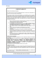
Checklist

16
Warranty
-
 1
1
-
 2
2
-
 3
3
-
 4
4
-
 5
5
-
 6
6
-
 7
7
-
 8
8
-
 9
9
-
 10
10
-
 11
11
-
 12
12
-
 13
13
-
 14
14
-
 15
15
-
 16
16


Harmopool ZVWX4013 Instructions Manual
- Category
- Heat pumps
- Type
- Instructions Manual
- This manual is also suitable for
Ask a question and I''ll find the answer in the document
Finding information in a document is now easier with AI
Other documents
-
Alto AS-H40Y User manual
-
 Guangdong Phnix Eco-Energy Solution PASRW015-U Installation Instructions Manual
-
Calorex PPT12 Installation guide
-
-
Dimplex LAS 10MT Operating instructions
-
-
 Filtermaster HP12.5A Installation Instructions Manual
-
Aquacal 121 Installation guide
-
 Hayward Pool HP50951T In Ground Pool/SPA Heat Pump Heaters User manual
-


