

INSTRUCTION
MANUAL
THIS
MODEL IS NOT A TOY
THESE
INSTRUCTIONS
SHOULD
BE
READ
BY A
SUPERVISING
ADULT
DRAGONFLITE
95 2.4GHz RTR
RACING
SAILBOAT
MODEL No; 8811
IMPORTANT:
- This is not a toy. Assembly and operating of this boat requires adult supervision.
- Please take time to read these instructions carefully and completely before attempting to operate your model. This manual contains the
instructions you need to safely build operate and maintain you R/C sailboat.
BOX
CONTENTS
t=lr->scjcDr-ig=nt=m

BASIC
BOAT
TERMINOLOGY
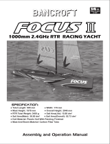
BOW The front of the boat,
STERN The back of the boat.
PORT
This is the left side of the boat when viewed from the Stern.
STARBOARD
This is the right side of the boat when viewed from the Stern.
HULL
The body of the boat.
DECK The upoer surface of the
Hull.
KEEL
A weignted biade that protrudes from the bottom of the hull as a means of providing lateral stability.
RUDDER
Tne n.nged verticai blade mounted at the Stern used as a steering device.
INSTRUCTION
MANUAL
3

DISPLAY
STAND
ASSEMBLY
1
Identify all stand components from box.
2
Bolt ttie plastic moulded components together with the twelve nut & bolts supplied.
3
Construct the leg sections. Note:
AJI
teg and
stretcher
tubes
are of
equal
length.
4 Fit the three stretcher tubes.
5
Fix the soft EVA foam supports to the top surface of the stand to protect the Hull from scratches.
KEEL
&
KEEL
BULB
ASSEMBLY
Identify all Keel & Bulb components from box.
Insert plastic 'Shoes' into bulb slot. f^a^ k*«»/ "f»^
5
»''
C^rtgi.
Tip: To
make it
easier
to align the bolt
holes
in the
Fixing
Disk, mark the
centres
of
the
threaded
holes
on the
side
o' '"e
^yg
Insert the Fixing Disk into the pre-drilled hole in the Keel taking care to align the threaded holes and screw in the
'"cN-'-eac
c;
ensure everything is aligned correctly It's a good idea at this point to stick the disk in place with a piece of thin face
"
ce.e
moving whilst fitting into the Keel Bulb. Then remove bolt,
ai'tiPC
S^O
Slide the Keel into the Bulb, between the Plastic Shoes and secure with the hex-head bolt.
Repeat step four for the top fixing.
Slide the top of the Keel into the Hull and secure with the remaining hex-head bolt.
use nf<LAKc4^
kc€,\A
kj}n<,n
I
INSTRUCTION
MANUAL

RUDDER
ASSEMBLY
1
Identify all Rudder components from box. 6rM»?
Vl^^ L £4-
>lH\oin
WAi^Ct- GtC»i^
*"
2
Insert Rudder into Hull.
3 Loosely fit the metal Rudder Arm on to the Steering Connector Rod and slide down over metal Rudder Shaft. Ensure the Rudder is
pushed fully up into the Hull then, pushing the Rudder Arm down, tighten the grub screw. This will locate on the flat section of the metal
Rudder Shaft.
4 Set the Ruoder Blade so that it's in perfect fore/aft alignment and tighten the top grub screw to locate the tiler arm onto the Steering
Connector Rod.
Note:
Rudder
alignment
v^il!
need
to be
checked
and adjusted when the boat is first powered up
with
the radio
gear
switched on.
MAINSAIL
RIGGING
:-e,
Be'ore
you start building the rig it's
important
that
you read the three points below, they apply to the whole of the rigging procedure.
To
aMid the Dyneema cord fraying when cut, put a few
drops
of
thin
CA glue
into
the cord at the position of the cut then cut through the
gtued
cord at an angle.
You
will
then have a hard, sharp point to the cut end
that
will
be
easy
to thread through the
Bowsies.
After
tying a knot and
trimming
off any
spare
cord, put a drop of
thin
CA glue on the knot to
secure
it.
Extra
time spent securing all knots
at this
stage
will
ensure
the long term
reliability
of the boat.
Thread
all
Bowsies
correctly as shown in the following diagram:-
_ 5
Tie
a
substantial
knot
in
me
end
of
the
cord,
trim
off
any
2
surplus
cord,
apply
a
drop
of
CA
glue
to
tfie
knot
and
pull
back
into
tfie
circular
recess
in
the
Bowsie.
, il
c
4.'i-rf,
TriM kn»i
ittttA.
RIGGING
PROCEDURE
If you follow all the dimensions stated in these rigging instructions, the boat will have a good, basic rig trim that will give it the sailing
characteristics and performance the designers intended.
1
Adjust the Sliding Deck Plate to align with the second graduation from the back as shown below,
INSTRUCTION
MANUAL
5

8
(9
FitthewireMainsailLuff Rings to all six eyelets down the Mainsail Luff (front edge),
vo r»» \^,*..^- Aon<^
Slide the Mast Stub into the base of the Mast, taking care that the bevelled edge of the plastic collar is facing downwards.
Slide the whole Main Boom assembly on to the Mast Stub from below.
Starting with the lower Mainsail Luff Ring, slide all rings down the Mast.
- K.
ftw^S
Push the
B^ksHy
C?^e ara'^asthead Plug assembly into the top of the Mast. Cut
a
250mm length
of
Dyneema and tie the head
of
the Mainsail to the Backstay Crane as shown. Align the top of the sail with the top of the metal mast reinforcement
ring.
Note: Tie this
with
oniy a
single
strand of
Dyneema,
this
will
allow the
head
of
the
sail
to
swivel
easily
when
the boat is running
with
the wind anp the
booms
are
sheeted
out at
8CP.
Vet »
^o^seneth.
bet
cr«.i»€
H
f
6f
6* S^-i^
Cut
a
300mm length
of
Dyneema and tie the Cunningham (downhaul) as shown. Start by tying one end to the eye in the top of the
Gooseneck fitting, take the cord through the eye at the bottom of the Mainsail Luff, back through the Gooseneck eye, lead
it
back along
the Boom, through
a
Bowsie and the eye in the Compression Strut fitting and finish off back through the Bowsie. JiO^ttit.
9 Hook the eye in the Mainsail Clew (bottom rear comer) onto the Mainsail Clew Hook.
10 Using
a
pair of thin nosed pliers close up slightly the open end of the Hook to prevent the sail eye slipping off the hook when sailing.
Note:
This
can be
opened
out again
with
a
flat
bladed
screwdriver
if you
need
to
remove
the sail.
11 Cut
a
900mm length
of
Dyneema for the Backstay Tie one end to the end hole in the Backstay Crane (see photo 7). Tie one of the
supplied 6mm metal rings to the bottom end (see photo 12). Slide the Mast and rigged Mainsail into the Mast Socket in the deck.
12 To make the adjustable lower section of the Backstay cut
a
500mm length
of
Dyneema, tie
a
loop in one end, thread the other end
through the first two holes in
a
Bowsie, then through the metal ring at the bottom of the Backstay and finish
of
back at the Bowsie. Hook
the loop into the metal hook in the Transom (back edge of the hull), apply
a
light tension to the Backstay, position the Bowsie roughly
midway along the lower cord and tie
it
off
13 Adjust the Compression Strut so that the Leech (back edge) of the Mainsail is under light tension and then back
it
off
a
turn to allow the
Leech to twist slightly. Adjust the Cunnigham to apply very light tension down the Luff of the
sail.
14 Set the length of the Backstay as shown in the diagram opposite.
15 Adjust position
of
Silicon Rings SR5
&
SR6 and the Mainsail Clew Hook so the Mainsail Foot can form
a
cutve with a distance of
approximately 25mm between the centre
of
the boom tube and the sail foot at its midpoint.
6
MANUAL

INSTRUCTION
MANUAL

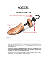
JIB
BOOM
SETUP
Counterweight
Jib
Boom
Front
End
Fitting
Ri
1
O
Ring
Jib
Clew
HOOK
Jib
Sheet
Guicie
1
Set the Jib Sheet Guide and Silicon Ring SR1 to the position shown above.
2
Cut
a
450mm fength
of
Dyneema to form the Jib Boom hook-down. Tie
a
loop
of
approximately 25mm length in one end and secure
the knot with a drop of CA
glue.
Make a mark at 65mm from the end of the Ji»ef.
Loop
3
Thread the Hook-Down line as shown in photo 3. Start by threading the loose end of the cord up through the lower, central eye in the
Boom Joiner, then through the top, central eye, back down through the lower eye again, lead It forwards along the underside of the
Boom,
through the first two holes in
a
Bowsie, through the rear of the two eyes in the Front End Fitting and take
it
back through the
final hole in the Bowsie, Do not tie off the final knot until completing the following stage. Adjust the cord so that the mark you made
is
positioned at the lower edge of the Boom Joiner and set the Bowsie midway between the front end fitting and the boom joiner and tie
off the final knot to secure the Bowsie. '—clffiCf
•fo
F^•*»>+
£"»i*t
f
J+fiA
j
Note:
When
the
full
rig is
completed
the
easiest
way to install the rig is as follows:
-
Insert
the
Mast
into
the
Mast
Socket
in the
Hull.
-
Slacken
off the
Bowsie
adjuster
on the Jib Hook-Down, thread the loop through the
front
Deck
Eye
(Deck
Eye 1),
lead
it
back
through
Deck
Eye
2 and
hook
the loop
over
the
Jib
Deck
Hook. Tighten the Hook-Down
Bowsie
to get the Jib
Boom
as low to the
deck
as
possible.
-
Hook
the
Backstay
on to the
Backstay
Hook
in the
Transom
and
tension
the
Backstay
Bowsie.
-
When
de-rigging do the
reverse
of this
process.
Using
this rigging
procedure
there is no
need
to adjust the
Forestay
tension
so the
correct
rig
trim
is quick and
easy
to
achieve.
d.
' •
B
4
s
,
— 9
B
4© F»-e»»+
*»»^
4«'Hi'»3
RIGGING
THE JIB
4 Cut
a
200mm length
of
Dyneema and tie one end to the frorit hole in the Backstay Crane. Tie one of the 6mm Metal Rings to the other
end
at a
distance of 15mm from Backstay Crane hole.
QcH^f
i< fkM tS
rt>m
.
lOmiti-limm
\* kt.Hcl-
5
Remove the Counteniveight from the front end of the Jib Boom, make sure
it
is screwed on tightiy to it's metal shaft and secure the
thread with
a
drop of thin CA glue.
Note:
At this
stage
make
sure
the Jib
Luff
is
free
to
slide
on it's wire
Forestay
If it is sticking at any point gently
free
it
off taking
care
not to
crease
the sail.
6
Push the Counterweight shaft through the loop in the bottom of the wire Forestay and bacK into the Front End Fitting leaving
approximately 5mm
of
shaft showing.
7 (Not
shown
-
see photo
9
on
page
6) Hook the eye in the Jib Cle bottom rpp
c^- e " o
the Jib Clew Hook.
8 (Not
shown
-
see photo 10 on
page
6) Using
a
pair
of
thin nosed pesccse '"e open end of the hook to prevent the eye
slipping off the hook when sailing. Note:
This
can be
opened
out aga ^
- - = c
aa<^o
-crewdriver
if
you
need
to
remove
the sail.
9 Cut
a
250mm length
of
Dyneema to form the Jib Cunningham fdov r-^a
- ^
'o-^t corner of fhe
sa/V),
Start by tying one end
to
the lower front hole in the Boom Joiner(a), take
it
fonwards through
f^c
_ =
ir a
Bowsie(b), then forward through the front eye
in the Front End Fltting(c), up through the sail eyelet(d) and back oc
" ~
eye(c) again and back through the final hole in the
Bow9ie(Q).
SQt thQ
BowciQ
in
a
cQntral
position and adjust
tfie
cord tc
r
«sac
of
5mm
between
tfie
Dottom
edge
ot tne
sail
and tne
top edge of the Front End Fitting and tie off the final knot to secure tne Bowsie.
8 cdh-*Sfcit=frig=Ht=:^
!s»s
:-.:£TPUCTION
MANUAL

10 Slacken off the Bowsie adjuster on the Jib Hook-Down, thread the loop through the front Deck Eye (Deck Eye 1), lead it back through
Deck Eye 2 and hook the loop over the Jib Deck Hook. Tighten the hook-down Bowsie to get the Jib Boom as low to the deck as possible.
11 Cut a 200mm length of Dyneema to form the top of the Forestay Tie one end to the wire loop in the top of the Forestay wire, thread up
through the first two holes of a Bowsie, through the metal ring and back through the final eye of the Bowsie. Pull some tension into the
Forestay and tie off the final knot in the Bowsie with the Bowsie positioned about 10mm from the metal
ring.
When secured, pull down
to apply more tension into the Forestay until the Luff of the Jib starts to wrinkle. Cut a 150mm length of Dyneema and tie the top eyelet
J
in the jib to the wire loop in the Forestay with enough tension to remove the wrinkles in the sail's Luff. —
Note:
Before
tying
tfie
sail
tiead
ensure
tlie
gap is
stilt
5mm
between
the Jib
Foot
and the top of the
Front
End
Fitting.
After
this is
complete,
the
Bowsie
on the Jib Cunningham can then be
used
to fine tune the
tension
in the Jib
Luff.
12 Now set the mast rake (angle) by adjusting the Forestay Bowsie to obtain the dimensions shown in the rig diagram on the next page.
To achieve these measurements you will have put a lot of tension into the Forestay and Backstay This tension is needed to keep the rig
stable which will give you consistent handling characteristics in different wind conditions.
13 Cut a 1000mm length of Dyneema to form the Topping Lift, Start by tying one end to the metal ring in the Forestay (See photo 11). Then
tie the bottom end of the cord to the ring attached to the Bowsie adjuster at the back end of the Jib Boom. Adjust the Bowsie to allow a
little slack in the Jib Leech (back edge).
14 Adjust position of Silicon Rings SR2/3 and the Jib Clew Hook so the Jib Foot can form a curve with a distance of approximately
25mm between the centre of the boom tube and the sail foot at its midpoint.
At this stage you have completed the rigging, the next sections will cover the fitting of 'Sheets' (control lines) to the Booms and setting the
rig up for best performance and boat
trim.
11
iiliiiiiiiilil^s
r
Ceoiij/tr.
ui'tna
m. Jut
Jib
Cunningham
Adjuster
NSTRUCTION
MANUAL
Wirt
\oof>
0-+
+tn5i-|>»i.
'J>€*'^«^ 5L,^e*.„o«
b^k boo. 6arftp<^
tfL<jLiM54
-Cor
M3rr^**k,
-ft^M-e^i
ctA.t\e. -io -fop o-C
AftU

Sub:;
OL\t
A«n^ flL i'larilmj ^(iff
ifoa
sei
^o«-+»
UeauSK. tftosi ASff**^*€j-
\i WAS
Sct^t mAji
'"/^Z
5tM^
-^orti-<ac ^(.ckvil., -A/ctJ.^
bend
a*
dloircdl k^cti
4 t»r,^^
"^Vt
c:Jr-'s»gc=ir-if=IH=i3
INSTRUCTION
MANUAL

POWERING
UP THE
BOAT
If you've bougfit the 'Ready To Race' version of the boat you will have the Joysway Transmitter and Receiver The transmitter (Tx) and
Receiver (Rx) will already be 'bound' and full operating instructions for this radio set are supplied.
If you are using your own Tx/Rx equipment we will assume you will be familiar with all it's functions and the following guide covers the setup
of the boat only
1
Connect up the Servo, Winch and Battery Switch cables up to the Receiver as follows:
-
Rudder Servo plugs into Channel 1 socket.
-
Sail Winch plugs into Channel 3 socket
-
On/Off Switch plugs into Battery socket (check your own Tx manual for this connection)
2
Install four, AA batteries into the Battery Holder and secure into the tray with the silicone band provided. Plug the batteries into the spare
lead from the On/Off Switch.
3
With both Tx control sticks in their central positions switch on the boats On/Off Switch by pushing the wire switch arm forwards in the
cockpit as indicated by the sticker.
Note:
At ttiis
stage
check
that
the control
sticks
on
your
Transmitter
operate
In the
correct
direction.
Looking
forward from the
back
of the
boat
when
the
rudder
control
stick
is
moved
to the
right,
the
Rudder
should
turn
to the
right.
When
the
Sail
Winch control
stick
is
moved
down,
the clip on the Winch
Line
should
move
to its furthest
back
position
(sheeted
in).
If
either
of
these
actions
is
reversed,
consult
your
manual for instructions on how to
reverse
the
stick
actions.
4 With the rudder control stick and fine adjuster on the Transmitter set in their central position, check to see if the Rudder Blade is centred
in line with the Keel when viewed directly from behind. If not, use the Allen Key to adjust the top grub screw on the Rudder Arm.
5
Now set the sheeted in a.nd out positions for the Winch Line. Diagram 5 shows the ideal positions for these sheeting points. Set the
sheeted in (close hauled' position first. Pull the satlwinch control stick on the Tx fully down with it's fine adjuster set in its central
position,
if
the end of the winch line clip is in a different position to that shown, unscrew the drum on top of the Sail Winch and rotate
until the clip position is correct and then re-tighten the drum. The ideal amount of winch line travel between fully sheeted in and out is
128mm.
This travel will give you the ideal sheeted out position for running with the wind with the booms out.
Note:
It's a
good
idea
to mark
these
two
positions
on the
deck
as a permanent
reference
points for
consistent
sheeting
adjustment. The
sheeting
points
shown
are not too critical hut what
k
imnnrtant
the
Fimnunt
nf travel jrietween the two points of
128mm^
On
better
quality
transmitters
you
will
be able to adjust the
sheeting
end points individually through its
software
menus.
KJSTRUCTION
MANUAL

SHEETING
SETUP
1
Adjust the bowsies on the mainsheet bridle to position the metal sheeting ring centrally in the position shown in photo 1.
It
is essential
for consistent sheeting angle on both port and starboard tacks (When looking forward from the back of the boat
if
the wind is coming
over the right hand side
if
the hull you are sailing on starboard tack).
2
For initial sheet setup of both the Jib and Mainsheet, pull the winchline in to its close-hauled (sheeted fully in) position and don't move
it
until both sheets are fully installed.
3
Cut a 600mm length
of
Dyneema for the Mainsheet. Tie a loop in one end and clip
it
in to the Winch Line Clip(a), run it forward and
through the metal ring on the Mainsheet Bridie(b), up through the Mainsheet Guide{c) on the Mainboom, back along the boom through
the 'O' Ring(d), through the first two holes in a Bowsie(e), back through the first hole in the Boom Joiner(f) and forward through the final
hole in the Bowsie(g). With the Mainboom positioned on the hull's centreline, position the bowsie approximately midway between (c) & (f)
and tie off the final knot to secure the Bowsie.
4 Cut an 850mm-length of Dyneema to form the Jibsheet. Tie a loop in one end and clip
it
in to the Winch Line Clip(a), run
it
forward
underneath the Mainsheet Bridle(b), forward through Deck Eye 3(c), up through Jibsheet Guide(d), run
it
forwards underneath the
Jib Boom, through the 'O'Ring(e), through the first two holes of a Bowsie(f), forward and through the rear hole in the Boom Joiner(g)
and back through the final hole in the Bowsie(h). Hold the back end of the Jib Boom over the edge of the Hull (Gunwhale), position the
Bowsie approximately midway between (d)
&
(g) and tie the final knot to secure the Bowsie.
5
With the Winchline still in its fully sheeted in position adjust the Bowsies on the Jibsheet and Mainsheet so the boom rear ends are
in the positions shown in Diagram 5 (opposite page). If you have the 128mm of winchline travel set up when you sheet out the booms
should be approximately in positions shown.
You should now almost have a fully set up rig. The only trimming left to do is to adjust the amount of twist in the leeches (back edges) of
both sails. The twist in the Mainsail can be controlled by adjusting the metal Compression Strut, the Jib twist is controlled by adjusting the
Bowsie at the bottom of the Topping Lift. It's hard to define the amount of twist in figures, but the photos on the opposite page show a well
adjusted rig with correct twist and boom sheeting angles. If you can match this rig setting you will have a well balanced and easy to sail boat.
6 Before you put the boat on the water fit the clear Deck Hatch and seal with one of the supplied adhesive Deck Patches. An easy
method to do this is to lay the adhesive Deck Patches face down on a smooth, hard surface, peel back the backing paper and place
the clear Deck Hatch upside down in the centre of the patch. Turn over and locate in the Deck Hatch Opening in the deck, make sure
the adhesive patch is pressed down to form a waterproof seal around the hatch. You are now ready to saill
cJr-*siCfczfr-if=lit=i_
Ub«f>,
X4«w
LabJi
art.
S'/i,)c
e%,
cut- \t»
K^I4
-tc
S'/^.i'f^^
^^^^^
12
INSTRUCTION
MANUAL

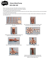
Sheeted Out: The Mainboom
- shouid sheet out to around 80°
to the Huli's centreline
Sheetea
Out
Sheeted In: The end of
the Jib Boom sfiould be
over the inner edge of the
Gunwhale,
Sheeted In: The end of the
(Mainboom should be over the
inner edge of ihe cockpit
INSTRUCTION
MANUAL

BASIC
SAILING
TERMINOLOGY
Unlike propeller driven boats that you basically point and accelerate, sailboats present an interesting challenge. Sailing requires constant
reaction to w/ater movements, any wind gusts and any wind direction changes. These reactions then require adjustment of the rudder and
sails in order to find the best possible course. There is no substitute for actual 'on-the-water' experience and after your first couple of outings
you may want to read through this manual again in order to help you to gain a better understanding of the 'art' of sailing. While learning to
sail,
it is a good idea to pick up on as much sailing terminology as possible. This will make it easier to grasp some aspects of the sport.
How
To
Sail Your Boat Wind
Beam
Reach
Sails:
Each
at a position of 45°
Rudder:
In center position
Broad
Reach
Sails:
Letting
both
out a
little
more
Rudder:
to the
left
starboard
Tack-Running
Sails:
Letting
both
out to
their maximum position
Rudder:
in center position
ulsd
«
Bearing
Away
Sails:
Let
both
out so as not to
flap
Rudder;
To the
left
Port
Tack
-
Close
Hauled
Sails:
Keeping pulled in
Rudder:
To be held at the center
as
long as the
sails
do not
flap
Port Tack-Running
Sails:
Letting
both
out to
their maximum position
Rudder:
in center
position
Broad
Reah
o.
Sails:
Pulling
both
in
a
little
Rudder:
In center position
Luffing Up
Sails:
Pulling in bit by bit
Rudder:
To the
left
Tacking
Sails:
Keeping pulled in
Rudder:
To the
right
Tacking
Sails:
Keeping pulled in
Rudder:
To the
left
<
45
Starboard
Tack
-
Close
Hauled
Sails:
Keeping pulled in
Rudder:
To be held at the center
as
long as the
sails
do no!
flap
\g
/
Sails: Keep poited
in
Rudder; To the left
/ /
Port
Tack
-
Close
Hauled
Sails;
Keep
pulling in
Rudder:
To be held at the center
as
long as the
sails
do not
shiver
START
Broad
Reach
Sails:
Each
at a position of 45°
Rudder:
In center position
Luffing Up
Sails;
Pulling
both
in all the way
Rudder;
To the
left
IMPORTANT
NOTICE
-
Only sail your DragonFlite 95 in still bodies of water Never sail
it
in running water such as rivers or tidal waters. If you loose control of
the boat you could loose it foreverl
-
Never attempt to swim after a stalled or stuck boat. Wait patiently for the bioat to drift ashore or be rescued.
14
INSTRUCTION
MANUAL

MAINTENANCE
SPARE
PARTS
LIST
If properly rigged and maintained the DragonFlite 95 will
be a very 'dry' boat. This is a very good thing as water and
electrics are not the best of friends!
There are some essential steps you need to take to keep
your boat working as it should, these are:
-
The bearings in the top and bottom of the Gooseneck
sr'Ot,
a be washed In clean, fresh water after every
c^t -g ' yoj sail in saltwater
-
2' / joncate the bearings with bearing lube or
a~, 5-^ 3'C'oduct.
"cle boat and rig with clean, fresh water
Duting if you sail in salhvater
Zzi^"
>"e Hatch Cover and allow the '"side of the boat
•:
cc-^pletely dry out after sailing. Do not store the boat
,'.
either water or condensation inside the hull, it will
=ead to electrical failure through ccrosjon or 'black wire'
-a'^re.
Dyteerr.a
cord can shrink in ceftsrn conditions. So
c"ec'- :te" r-at ai' .c-r' 3 set: 'cs 'emain correct.
"3-c sa'2 s:c'e -re Sa-s .•.:- c'ea: care. Don't leave
•'-e-'
- a"-z c: 5:5 '.s zi its stand, lay
c:?." zz.:- z" 5 =r" s.-£:e .'.tne rig downwind
"5
,','5-
- -55 -esc '^e ngs in a rigid rig
cr<
;"5'..
i'-'zziz
5~a-your
rigs - they are
5te
SPARE
PARTS
LIST
item No iterr Nar^e
5S-101 DF95
Cor-.c
e:; - = ; .. .-,':
581102 DF95 Comt; s--r S = :
i-:;^-;
.
aa-103 DF95Complete ;
=:-;ir-r
561104 DF95 Complete Z -z-m-c
i.c' 105 DF95
"A"
50 micron ,"ny a.' i ^ si s
£51106 DF95
"B"
75 micron myiar f r- sa s
SS' 107 DF95
"C"
75 micron mylar film sa .s
•
-08 DF95 "D" 75 micron mylar
film
saPS
55-109 DF95 f(/tast Pack A
3s-no DF95 Mast Pack B
SS1111
0F95lv1astPackC
88^
-
•
J DF95 Mast Pack D
65
-
•' 3 DF05
».(ast
Head Pack A
:=33 .Vast Head Pack B
£?•
• • f 0=95 ysK -«ad Pack (C & D identical)
8811-8 D=35 Ma-Soc^ Faok C
881119 DF95uib3cDni?£ckA
881120
DF95 Jib Boc,-^-=ack
C-
881121
DF95 Jib Boom Pack C
881122
DF95 fulainsail
luff
Ring
{PK10)
881123 DF95 Transparent Hatcti(PK2)
881124
DF95 Water
seal
tape(PK2)
881125 DF95 Deck cloth patch(PK4)
881126
DF95 Front bumper{PK2)
881127
DF95 Sheeting pulley block(PK2)
881128
DF95 Fin box and mast
fitting
881129
DFSSRjdder
ml
1 ccrd -No
Sails)
-
cc-3 \ 3ail3\
•
zz'Z %c 3a,.s;
Item No
881130
881131
881132
881133
881134
881135
881136
881137
881138
881139
881140
881141
881142
881143
881144
881145
881146
881147
881148
881149
881150
881151
881152
881153
881154
881155
881157
881158
881159
881160
881161
881162
SS-163
531203
Item Name
DF95 Carbon keel
with
bolts
DF95 Bolts(PK4)for keel
DF95 Ballast
with
plastic Shoe
fitting
DF95
Plastic
shoe
DF95 Pushrod
DF95 Switch connector+Switch rod
DF95 Painted
Huil(without
decafs)+front bumper
DF95 Jib Boom Front End Fitting(PK4)
DF95 Boom Joiner (PK4)
DF95
Main
Boom Pack 0
DF95 Hull decais set
A
sails
reinforcement adhesive patches+battens
B
sails
reinforcement adhesive patches+battens
C
sails
reinforcement adhesive patches+battens
D
sails
reinforcement adhesive patches+l3attens
Stainless
steel wire for A jib
sail
(PK2)
stainless
steel wire for B jib
sail
(PK2)
Stainless
steel wire for C
Jib
sail
(PK2)
Stainless
steel wire for D jib
sail
(PK2)
Eyelet
(PK20) for reinforcement adhesive patch
Jib
luff
tape {2cm x 100cm) (PK10)
l3ouble-sided seam tape {50m) for Jib
luff
tape
280mm
short carbon keel
with
bolts
DF95 Mast
fitting
tube
DF95 Mainsheet Bridle Keelboat Fitting {Pk 2)
J4C05
transmitter{M0DE2)with J5G01R Receiver
DF95 Bearing {PK4)
DF95 Jib Boom Pack B
DF95 Painted Black
Hull(without
decals)+front bumper
DF95 Painted Blue Hull{without decals)+front bumper
DF95 Painted Purple Hull{without decals)+front tximper
DF95 Painted Orange Hull{vwthout decals)+front bumper
DF95 Painted Yellow Hull{without decals)+front bumper
Metal
sail
clew hook{PK10)
0.6mm
Dyneema cord(10m length)
Jib
txjom
counterweight
with
shaft(PK4)
Bo-.vsiefPKIO)
Suicon
tube+"0"ring{PK4)
S^e?:
"5 e-:aslic(2m)
-
a'icy rudder arm set
-
:
Ir-.:-a.
with
screws
-
«ni.c-T at
i~t~t^
••%«rr heut^ K€el
>
—i:
-.r-jfc,i
ir«.'«..T
msx^i
cJr-'Si£jCDr-if=iHz:t3
s
INSTRUCTION
MANUAL

-
 1
1
-
 2
2
-
 3
3
-
 4
4
-
 5
5
-
 6
6
-
 7
7
-
 8
8
-
 9
9
-
 10
10
-
 11
11
-
 12
12
-
 13
13
-
 14
14
-
 15
15
-
 16
16


Joysway 8811 User manual
- Type
- User manual
- This manual is also suitable for
Ask a question and I''ll find the answer in the document
Finding information in a document is now easier with AI
Related papers


Other documents
-
Deagostini Cutty Sark User guide
-
 DRAGONFLITE 95 8811 User manual
-
 Bancroft Focus II 1000mm 2.4GHz RTR Racing Yacht User manual
-
GRAUPNER Micro Magic RTR Rigging Instructions
-
 Out There LASER User manual
-
 Ultra-tow Hydraulic Pickup Truck Crane Owner's manual
-
 Woodlore 60021 Two Way Shoe Stretcher Operating instructions
-
Udi R/C UDI002 Operating instructions
-
 BLOTZ B15-OW-102 Assembly Instructions
-
Laser SB3 Rigging Manual


